1
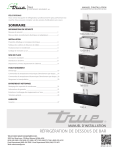
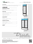
MIRA COMBIFLOW
SHOWER CONTROL
Installation & User Guide
These instructions are to be left with the user
1
the nation’s favourite for
PLUMBING & HEATING SUPPLIES
FREE SHIPPING
SECURE PAYMENTS
on all orders over £100 to mainland UK
shop online with confidence
FINANCE AVAILABLE
PRICE MATCH
spread the cost with low interest rates
always get the best deals available
we have
H U G E
R E D U C T I O N S
ON THOUSANDS OF ITEMS
Boilers
Bathroom suites
Radiators
Kitchen sinks & taps
Heating controls
Showers
Pipes & ittings
Wet rooms
Cylinders
Towel warmers
Fires
Bathroom furniture
Renewable energy
& much more
visit our website
plumbnation.co.uk
CALL US ON
0844
800
3460
CONTENTS
Introduction ............................................................................................. 3
Important Safety Information ................................................................. 4
Pack Contents Checklist ......................................................................... 5
Dimensions ............................................................................................. 7
Specifications .......................................................................................... 8
Pressure Range ................................................................................... 8
Temperatures ....................................................................................... 8
Connections ......................................................................................... 8
Standards and Approvals ..................................................................... 8
Installation Requirements ...................................................................... 9
Installation ............................................................................................. 14
Combiflow .......................................................................................... 14
1. Rear Inlet Supplies (rising or falling concealed pipework) ............... 14
2. Exposed Inlet Supplies (rising or falling surface pipework) ............. 17
Combiflow B ...................................................................................... 22
3. Solid and dry-lined walls................................................................. 22
4. Stud Partitions and Shower Enclosures (Front Face) ..................... 29
5. Laminated Panels and Shower Enclosures (Rear Face) ................. 30
Reversed Inlet Connections .................................................................. 32
Commissioning and Control Assembly Installation ........................... 34
Flow Regulator Installation and Filter Access ..................................... 34
Shroud Fitting and Removal ............................................................... 35
Maximum Temperature Setting .......................................................... 36
Adjusting Maximum Temperature Stop .............................................. 38
Temperature Override Button - Disable .............................................. 39
Lever Control Installation ................................................................... 40
Operation ............................................................................................... 41
Fault Diagnosis ..................................................................................... 42
Maintenance .......................................................................................... 45
Spare Parts ............................................................................................ 46
Accessories ........................................................................................... 50
Customer Service .................................................................... Back Page
2
INTRODUCTION
Thank you for purchasing a quality Mira product. To enjoy the full potential of your
new product, please take time to read this guide thoroughly, having done so, keep it
handy for future reference.
The Mira Combiflow is a pressure balanced shower valve with lever control which
maintains a constant outlet temperature irrespective of changes of inlet pressures
as long as the inlet water temperatures remain the same. It is not a thermostatic
shower control and does not sense supply temperature variations. Therefore, inlet
water temperatures especially the hot, should remain relatively constant.
The Mira Combiflow can be installed with the following packages:
Fully modulating multipoint gas water heaters.
Fully modulating combination boilers.
Unvented mains pressure systems.
Mains pressurised, instantaneous hot water heated from thermal store
systems.
Pumped systems.
Showering temperature and flow are adjusted by the shower lever control. The flow
rate is also determined by the supply pressures available at the inlets and internal
flow regulator if used (Note! The 8 l/min flow regulator supplied fitted is recommended
for use with fully modulating combination boilers and instantaneous water heaters).
Shower controls covered by this guide:
Mira Combiflow
Surface mounted pressure balanced shower control for connection to exposed
pipework, for high pressure applications (1.0 – 5.0 bar).
Mira Combiflow B
Built-in shower control for connection to concealed pipework, for high pressure
applications (1.0 – 5.0 bar).
If you experience any difficulty with the installation or operation of your new shower
control, then please refer to "Fault Diagnosis", before contacting Kohler Mira Limited.
Our telephone and fax numbers can be found on the back cover of this guide.
3
IMPORTANT SAFETY INFORMATION
Warning!
1. Products manufactured by us are safe and without risk provided they are installed,
used and maintained in good working order in accordance with our instructions
and recommendations.
2. When this shower is used with a fully modulating instantaneous multipoint water
heater or combination boiler the flow must be sufficient to keep the boiler ignited.
Therefore, it is important to ensure that the flow lever is positioned to the fully
open position. Adjusting the flow lever to reduce the water flow while
showering may result in an increase in temperature.
Caution!
1. Read all of these instructions.
2. Retain this guide for later use.
3. Pass on this guide in the event of change of ownership of the installation site.
4. Follow all warnings, cautions and instructions contained in this guide.
5. Anyone who may have difficulty understanding or operating the controls of any
shower should be attended whilst showering. Particular consideration should be
given to the young, the elderly, the infirm, or anyone inexperienced in the correct
operation of the controls.
6. The temperature control can be turned from FULL HOT to FULL COLD. As
such, turning the control to full hot will deliver water at the hot water storage
temperature.
7. When this product has reached the end of its serviceable life, it should be disposed
of in a safe manner, in accordance with current local authority recycling, or waste
disposal policy.
4
PACK CONTENTS CHECKLIST
X Tick the appropriate boxes to familiarize yourself with the part names and to
̊
confirm that the parts are included.
1. Mira Combiflow Surface Mounted Shower Control
1 x Shower Control
̊
1 x Cover Shroud
̊
1 x Lever Handle
2 x Pipe Concealing Plates
̊
1 x Handle Plug
̊
̊
1 x Override Lock and
Temperature Stop
1 x Quad Key
̊
̊
1 x Button Override
2 x 31/4" Fixing Screws
̊
2 x Wall plugs
5
̊
Disabler
̊
1 x 2.5 mm A/F
Hexagon Wrench
̊
2. Mira Combiflow B Shower Control
1 x Shower Control with Building-in Cover
1 x Concealing Plate
̊
1 x Foam Seal
̊
̊
1 x Mounting Plate Assembly
1 x Lever Handle
Handle Plug
2 x Bracket
̊
̊
2 x M4 x 8 mm Screws
̊
2 x No. 8 x 11/2" Fixing Screws
̊
2 x Wall plugs
Quad Key
̊
̊
3. Documentation
1 x Installation and User Guide
1 x Guarantee Registration Form
1 x Installation Template
̊
2 x M4 x 30 mm Screws
̊
2 x M5 x 25mm Screws
̊
1 x 2.5 mm A/F
Hexagon Wrench
̊
̊
̊
6
̊
̊
DIMENSIONS
1. Mira Combiflow
153
71
131
30
35
147
209
NOTE:- NOT TO SCALE - All dimensions are nominal and in millimetres
2. Mira Combiflow B
137
149
95
47 - 70
155
74
38
208
7
166
SPECIFICATIONS
Mira Combiflow and Mira Combiflow B
Pressure Range
Minimum maintained pressure: 1.0 bar
Maximum maintained pressure: 5.0 bar
Maximum static pressure: 10 bar.
Note! For optimum performance, the initial supply pressures should be nominally
equal.
Temperatures
Hot and cold water supply temperatures MUST remain relatively constant.
Maximum hot water temperature: 80°C.
Ideally the hot water temperature should never exceed 65°C. A water temperature of
60°C is considered sufficient to meet all normal requirements and will minimize the
deposition of scale in hard water areas.
Connections
Inlet
15 mm Compression (Combiflow B).
15 mm Compression (Combiflow).
Outlet
1
/2'' BSP male (Combiflow).
15 mm Compression (Combiflow B).
Standards and Approvals
1.
Designed to be used within systems in line with BS6700.
2.
BS 6700 recommends that the temperature of stored water should never exceed
65 °C. A stored water temperature of 60 °C is considered sufficient to meet all
normal requirements and will minimise the deposition of scale in hard water areas.
8
INSTALLATION REQUIREMENTS
Read the section 'Important Safety Information' first.
Installation must be carried out in accordance with these instructions, and must be
conducted by designated, qualified and competent personnel.
1. Installations must comply with UK Water Regulations/ Bye-laws (Scotland), and
Building and Plumbing Regulations in force at the time of installation.
2. Layout and sizing of pipework must be such that when other services are used,
pressures at the shower mixer control inlets do not fall below the recommended
minimum (1 bar). The pressure balancing performance is impaired below 1 bar.
When fitted with some heater appliances the minimum maintained pressure may
need to be above 1 bar, to keep the flow rate sufficiently high in order to ensure
the gas flame stays lit.
3. The Mira Combiflow is not suitable for installation as part of a gravity-fed plumbing
system (i.e. in conjunction with a hot water cylinder and cold water storage cistern),
unless used in conjunction with an inlet pump producing a maintained pressure
of at least 1 bar.
4. When used with a fully modulating multipoint or combination boiler above 5 bar
maintained pressure, a pressure reducing valve will be necessary. For
information on measuring system pressures refer to section: 'Installation
Requirements, Measuring System Pressures'. For further information on
pressure reducing valves consult your local plumbing stockist.
5. Supply pipes MUST be flushed to clear debris before connecting the shower
control.
6. Conveniently situated isolating valves are recommended to be fitted for servicing
purposes.
7. If the shower control is to be used with a fully modulating multipoint water heater,
fully modulating combination boiler, thermal store or unvented system an
expansion vessel must be fitted to accommodate the expansion of water in the
domestic hot water supply (this may already be part of the system, check the
details on the boiler/heater or contact the boiler/heater manufacturer).
8. No form of outlet flow control should be fitted, only Mira recommended fittings
should be used in the outlet pipework.
9. Do not install the product in a position in which service access is restricted.
10. Do not fit any form of flow control in the shower outlet.
11. Do not use excessive force when making connections.
12. Do not install the product in a position where it could become frozen.
9
Key to symbols appearing throughout this guide
Float operated valve
Twin impeller inlet pump
Stop or servicing valve
Tempering valve
Shower control
Mini expansion vessel
Warning or overflow pipe
Non-return Valve
Drop tight pressure reducing
valve (PRV)
Typical Suitable Installations
1.
Instantaneous multipoint water heaters and combination boilers
The shower MUST be installed with a multipoint gas water heater or combination
boiler of a fully modulating design (i.e. where the water draw-off rate indirectly
controls the gas flow rate to the burner).
An expansion vessel MUST be fitted (and regularly maintained) if any form of
backflow prevention device is fitted, e.g. non-return valve, PRV. This will ensure
that excess expansion or pulse pressures do not damage the product or the
plumbing system. The expansion vessel may already be fitted within the boiler
(check with the manufacturer) and is in addition to the normally larger central
heating expansion vessel.
COLD HOT
10
2.
Unvented mains pressure showers
The shower can be installed with an unvented, stored hot water cylinder. Only a
"competent person" as defined by the Building Regulations may fit this type of
system.
For packages with no cold water take off after the appliance reducing valve, it
will be necessary to fit an additional drop tight pressure reducing valve when the
mains pressure is over 5 bar. The drop tight pressure reducing valve must be set
at the same value as the unvented package pressure reducing valve.
Note! An expansion vessel MUST be fitted (and regularly maintained) if any
form of backflow prevention device is fitted, e.g. non-return valve, PRV. This will
ensure that excess expansion or pulse pressures do not damage the product or
the plumbing system.
Safety devices not shown for
clarity
COLD
Expansion Vessel
HOT
Reduced pressure to cold inlet of shower
Reduced pressure to cold inlet of shower
High Inlet Pressure
High Inlet Pressure
Reduced pressure
to unvented cylinder
Combined outlet PRV
with internal non-return valves
- Expansion vessel required.
Reduced pressure
to unvented cylinder
Cold takeoff after PRV
- Expansion pressure taken up by
unvented cylinder expansion vessel.
11
3.
Mains pressurised instantaneous hot water shower, heated from a thermal
store.
Packages of this type, fitted with a tempering valve can be used.
A drop tight pressure reducing valve MUST be fitted if the supply pressures
exceed 5 bar maintained.
An expansion vessel MUST be fitted (and regularly maintained) if any form of
backflow prevention device is fitted, e.g. non-return valve, PRV. This will ensure
that excess expansion or pulse pressures do not damage the product or the
plumbing system. The expansion vessel may already be fitted externally or
internally within the thermal store (check with thermal store manufacturer).
COLD HOT
4.
Pumped showers (inlet pumps)
The shower can be installed with an inlet pump (twin impeller). The pump MUST
be located on the floor next to the hot water cylinder. The hot water cylinder/vent
pipes must be arranged as shown to achieve air separation.
90°
30° to 60°
Air Separation
12
Measuring System Pressures
1.
2.
3.
4.
General
It is important that the system pressures are within the range specified for the
Mira Combiflow (refer to section: 'Specifications').
If the system pressure is not known then the system pressure MUST be measured
as explained in this section.
Pressures are those present at the inlet to the appliance either whilst running
(maintained) or in the off state (static). Nearby hot and cold taps connected to
the same proposed feed pipes as the appliance can be used to measure the
static pressure. No other fitting or appliance should be in use at this time.
Water pressures vary throughout the day, therefore you must ensure that water
pressures do not drop below or exceed the minimum/maximum required (refer to
section: 'Specifications').
To measure static pressure (Refer to illustration below)
With the pressure testing device firmly connected to a tap drawing from one of
the proposed feed pipes and the outlet from the device in the off position, the tap
is turned on and the static pressure noted.
To measure maintained pressure (Refer to illustration below)
The pressure testing device is connected as above, the taps turned on and the
outlet from the device opened until a flow of around 5 l/min is obtained (this is
easily done by timing the flow into a calibrated container). The maintained pressure
which can be expected when the shower is in operation can then be read. This
should be carried out on the hot and cold supply.
To measure pressure drop
Pressure drop results from another fitting being turned on when the shower is in
use. Having checked the maintained pressure as in 3. and with the device still
discharging at approximately 5 l/min, turn on a second draw-off from the same
feed pipe. This new reading will show the pressure drop from 3. and should be
above the minimum maintained pressure recommended by the manufacturer.
Pressure
Gauge
Ball Valve
Hose Type Tap
Connector
Pressure Testing Device
13
INSTALLATION
Combiflow
1. Rear Inlet Supplies (rising or falling concealed pipework)
Read the section 'Installation Requirements' first.
1.1 Decide on a suitable position for the
shower control. The position of the
shower control and the shower fittings
must provide a minimum gap of 25
mm between the spill-over level of the
shower tray/bath and the handset. This
is to prevent backsiphonage.
Hose Retaining Ring
25 mm Minimum
Spill-over
Level
1.2 Use the installation template to mark
the positions of two holes diagonally
for mounting the shower mixer and the
pipe centres.
Installation Template
Spirit Level
1.3 For solid walls drill two holes diagonally
with a 6 mm diameter drill and insert
the wall plugs (supplied). For other
types of wall structure alternative wall
plugs may be required.
Drill 2 Holes Diagonally
Alternative Position
14
1.4 Use a spirit level and pencil to mark
the route of the hot and cold water
supply pipes at 153 mm centres.
Note! The Combiflow is supplied with
inlet connections hot left, cold right
and bottom outlet as standard. For
installations with reversed hot and
cold supplies a reversed
temperature lever will be required.
Available from Kohler Mira
Customer Services. It is therefore
recommended that the correct pipe
orientation is achieved.
1.5 Remove the plaster and brick/block to
the required depth to conceal the
pipework.
Note! Depth must be sufficient to
prevent pipe concealing plates fouling
on the plumbing elbows.
mm
53
1
es
ntr
Ce
18 mm from
finished wall
surface
1.6 Install the supply pipes. The pipes
must project 18 mm from the finished
surface of the wall at 153 mm centres.
Use the installation template to make
sure that the pipes are in the right
position.
32 mm
Circular
Recess
Elbow
1.7 Finish the surface of the wall as
required. The recesses from which the
pipes
emerge
must
also
accommodate the 32 mm diameter x
10 mm deep flanges on the pipe
concealing plates.
10 mm minimum
between elbow and
finished wall surface.
1.8 Fit the pipe concealing plates over the
hot and cold supply pipes.
Concealing Plates
15
1.9 Thoroughly flush the hot and cold
water supply pipes. The supplies
must be clean and free from debris
before connecting the shower
control. Failure to do so may result
in product malfunction.
1.10 Slide the compression nuts and olives
over the supply pipes.
Olive
Compression
Nut
1.11 Locate the Combiflow shower control
on to the pipes and hold it in position.
Note! Make sure that the screws &
wall plugs supplied with the product
are used for mounting the shower.
1.12 Use a suitable screwdriver to tighten
the two screws through the body. The
screws will hold the shower control in
position.
1.13 Use a suitable spanner to
tighten the compression nuts
(anticlockwise rotation when viewed
from front). Protect the chrome plated
surfaces with a cloth.
1.14 Refer to Commissioning for details on
the flow regulator installation.
1.15 Turn on the water supplies and check
for any leaks.
1.16 Refer to Commissioning and Control
Assembly Fitting Instructions.
Shower Fittings
1.17 Install the shower fittings. Refer to the
Installation and User Guide for the
shower fittings.
16
Screw
2. Exposed Inlet Supplies (rising or falling surface pipework)
Read the section 'Installation Requirements' first.
Hose Retaining Ring
Rising Supplies
2.1 Decide on a suitable position for the
shower control. The position of the
shower control and the shower fittings
must provide a minimum gap of
25 mm between the spill-over level of
the shower tray/bath and the handset.
This is to prevent backsiphonage.
25 mm Minimum
Spill-over Level
Spirit Level
2.2 Use the installation template to mark
the positions of two holes diagonally
for mounting the shower mixer and the
pipe centres.
2.3 For solid walls drill two holes diagonally
with a 6 mm diameter drill and insert
the wall plugs (supplied). For other
types of wall structure alternative wall
plugs may be required.
Installation Template
Drill 2 Holes Diagonally
Alternative Position
17
2.4 Use the quad key or a suitable
screwdriver to remove the blanking
plugs.
Inlet Nipples
2.5 Use the quad key to remove the inlet
nipples from the rear of the mixer
valve.
2.6 Screw the inlet nipples, complete with Quad
'O' seals, into the blanking plug holes
flat face end first.Tighten the inlet
nipples with the quad key.
Key
Blanking Plugs
Blanking Plugs
2.7 Fit the blanking plugs complete with
'O' seals, into the rear inlet nipple
holes.Tighten the blanking plugs.
2.8 Locate the Combiflow shower control
on to the wall.
Note! Make sure that the screws
supplied with the product are used for
mounting the shower.
'O' Seal
Inlet Nipples
2.9 Use a suitable screwdriver to tighten
the two screws through the body. The
screws will hold the shower control in
position.
18
Quad Key
2.10 Install the hot and cold supply pipes
35 mm from the finished wall at
153 mm centres.
Use the installation template to make
sure that the pipes are in the right
position.
Note! The Combiflow is supplied with
inlet connections hot left, cold right
and bottom outlet as standard. For
installations with reversed hot and
cold supplies a reversed
temperature lever will be required.
Available from Kohler Mira
Customer Services. It is therefore
recommended that the correct pipe
orientation is achieved.
2.11 Thoroughly flush the hot and cold
water supply pipes. The supplies
must be clean and free from debris
before connecting the shower
control. Failure to do so may result
in product malfunction.
2.12 Slide the compression nuts and olives
over the supply pipes.
2.13 Insert the hot and cold supply pipes
fully into the inlet nipples and slide the
olives and compression nuts into
place.
2.14 Use a suitable spanner to tighten the
compression nuts. Protect the chrome
plated surfaces with a cloth.
2.15 Refer to section: 'Commissioning
and Control Assembly Installation,
Flow Regulator Installation and
Filter Access' for details on the flow
regulator installation.
2.16 Turn on the water supplies and check
for any leaks.
2.17 Refer to section: 'Commissioning
and Control Assembly Installation'.
19
Olive
Compression Nut
Installation Template
Falling Supplies
2.18 Follow the installation instructions 2.1
to 2.7.
Outlet Cap
Outlet Blanking Plug
2.19 Use the quad key to remove the outlet
nipple.
2.20 Carefully lever the outlet cap from the
outlet blanking plug in the shower
control body.
2.21 Use the quad key to remove the outlet
blanking plug.
2.22 Fit the outlet nipple, complete with 'O'
seal into the hole previously blanked.
Tighten the outlet nipple with the quad
key.
Outlet Nipple
2.23 Fit the outlet blanking plug, complete
with 'O' seal, into the outlet hole
between the two inlet nipples. Tighten
the outlet blanking plug with the quad
key.
2.24 Fit the outlet cap correctly. The
matching contours of the outlet cap
and shower control body must be
aligned.
2.25 Locate the Combiflow shower control
on to the wall.
20
Flat Face
2.26 Use a suitable screwdriver to tighten
the two screws through the body. The
screws will hold the shower control in
position.
2.27 Install the hot and cold supply pipes
35 mm from the finished wall at
153 mm centres.
Use the installation template to make
sure the pipes are in the right position.
2.28 Refer to section: 'Reversed Inlet
Connections' and follow instructions
8.2. to 8.10. This will put the cartridge
assembly, the indicator trim and the
temperature knob in the correct
orientation for hot left and cold right
inlet supplies.
2.29 Follow the installation instructions
2.12. to 2.15. inclusive.
2.30 Refer to Commissioning for details on
the flow regulator installation.
Compression Nut
Installation
Template
2.31 Turn on the water supplies and check
for any leaks.
2.32 Refer to section: 'Commissioning
and Control Assembly Installation'.
Shower Fittings.
2.33 Install the shower fittings. Refer to the
Installation and User Guide for the
shower fittings.
21
Olive
Combiflow B
3. Solid and dry-lined walls
Read the section “Installation Requirements” first.
The built-in shower control is supplied with support brackets that can be used to
install the shower control into a solid or dry-lined wall structure.
3.1 Decide on a suitable position for the
shower control. The position of the
shower control and the shower fittings
must provide a minimum gap of
25 mm between the spill-over level of
the shower tray/bath and the handset.
This is to prevent backsiphonage.
Hose Retaining
Ring
25 mm Minimum
Spill-over Level
3.2 Determine the route for the incoming
hot and cold supply pipework.
3.3 Determine the route for the outlet
pipework. For further information on the
installation of the shower fittings refer
to the Installation and User Guide.
Note! The Combiflow B is supplied with
inlet connections hot left, cold right
and top outlet as standard. For
installations with reversed hot and cold
refer to section: 'Reversed Inlet
Connections'.
For installations with reversed hot
and cold supplies a reversed
temperature lever will be required.
Available from Kohler Mira
Customer Services. It is therefore
recommended that the correct pipe
orientation is achieved.
22
Outlet Pipe for BIR
BIV Outlet
BIV Outlet
Hot Inlet
Cold Inlet
Shower Control
3.4 Remove the building in shroud.
Note! If the Combiflow B is to be fitted
with top inlets then the bottom inlet
compression fittings must be swapped
using the quad key with the top inlet
blanking plugs. Make sure all seals are
fitted and components are tightened.
Refer to section: 'Exposed Inlet
Supplies (rising or falling surface
pipework)' and follow instructions 2.4
to 2.5.
3.6 If installing the shower into a solid wall,
mark an opening sufficient to
accommodate the shower control
approximately 245 mm x 145 mm on
the surface of the wall.
Screw
Bracket
Bracket
48 mm
48 mm
245 mm
23
145 mm
3.5 Fit the two brackets (supplied) to the
mixer using the 2 x M4 x 8 mm screws
(supplied).
Note! These can be fitted diagonally
as required to enable easy fitting and
access of the inlet connection.
Building in Shroud
3.7 Mark the route of the inlet and outlet
pipes.
3.8 Remove the plaster and brick/block for
the shower control to a depth between
47 and 70 mm from the finished
surface of the wall, with a finished wall
surface thickness between 6 and
23 mm.
6 mm Minimum Depth
Finished Wall
Surface
Alternative
support
fixing
3.9 Remove the plaster and brick/block for
the inlet and outlet pipes.
3.10 Mark the support bracket fixing hole
positions.
Note! Support brackets can be
adjusted to find a secure fixing and
ensure easier spanner access to
compression connections. The
support bracket should be
positioned so that the valve can be
fitted level and the compression
fittings can be easily tightened.
Support
Bracket
Finished Wall
Surface
23 mm
Maximum Depth
47 mm
Support Bracket
Adjustment
3.11 Drill a 6 mm diameter hole at each of
the marked positions and insert the wall
plugs (supplied).
Note! For stud partition installations
alternative fixings may be required.
Alternatively the support brackets can
be removed and the two mounting
holes in the body can be used to fit to
the wall cavity or to a timber nogging.
24
Fixing Holes
To make sure that the shroud fully
locates over the body of the
Combiflow B, the tabs on the buildingin shroud MUST be bent inwards where
the shroud meets the mounting
brackets (refer to illustration).
Note! If using the fixing holes on the
body casting to fix to the back wall or
wooden noggin, the mounting brackets
are not required and therefore you do
not need to bend back the tabs.
Failure to carry out this procedure will
result in the ‘min’ to ‘max’ building in
depth shown on the shroud being
incorrect.
3.12 Temporarily fit the building-in shroud.
Check that the valve is level. Align the
holes in the support bracket with the
holes in the wall and secure the unit
with the two fixing screws (supplied).
Remove the building-in shroud to allow
access to pipe connections.
Support Bracket
Adjustment
Alternative Rear
Fixing
Fixing Screw
25
3.13 Align the hot and cold supply and
outlet pipes with the valve but do not
connect to the valve.
3.14 The supplies must be clean and free
from debris before connecting the
shower control. Failure to do so
may result in product malfunction.
Note! The Combiflow is supplied with
inlet connections hot left, cold right
and top outlet as standard. For
installations with reversed hot and cold
refer to section: 'Reversed inlet
connections'.
For installations with reversed hot
and cold supplies a reversed
temperature lever will be required.
Available from Kohler Mira
Customer Services. It is therefore
recommended that the correct pipe
orientation is achieved.
3.15 Insert the hot and cold supply and
outlet pipes through the compression
nuts and olives. Make sure that each
pipe is pushed fully into the valve.
Note! For BIV outlet with falling inlet
supplies the inlet pipes may have to
be set deeper into the wall.
3.16 Hold each pipe in position and use a
suitable spanner to tighten the
compression nuts.
26
Compression
Nut
Note! Before turning on the water
supplies
refer
to
section:
'Commissioning and Control
Assembly Installation'.
Tiling Area
3.15 Turn on the water supplies and check
for any leaks.
3.16 Refit the building-in shroud removed
earlier. Secure the shroud in position
with the screws.
3.17 Plaster and tile as necessary up to the
sides of the building-in shroud. Make
sure that the finished tiled wall surface
is within the area as shown on the
building in shroud.
3.18 When the plaster/tiles have set,
remove the screws and pull the entire
building-in shroud away.
Retain the screws for later use.
27
Alternative
Rear Fixing
3.19 Remove the backplate from the
concealing plate and fit in position with
the screws provided.
Back Plate
Note! For shallow building in depths
and front face panel mounting use the
two short M5 x 25 mm screws
(provided) in line with the inlet pipework.
Do not overtighten the screws as
this may distort the valve position
within the wall.
Note! If the finish is particularly uneven
(i.e. due to grout lines), apply a small
amount of silicone sealant to ensure a
seal.
Alternative
Short Screws
Foam Seal
3.20 Slide the foam seal over the chrome
shroud and align onto the back plate.
3.21 Fit the concealing plate over the
shroud. Firmly push the concealing
plate until it clips into position onto the
backplate.
3.22 Carefully slide the concealing plate into
position over the shroud. Firmly push
until it clips to the backplate.
3.23 Fit the control lever assembly refer to
section: 'Commissioning and
Control Assembly Installation'
Shower Fittings
3.24 Install the shower fittings. Refer to the
shower fittings Installation and User
Guide.
28
Concealing
Plate
4. Stud Partitions and Shower Enclosures (Front Face)
Read the section “Installation Requirements” first.
The built-in shower control is supplied with support brackets that can be used to
install the shower control into the front face of a stud partition wall structure or shower
enclosures. The front face installation of the support bracket is only practical where
an applied surface finish e.g. plaster or tiles can conceal the brackets.
Spirit Level
4.1 Refer to section: 'Installation, 3. Solid
and dry-lined walls' and follow
instructions 3.1. to 3.3.
4.2 Use the installation template (supplied)
to mark the size of the hole required in
the partition/enclosure. Bend the tabs
inwards and use a spirit level to make
sure that the hole is marked
symmetrically. Mark around the
outside edge of the template.
Installation
Template
Bend tabs outwards and
place the spirit level on
tabs to level the template
Mark around the
template with a pencil
4.3 Carefully cut the hole in the panel.
Note! The valve requires a clearance
depth of 47 mm, with a panel/wall
thickness of up to 17 mm. The area
shown on the building-in shroud can
be used as a depth gauge. Panel/wall
thicknesses in excess of 17 mm can
be accommodated, but clearance may
be required around the outlet and inlet
connections to allow insertion of the
pipe and tightening of the compression
nut.
4.4 To complete the installation, refer to
section: 'Installation, 3. Solid and
dry-lined walls' and follow instructions
3.8 to 3.23.
6 mm Minimum Depth of Finish
17 mm Maximum
Finished
Wall Surface
47 mm Clearance
Depth
Alternative
Support
Fixing
Finished
Wall Surface
Pipe
23 mm Maximum
Finish Depth
Support Bracket
29
5. Laminated Panels and Shower Enclosures (Rear Face)
Read the section 'Installation Requirements' first.
The built-in shower control is supplied with support brackets that can be used to
install the shower control onto the rear face of a laminated panel or preformed shower
cubicle.
Spirit Level
Installation
Template
Note! This installation is possible with
a finished wall thickness of between
4 and 21 mm.
5.1 Refer to section: 'Installation, 3. Solid
and dry-lined walls' and follow
instructions 3.1. to 3.3.
5.2 Use the installation template (supplied)
to mark the size of the hole required
on the panel.
Bend tabs inwards and
place the spirit level on
tabs to level the template
Mark through the
slots in the template
with a pencil
4 mm Minimum Depth
Bend the tabs inwards and use a spirit
level to make sure that the hole is
marked symmetrically.
47 mm Clearance Depth
Mark through the inner slots of the
template.
5.3 Carefully cut the hole in the panel.
Note! The valve requires a clearance
depth of 47 mm, with a finished wall
thickness of between 4 and 21 mm
Alternative
Support
Fixing
5.4 Drill a 5 mm diameter hole at each of
the marked positions.
21 mm
Maximum Depth
30
5.6 Remove the building-in shroud and fix
the support brackets and valve in
position using the two M4 x 30 mm
screws (supplied).
Alternative Rear Fixing
5.7 Align the hot and cold supply and outlet
pipes with the valve but do not secure
the pipes.
5.8 To complete the installation, refer to
section: 'Installation, 3. Solid and
dry-lined walls' and follow instructions
3.11 to 3.23.
Note! For stud partition installations
alternative fixing may be required.
Alternatively the support brackets can
be removed and the two alternative
rear mounting holes in the body can
be used to fit to the wall cavity or to a
timber nogging.
31
M4 x 30 mm Screws
REVERSED INLET CONNECTIONS
The Combiflow exposed is supplied with back inlet connections hot left, cold right
and bottom outlet.
Flow Regulator
Hot
Cold
The Combiflow B is supplied with bottom inlet connections hot left, cold right and
top outlet.
Outlet
Flow Regulator
Hot
Cold
1.1 If the hot and cold inlet connections have been reversed during installation and
cannot be corrected then a reversed lever with the red and blue indicators fitted
in reverse will be required to indicate correct operation. (Available from Kohler
Mira Customer Service).
Important! The flow regulator must always be installed in the hot side of the
valve. Therefore if the hot and cold inlet connections have been reversed make
sure that the flow regulator is fitted in the filter housing on the hot side of the
valve. Refer to section: 'Commissioning and Control Assembly Installation'
for the flow regulator installation instructions.
Exposed
Built in
Flow Regulator
Cold
Hot
Cold
Reversed Lever required
Flow Regulator
Hot
Reversed Lever required
32
The shower control should be installed with hot on the left and cold on the right. If the
inlet positions are changed, i.e. top inlets are used then the internal cartridge must be
turned through 180° to enable the lever control to operate correctly.
The following procedure must be performed:
1.2 If the water supply has been connected and turned on, isolate the supplies and
operate the control lever to relieve the pressure.
1.3 Carefully pull off the control lever and shroud assembly. (refer to section:
'Commissioning and Control Assembly Installation').
1.4 Remove the four cartridge retaining screws (refer to section: 'Maintenance').
1.5 Remove the upper body / flow cartridge assembly (refer to section: 'Maintenance').
1.6 Lever the pressure balancing cartridge from the body and rotate the cartridge
180° and replace.
Caution! Take care not to damage the two inlet seals during assembly (refer
to section: 'Maintenance').
1.7 Refit the upper cartridge body and make sure that the two ports are aligned with
the two ports on the pressure balancing cartridge.
1.8 Refit the four cartridge retaining screws.
Caution! The upper cartridge must be fully pushed onto the pressure balancing
cartridge before securing with the retaining screws. If the upper cartridge seal is
visible then the cartridges are not aligned correctly.
1.9 Restore the hot and cold supplies and check for leaks.
1.10 Refit the shroud and the control lever assembly (refer to section: 'Commissioning
and Control Assembly Installation').
If the seal is visible then the cartridges
are not aligned and fully engaged
33
COMMISSIONING AND CONTROL ASSEMBLY INSTALLATION
Flow Regulator Installation and Filter Access
For most combination boiler and instantaneous water heater installations an 8 l/min
flow regulator (supplied fitted) is required in the hot supply of the shower mixer control.
This is to ensure a regular flow and thus a stable temperature.
Note! For other high pressure systems removal of the 8 l/min flow regulator (supplied
fitted) is recommended.
The flow regulator is fitted into the inlet filter housing as illustrated below.
Note! Make sure the flow regulator is fitted in the correct orientation either for the
Combiflow exposed or built-in (refer to illustrations below).
To access filters or the flow regulator once the shower has been installed, remove the
cover shroud (Combiflow exposed) or the concealing plate (Combiflow Built In).
Make sure that the 8 l/min white flow regulator is fitted for combination boiler and
instantaneous water heater systems.
Remove the flow regulator for high pressure and pumped systems.
Exposed
Built-in
Filter Housing
Hot Inlet
Hot Inlet
Inlet Strainer Filter
Inlet Strainer Filter
Flow Regulator
Flow regulator
34
Filter Housing
Shroud Fitting and Removal
Combiflow Exposed
Fit the shroud assembly.
1. Make sure that the override button assembly is aligned at the 1 O' clock position.
2. Engage the shroud into the body recess and push the shroud firmly onto the
body.
Note! Make sure that the override button is firmly in position inside the shroud
and the grey button guide is positioned corrrectly on the body. Failure to fit the
shroud correctly may cause the control lever to rub on the shroud..
For removal hold the shroud firmly and pull away from the valve.
Body Recess
Override Button at the
1 O' Clock Position
Button Guide
Combiflow Built in
The shroud assembly is supplied fitted, if it is removed then follow this procedure.
1. Make sure that the override button assembly is aligned at the 1 O' clock position.
2. Make sure that the five raised locators within the shroud assembly fit into the
five slots of the brass upper body and push the shroud firmly onto the body.
Note! Make sure that the override button is firmly in position inside the shroud
and the white button guide is positioned corrrectly on the body. Failure to fit the
shroud correctly may cause the control lever to rub on the shroud.
For removal hold the shroud firmly and pull away from the valve.
Button Guide
Slots
35
Override Button at the
1 O' Clock Position
Maximum Temperature Setting
Read all the sections: Maximum temperature setting, Adjusting Maximum
Temperature Stop and Temperature Override Button Disable before carrying out
any of these procedures.
The following instructions are valid for both, Combiflow Exposed and Combiflow Built
in.
1.1 The Combiflow maximum temperature stop assembly is set to nominally 41 °C
at the factory (Note! This may vary according to the on-site water
temperatures).This equates to the two missing teeth of the white geared
maximum temperature stop ring being fitted in line with the raised part of the
plastic moulding on the red lever stop (as shown in the illustration). If the shower
has reversed inlets then approximately 41 °C equates to the two missing teeth
being fitted in line with the large locator on the red lever stop ring (as shown in the
illustration).
White M•maximum
Temperature Stop
Red Lever Stop
Maximum Temperature
Stop Assembly
This End of Raised
Part of Moulding
Missing Teeth
Red Lever Stop
Large Locator
Missing Teeth
Standard Inlet
Reversed Inlet
Rear View of Maximum temperature Stop Assembly
36
1.2 For standard inlets turn the square lever locator fully anticlockwise and clockwise
for reversed inlet.
Fit the maximum temperature stop assembly into the two slots either side of the
square lever locator on the shower control (Note! Make sure that the maximum
temperature stop assembly has the red side facing towards you. One slot is
wider than the other to make sure of correct installation, see illustration below).
Push the maximum temperature stop fully on.
Square Lever Locator
Red Upstands
Wider Slot
Front View standard inlet
1.3 Fit control lever onto square lever locator (see fitting control lever).
Lift lever towards you to turn the shower on to give a typical shower force.
Turn lever clockwise to increase temperature until movement stops and allow
temperature to stabilise. If this maximum temperature is satisfactory, then firmly
tighten grub screw and fit grub screw cover. If the temperature is not satisfactory
refer to 9.4.
(Note! For reversed inlets a reversed inlet control lever is required.
Anticlockwise movement will increase temperature. If the maximum
temperature is not satisfactory then the maximum temperature stop will
require adjustment.
37
Adjusting Maximum Temperature Stop
1.4 To adjust the maximum temperature position remove the lever.
Remove the red maximum stop ring by pulling on two red upstands
(Use pliers if necessary)
Standard Inlets
Pull the white maximum temperature stop apart from the red maximum lever
stop (Use pliers if necessary). Turn the white gear 1 or 2 gear teeth clockwise to
increase the maximum shower temperature or anticlockwise to decrease.
(Note! One gear tooth movement will increase or decrease the temperature by
approximately 2 °C) push together firmly.
Fit the red maximum temperature stop as described in 9.2.
Missing Teeth
-°C
+°C
Rear View of MaximumTemperature Stop Assembly
Reversed Inlets
Pull the white maximum temperature stop apart from the red maximum lever
stop (Use pliers if necessary). Turn the white gear 1 or 2 gear teeth anticlockwise
to increase the maximum shower temperature or clockwise to decrease.
(Note! One gear tooth movement will increase or decrease the temperature by
approximately 2 °C) push together firmly.
Fit the red maximum temperature stop as described in 9.2.
+°C
-°C
Missing Teeth
Rear View of MaximumTemperature Stop Assembly
38
Temperature Override Button - Disable
The Combiflow incorporates a temperature override button that allows the user to
override the preset maximum temperature. The following procedure can be used to
disable the override button, limiting the maximum temperature available to the preset
value. This setting is recommended for the young, the elderly, the infirm, or anyone
inexperienced in the correct operation of the controls.
1.5 Carefully remove the control lever.
1.6 Slot the white disabler button component into the red lever stop ring and push
fully in.
Note the two positions (See illustration).
Note this is already in the stored position in the Combiflow B.
1.7 Refit the control lever.
1.8 Reversing the above procedure will enable the override button.
In this position the Override
button WIILL NOT operate
In this Stored position Override
button WILL operate
Button Override
39
Lever Control Installation
Fit control lever
Push the control lever over the square lever locator and make sure that the lever is
pointing down.
Tighten the grub screw with the extra long 2.5 mm hexagonal key (supplied) and fit
the grey handle plug.
Note! It is easier to locate the hexagonal key into the grub screw before fitting the
lever.
Fit the lever plug after all of the maximum temperature commissioning has been
carried out.
Combiflow Exposed
Square Lever
Locator
Plug
Hexagonal Key
Combiflow Built in
Square Lever
Locator
Plug
Hexagonal Key
40
OPERATION
1. Combiflow and Combiflow B
The Combiflow incorporates a temperature override button that allows the user to
override the preset maximum temperature.
1.1 Pull the control lever to turn on the
water. Push the control lever to turn
off the water.
Note! When the Combiflow is installed
with a fully modulating multipoint or
combination type gas water heater, the
maintained mains water pressure, and
hence the flow, must be sufficient to
keep the heater ignited. Therefore, it
is important to make sure that the flow
knob is used in the fully open position
to help prevent variation in the hot
water supply temperature.
Warning! The Mira Combiflow is not
a thermostatic mixer valve,
reducing the flow by operating the
control lever during showering may
increase the temperature.
1.2 Turn the lever clockwise for warmer
water or anti clockwise for cooler water.
Caution! Operation will be in reverse
if the reversed lever is being used. The
preset maximum temperature can be
adjusted as required to suit both site
conditions and the user's comfort.
Refer to section: 'Commisioning and
Control Assembly Installation,
Maximum Temperature Setting'.
Warning! Operation of the override
button will allow a shower temperature
above the preset maximum.
1.3 To override the preset maximum
temperature depress the override
button and turn the temperature knob
further clockwise while keeping the
button depressed.
41
Temperature Lever
Override Button
FAULT DIAGNOSIS
The trouble shooting information tabled below gives details on what you can do as a
user should you encounter difficulties whilst operating the shower.
Note! Should these remedies prove to be unsuccessful in solving your problem, contact
your installer for further advice.
Key for applicability column
A - Instantaneous gas heated showers.
B - Unvented mains pressure showers/gravity pumped showers.
C - Mains pressurised, instantaneous hot water, heated from thermal store showers.
Malfunction
Shower
insufficiently hot.
Cause
Remedy
A B C
(a) Maximum
temperature
incorrectly set.
Reset adjustable
maximum
temperature.
X X X
(b) Heater not set on
maximum hot.
Consult heater
X
instructions or contact a
CORGI registered
installer.
Fit the flow regulator into X X X
hot inlet (Refer to flow
regulator installation)
(c) Flow rate still too
high.
Wide temperature (a) Insufficient flow rate
fluctuations from
causing the heater
shower when no
to cycle on and off.
other draw-off is
being made.
(b) Insufficient water
pressure causing
the heater to cycle
on and off.
(c) Heater not fully
modulating.
(d) See also 'Shower
insufficiently hot'.
Check and clean inlet
strainers. Make sure the
flow control is fully on.
X
Contact your local water
supplier or a CORGI
registered installer.
X
Contact a CORGI
registered installer.
X
Shower pattern
(a) The heater cannot
collapses when
supply several
another hot tap is
outlets at the same
turned on.
time.
(b) Inlet strainer
blocked.
Reduce the
simultaneous demand.
X
X
Check and clean inlet
strainers
X
X
42
X
Malfunction
Shower pattern
collapses when
another cold tap
is turned on.
Cause
Remedy
A B C
Contact the local water
(a) Property water
X X X
supply pipe partially supplier or your installer.
blocked or
undersized.
(b) Property stop or
Open valve.
X X X
servicing valve not
fully open.
Contact the local water
(c) Insufficient mains
X X X
cold water pressure. supplier or your installer.
(d) Inlet strainer
blocked.
Check and clean inlet
strainers.
X X X
Shower gives hot (a) Hot and cold water Refer to section:
supplies have been 'Installation, Reversed
water when turned
connected in
Inlet Supplies'.
cold and cold
reverse.
water when turned
hot.
X X X
Shower
insufficiently hot
without pressing
red button and
rotating further.
(a) Adjustable
maximum
temperature
incorrectly set.
Refer to section:
'Commissioning and
Control Assembly
Installation, Maximum
Temperature Setting'.
X X X
Shower force too
strong.
(a) Flow control fully
open.
Reduce the flow. Refer
to section: 'Operation'.
X
(b) Pressure above 5
bar.
(c) Flow regulator not
fitted.
(a) Heater appliance
not igniting due to
insufficient mains
pressure or flow.
(b) Heater appliance
not igniting due to
appliance fault.
(c) Product hot or cold
isolating valve not
fully open.
(d) Hot water run out.
(e) Inlet strainer
blocked.
Contact installer to fit a X X X
pressure reducing valve.
Fit flow regulator.
X
X
No hot water
available.
43
X
Contact the local water
supplier or a CORGI
registered installer.
X
Contact a CORGI
registered installer.
X
Open valve.
X X X
Wait until reheated.
Check and clean inlet
strainers.
X X
X X X
Malfunction
Shower starts
warm and then
runs cool.
Shower control
cannot be shut
off.
No flow or low
flow from shower
head.
Cause
Remedy
A B C
X
(a) Insufficient flow
rate.
Refer to 'Wide
temperature
fluctuations'.
(b) Hot water supply
temperature
dropped.
Wait for hot water to
reheat.
X X
Renew the cartridge.
Refer to section:
'Maintenance,
Cartridge Renewal'.
(b) ‘O’ seals damaged. Renew ‘O’ seals with
Service Pack.
X X X
(a) Supply stop valve
turned down or off.
Open valve.
X X X
(b) Inlet Strainers
blocked.
Clean or renew the inlet
strainers.
X X X
(c) Hose or handset
blocked.
Clear the blockage. If
necessary renew the
hose or handset.
X X X
(d) Spray plate
blocked.
Remove and clean.
X X X
(a) Ceramic flow
cartridge damaged.
44
X X X
MAINTENANCE
The Mira Combiflow is designed to be maintenance free, as such there are no
serviceable parts within the flow or pressure balancing cartridge. However regular
cleaning will keep the shower in pristine condition, refer to '1. Cleaning'. Strainers are
fitted to the inlets of the mixer to protect the cartridge and should give many years of
trouble free showering. Filters should be checked at yearly intervals and cleaned or
replaced to maintain optimum shower performance. Refer to section: 'Commissioning
and Control Assembly Installation, Flow Regulator Installation' for details on the
inlet filter location.
1. Cleaning
Many household cleaners contain abrasive and chemical substances, and should not
be used for cleaning plated or plastic fittings. These finishes should be cleaned with
a mild washing up detergent or soap solution, and then wiped dry using a soft cloth.
2. Ceramic Flow Cartridge Renewal
2.1 Refer to section: 'Reversed Inlet Connections' and follow instructions 1.3 to
1.4.
2.2 Unscrew and remove the headnut and remove the ceramic flow cartridge. Replace
with the new cartridge and make sure it is fitted in the correct orientation. Refit
the headnut.
2.3 Refer to section: 'Reversed Inlet Connections', instructions 1.10 to 1.11 and
section: 'Commissioning and Control Assembly Installation' to complete the
installation of the new ceramic flow cartridge.
Carefully Lever Out
3. Pressure Balancing Cartridge Renewal
3.1 Refer to section: 'Reversed Inlet Connections' and follow instruction 1.3 to 1.6.
Note! Before removing the pressure balancing cartridge note its position, to ensure
the correct orientation of the replacement.
3.2 Lever the pressure balancing cartridge from the shower body. Fit the new pressure
balancing cartridge and make sure it is fitted in the correct orientation.
3.3 Refer to section: 'Reversed Inlet Connections' and follow instructions 1.8 to
1.10 and section: 'Commissioning and Control Assembly Installation' to
complete installation of the new pressure balancing cartridge.
45
SPARE PARTS
Combiflow Exposed Spare Parts List
459.01
459.02
459.03
459.05
459.06
459.07
459.08
459.09
459.10
459.11
459.12
459.13
459.14
459.15
459.16
459.20
Lever Handle
Lever Handle (Reversed)
Cover Shroud Assembly
Flow Cartridge Assembly
Flow Cartridge Body
Pressure Balancing Cartridge
Filter, Flow Regulator and Plug Pack
Inlet Connector Assembly
Outlet Nipple
Outlet Blanking Plug
Filter and Flow Regulator Pack
Screw Pack (Not Illustrated)
Seal Pack (Not Illustrated)
Component Pack (Not Illustrated)
Installation Template
Inlet Blanking Plug
46
Combiflow Exposed Spare Parts Diagram
459.11
459.03
459.09
459.07
459.20
459.01
459.02
459.10
459.08
459.12
459.06
459.05
459.16
47
Combiflow Built in Spare Parts List
459.01
459.02
459.04
459.05
459.06
459.07
459.12
459.14
459.18
459.19
459.20
459.21
459.22
459.23
459.24
459.25
459.26
459.27
459.28
Lever Handle
Lever Handle (Reversed)
Cover Shroud Retaining Clip
Flow Cartridge Assembly
Flow Cartridge Body
Pressure Balancing Cartridge
Filter and Flow Regulator Pack
Seal Pack (Not Illustrated)
Cover Shroud Assembly
Concealing Plate Assembly
Inlet Blanking Plug
Outlet Connector Assembly
Screw Pack (Not Illustrated)
Wall Mounting Bracket
Component Pack (Not Illustrated)
Building-in Shroud
Installation Template
Inlet Connector Assembly
Filter, Flow Regulator and Plug Pack
48
Combiflow Built in Spare Parts Diagram
459.21
459.27
459.27
459.07
459.06
459.26
459.04
459.20
459.12
459.28
459.25
459.23
459.19
459.18
459.05
459.23
459.01
459.02
49
ACCESSORIES
DCV-H: An outlet double check valve, requiring a minimum inlet supply pressure
of 0.5 bar, which has been designed to prevent the backflow or backsiphonage of
potentially contaminated water, through shower controls which are fitted with a
flexible hose as part of the outlet shower fitting.
Available as an optional accessory from your Mira stockist.
DCV-H Outlet double check valve
50
NOTES
51
CUSTOMER SERVICE
Guarantee of Quality
Spare Parts
Mira Showers guarantee your product against any defect in
materials or workmanship for the period shown in the
Guarantee Registration Document included with your shower.
Alternatively, to confirm the applicable guarantee period
please contact Customer Services.
To validate the guarantee, please return your completed
registration card.
Within the guarantee period we will resolve defects, free of
charge, by repairing or replacing parts or modules as we
may choose.
To be free of charge, service work must only be undertaken
by Mira Showers or our approved agents in Northern Ireland
and Republic of Ireland.
Service under this guarantee does not affect the expiry
date. The guarantee on any exchanged parts or product
ends when the normal product guarantee period expires.
Not covered by this guarantee:
Damage or defects arising from incorrect installation,
improper use or lack of maintenance, including build-up of
limescale.
Damage or defects if the product is taken apart, repaired or
modified by any person not authorised by Mira Showers or
our approved agents.
This guarantee is in addition to your statutory and other
legal rights.
We maintain an extensive stock of spares, and aim to have
functional parts available for ten years from the date of final
manufacture of the product.
Spares can be purchased from approved stockists or
merchants (locations on request) or direct from Customer
Services.
Spares direct will normally be despatched within two working
days. Payment can be made by Visa or Mastercard at the
time of ordering. Should payment by cheque be preferred a
pro-forma invoice will be sent.
Note! In the interests of safety, spares requiring exposure
to mains voltages can only be sent to competent persons.
Before using your shower
Please take the time to read and understand the operating
and safety instructions detailed in this manual.
What to do if something goes wrong
If when you first use your shower it doesn’t function correctly,
first contact your installer to check that installation and
commissioning are satisfactory and in accordance with the
instructions in this manual. We are on-hand to offer you or
your installer any advice you may need.
Should this not resolve the difficulty, simply contact our
Customer Services who will give every assistance, and if
necessary arrange for our service engineer to visit.
If later the performance of your shower declines, consult
this manual to see whether simple home maintenance is
required. Please call our Customer Services to talk the
difficulty through, request service under guarantee if
applicable, or take advantage of our comprehensive
After-Sales service.
As part of our quality and training programme calls may be
recorded or monitored.
Our Customer Services Team is comprehensively trained
to provide every assistance you may need: help and advice,
spare parts or a service visit.
Service
Our Service Force is available to provide a quality service
at a reasonable cost. You will have the assurance of a Mira
trained engineer/agent, genuine Mira spares, and a 12 month
guarantee on the repair.
Payment should be made directly to the Service
Engineer/Agent, using Visa, Mastercard or a cheque
supported by a banker’s card.
To contact us
England, Scotland & Wales
Mira Showers Customer Services
Telephone: 0870 241 0888
8:30 am to 5:00 pm Working days (4:30 pm Friday)
8:30 am to 12.30 pm Saturday
E-mail:
[email protected]
Fax:
01242 282595
By Post:
Cromwell Road
Cheltenham
Gloucestershire
GL52 5EP
Northern Ireland
Wm H Leech & Son Ltd
Telephone: 028 9044 9257 – Mon to Fri 9 am-5pm
Fax:
028 9044 9234 – 24 hours
Post:
Maryland Industrial Estate
Ballygowan Road
Moneyreagh, Co Down
BT23 6BL
Republic of Ireland
Modern Plant Ltd
Telephone: 01 4591344 – Mon to Fri 9am to 5pm
Fax:
Dublin 01 4592329 – 24 hours
Post:
Otter House
Naas Road
Clondalkin
Dublin 22
Mira Showers
Mira is a registered trade mark of
Kohler Mira Limited.
Kohler Mira Ltd
The company reserves the right to alter
Cromwell Road,
product specifications without notice.
Cheltenham GL52 5EP.
www.mirashowers.com
P4479/2
52
UKAS
QUALITY
MANAGEMENT
003
FM 14648
© Kohler Mira Limited, July 2005