1
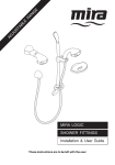
SHOWER FITTINGS Installation & User Guide THESE INSTRUCTIONS ARE TO BE LEFT WITH THE USER 1 Contents Section 1 ..... Introduction Page ................................................................... 3 2 ..... Important Safety Information ........................................... 4 3 ..... Pack Contents Checklist .................................................. 5 4 ..... Dimensions ................................................................... 7 5 ..... Specifications ................................................................... 8 6 ..... Installation Requirements ................................................ 9 7 ..... Installation ................................................................. 10 8 ..... Operation ......................................................................... 15 9 ..... Maintenance .................................................................... 16 10 ... Fault Diagnosis ............................................................... 17 11 ... Spare Parts ...................................................................... 18 Guarantee, Customer Care Policy, and How to contact us ...... Back cover 2 Section 1 Introduction Thank you for purchasing a quality product. To enjoy the full potential of your new product, please take time to read this guide thoroughly, having done so, keep it handy for future reference. Mira shower fittings are precision engineered to give a satisfactory shower over a range of pressures. The fittings are suitable for pressures up to 5.0 bar and pressures down to 0.05 bar. This product comprises one of the following: • • An adjustable spray handset with four different spray actions is supplied complete with flexible hose, adjustable clamp bracket assembly, slide bar, hose retainer and supports. Suitable for connection to both surface mounted and built-in shower controls. A rigid outlet fitting with a single spray action and an adjustable head for altering spray direction. If you experience any difficulty with the installation or operation of your new shower fittings, then please refer to Section 10. "Fault Diagnosis", before contacting Kohler Mira Limited. Our telephone and fax numbers can be found on the back cover of this guide. 3 Section 2 Important Safety Information 1. WARNING! Products manufactured by us are safe and without risk provided they are installed, used and maintained in good working order in accordance with our instructions and recommendations. 2. Caution! 2.1. Read all of these instructions. 2.2. Retain this guide for later use. 2.3. Pass on this guide in the event of change of ownership of the installation site. 2.4. Follow all warnings, cautions and instructions contained in this guide. 2.5. The plumbing installation must comply with the requirements of UK Water Supply Regulations/Bye-laws (Scotland), Building Regulations or any particular regulations and practices, specified by the local water company or water undertakers. 2.6. Anyone who may have difficulty understanding or operating the controls of any shower should be attended whilst showering. Particular consideration should be given to the young, the elderly, the infirm, or anyone inexperienced in the correct operation of the controls. 2.7. When this product has reached the end of its serviceable life, it should be disposed of in a safe manner, in accordance with current local authority recycling, or waste disposal policy. 4 Section Pack Contents Checklist 3 9Tick the appropriate boxes to familiarise yourself with the part names and to confirm that the parts are included. Shower fittings 2 x Bracket 2 x Fixing Screw 1 x Slide Bar 1 x Handset 1 x Hose 2 x Hose Washers 1 x Clamp Bracket Assembly 1 x Hose Retainer 2 x Wall Plug 2 x Bracket Cover 5 Section Pack Contents Checklist 3 9Tick the appropriate boxes to familiarise yourself with the part names and to confirm that the parts are included. Shower fittings BIV - Built-In Variable Right Angle Connector Fittings Pack 1 x Wallplate 1 x Backplate 1 x Olive 2 x 'O' Seals 2 x Wall Plug 1 x Elbow 1 x Shroud 2 x Wallplate Screws 1 x Backplate Nut 2 x Backplate Screws BIR - Built-In Rigid Arm and Shower Head Fittings Pack 2 x Wall Plugs 2 x Fixing Screws 1 x Threaded Connector 1 x Shower Arm 1 x Rubber Washer 1 x Cover Trim 1 x Spray Head 6 Section Dimensions 4 600 645 75.5 73 200 255 138 NOTE:- NOT TO SCALE - Dimensions are nominal and in millimetres 7 Section Specifications 5 Minimum maintained pressure: 0.05 bar. Maximum maintained pressure: 5.0 bar. Warning! Exceeding the stated maximum maintained pressure could result in excessive spray forces and possible damage to the handset. Pressure loss = Pressure difference between the inlet and outlet of the fitting. Mira Discovery adjustable range flow rates - Low capacity nozzle rings fitted 22 Start Flow Rate (litres/minute) 20 Soothe 18 Eco 16 14 12 Force 10 8 6 4 2 0 0 0.2 0.4 0.6 0.8 Pressure Loss (bar) 1.0 1.2 1.4 Mira Discovery rigid fitting flow rates - Flow Regulator not fitted 20 Flow Rate (litres/minute) 18 16 14 12 10 8 6 4 2 0 0 0.2 0.4 0.6 0.8 Pressure Loss (bar) 8 1.0 1.2 1.4 Section 6 Installation Requirements 1. Plumbing Read the section “Important Safety Information” first. 1.1. Supply pipework MUST be flushed to clear debris before connecting the appliance. 1.2. A hose retaining ring is supplied to prevent the handset from dropping below the spill-over level of the bath or shower, which could lead to contamination from back siphonage. The supplied hose retaining ring should meet the great majority of user requirements for shower installations with flexible outlet fittings. However, there will be occasions when the hose retaining ring will not provide a suitable solution. In these instances an outlet double checkvalve may be fitted. 1.3. Avoid layouts where the shower hose will be sharply kinked. This may reduce the life of the hose. 1.4. Do not fit any form of flow control in the outlet pipework if the shower fitting is installed in conjunction with a product that requires the fitting to act as a vent (e.g. an electric shower). 1.5. Do not use excessive force when making connections. 1.6. Do not install the product in a position where it could become frozen. 1.7. The layout and sizing of pipework should be such that when other services are used, pressures do not fall below the recommended minimum for that fitting as this will cause the spray pattern to collapse. 1.8. Perceived sound levels of the handset and spray impingement, will be affected by the spray pattern selected and flow rates. 9 Section 7 Installation 1. Mira Discovery ev - Exposed Variable Shower Fittings Solid, dry-lined, stud partition, shower cubicle or laminated panel walls Read the section “Installation Requirements” first. The slide bar should be fixed to the wall to one side of the product and at a convenient height for all the family. It should be positioned so that it discharges down the centre line of the bath, or across the opening of a shower cubicle and should be directed away from the shower control. The right angled connector assembly (RAC) for use with built-in shower controls, should be positioned above and offset from the top outlet of the shower control. This will prevent the flexible hose from obstructing the temperature and flow controls used to operate the shower. The pipework between the shower control and the RAC fitting is not supplied as part of the product. 1.1. Decide on a suitable location for the slide bar avoiding buried cables and pipes. The position of the shower control and the shower fittings must provide a minimum gap of 25 mm between the spill-over level and the handset. This is to prevent back siphonage. Alternatively an outlet double check valve can be fitted. 25mm Min Spill-over Level 1.2. Screw the hose onto the handset. Make sure that the hose washer is fitted. Handset Hose Washer Hose 10 1.3. For solid walls drill two 8.0 mm diameter holes at 600 mm centres and insert the wall plugs. Screw Bracket Bracket Cover Slide Bar Note! Special consideration should be given to the fixing arrangements when installing on to a dry lined, stud partition, shower cubicle or laminated panel wall structures. Installers may wish to obtain alternative proprietary cavity fixing, or choose other options, however, these methods of fixing are beyond the scope of this guide. 1.4. Assemble and fit the Slide Bar, Clamp Bracket and Hose Retainer as shown. 600 mm Clamp Bracket Assembly Hose Retainer 1.5. Pass the hose through the hose retainer and screw onto the outlet of the shower control. Make sure that the hose washer is fitted. Caution! Do not over tighten. 1.6. Place the handset into the clamp bracket assembly. Bracket Cover Wallplug Note! If necessary, for high pressure systems, a 12 litre/ minute flow regulator (supplied) can be fitted under the hose washer. OR Washer Flow Regulator 11 2. Mira Discovery biv - Built-in Right Angle Connector (RAC) Read the section “Installation Requirements” first. The right angled connector assembly (RAC) for use with built-in shower controls, should be positioned above and offset from the top outlet of the shower control. This will prevent the flexible hose from obstructing the temperature and flow controls used to operate the shower. The pipework between the shower control and the RAC fitting is not supplied as part of the product. Outlet Pipe (15mm) 2.1. The end of the 15 mm pipework from the outlet of the shower control must protrude through the finished wall surface by 20 - 23 mm. The pipework is to be vertical or horizontal and positioned so that it does not interfere with the fixing screws of either the shower control or the RAC. Built-in Shower Control 2.2. The copper pipe must protrude through the wall between 20 - 23 mm from the finished surface of the wall. If the pipe protrudes further than 23 mm it will prevent the backplate nut from engaging with the backplate. If necessary cut the pipe to the correct length and remove any burrs. 20 to 23 mm 15 mm Copper Pipe 2.3. Loosely screw the backplate to the RAC wallplate with the two screws provided. 2.4. Place the RAC wall plate and backplate assembly over the copper pipe. RAC Wallplate Backplate 2.5. Mark the position of the RAC wallplate and its fixing holes on the wall. 6mm Recess 2.6. Remove the screws and RAC wallplate from the backplate. Copper Pipe 12 2.7. Drill the two RAC wallplate fixing holes, if necessary make a recess approximately 6 mm deep to accept the RAC wallplate. Plug the two fixing holes. Foam Seal 2.8. Fix the RAC wallplate to the wall with the two fixing screws. Backplate Nut Olive 2.9. Temporarily fit the two fixing screws to the RAC wallplate. This will prevent the holes from becoming blocked with plaster and grout. Copper Pipe 2.10. Finish the surface of the wall as required ensuring the pipework is protruding by at least 20mm. 2.11. Remove the two fixing screws. Clip 2.12. Make sure that the foam seal abuts the finished wall surface. Place the backplate against the foam seal and use the two screws supplied to fix the backplate to the wall. Ensure that the 'O' seal is fitted to the inside of the backplate nut. 2.12. Fit the compression olive and backplate nut. Carefully tighten to seal. 2.13. Ensure the external 'O' seal is fitted to the backplate nut. Ensure the clips on the elbow are fully engaged with the backplate. 2.16. Locate the RAC shroud over the elbow. Carefully push the shroud until it engages with the lugs on the backplate. 2.17. To complete the installation fit the hose, slide bar and handset. 13 3. Mira Discovery bir - Built-in Rigid Shower Fittings Solid, dry-lined, stud partition, shower cubicle or laminated panel walls Read the section “Installation Requirements” first. The bir spray head should be positioned at a convenient height for all the family. It should be positioned so that it discharges down the centre line of the bath, or across the opening of the shower cubicle and it should be directed away from the shower control. 3.1. 3.2. 3.3. 3.4. Cut the hole 30mm diameter in the panel or rough cut the wall to fit the pipework. The pipe end must be fitted with a 15mm x 1/2" BSP female thread elbow or similar fitting (not supplied). 35 to 45 mm The supplied threaded connector must protrude 35-45mm from the finished wall surface. Solid Wall Installation Fit the threaded connector into the female fitting using PTFE tape or other suitable thread sealant to create a watertight seal. 35 to 45 mm Temporarily fit the shower arm onto the threaded connector and mark the position of the two holes. Remove the shower arm, then drill and plug the holes using either the supplied fixings or a suitable fixing for any other type of wall structure (not supplied). Panel/Stud Wall Installation 3.5. Refit the shower arm onto the connector and secure to the wall using the two screws. 3.6. Slide the cover trim over the shower arm and push fit into place. Fit the spray head using an appropriate spanner. It is recommended that a suitable cloth is used to protect the chrome finish when tightening the spray head. Note! If necessary,for high pressure systems, a 12 litre/minute flow regulator (supplied) can be fitted under the hose washer. washer flow regulator 14 Section 8 Operation 1. Spray action The handset spray head has four different spray actions:- start, combination, calm, combination and blast setting. The handset operation is described below. 1. Eco To access the eco setting, turn the spray plate fully clockwise. Water will flow from the outer set of holes and the flow rate will be reduced. 2. Start To access the start setting turn the spray plate anticlockwise until it 'clicks' (one click from the eco setting). Water will flow from the outer set of holes. 3. Soothe To access the soothe setting turn the spray plate anticlockwise until it 'clicks' (two clicks from the eco setting). Water will flow from the large diameter holes. 4. Force To access the force setting turn the spray plate anticlockwise until it 'clicks' (three clicks from the eco setting). Water will flow from the inner set of holes. 15 2. Height and direction adjustment Locking Wheel Clamp Bracket Assembly Section 9 Maintenance 1. Cleaning Many household cleaners contain abrasives and chemical substances, and should not be used for cleaning plated or plastic fittings. These finishes should be cleaned with a mild washing up detergent or soap solution, and then wiped dry using a soft cloth. Handset spray plate - external 1.1. Use your thumb or a soft cloth to wipe any limescale from the soft nozzles and the front surface of the handset spray plate. 16 Section 10 Fault Diagnosis Read the section “Important Safety Information” first. Provided that the shower fitting has been correctly installed and is operated in accordance with the instructions contained in this guide, difficulties should not arise. If any maintenance is required then it must be carried out by a competent tradesperson for whom the fault diagnosis chart and maintenance instructions are provided. Before replacing any parts ensure that the underlying cause of the malfunction has been identified. Malfunction Cause No flow or low flow rate Spray plate assembly from shower fittings. blocked. Hose blocked or twisted. Remedy Refer to Section 9 Maintenance: “1. Cleaning”. Clear blockage or release twist in hose. Problem with shower control. Refer to shower control Installation and User Guide. Drip from the handset spray plate. Shower temperature changes when the spray setting is adjusted. A small amount of water may be retained in the shower handset after the shower control has been turned off. This may drain over a few minutes. This is quite normal. Adjusting the position of the shower handset may reduce the draining time. Defective seal(s) in the shower control. Spray plate assembly blocked. Refer to shower control Installation and User Guide. Make sure that the spray plate assembly is clean. Refer to Section 9, Maintenance: “1. Cleaning”. Adjusting the spray setting If the malfunction persists changes the water flow rate. refer to the shower control Installation and User Guide. 17 Section Spare Parts 11 1. Adjustable Fittings Spare parts list 1595.030 1595.034 1595.033 1595.077 150.58 1595.074 1595.073 632.73 1595.035 450.20 1595.031 1595.032 1595.071 Handset Slide Bar Support Assembly (components marked 'A') Clamp Bracket Assembly Screw Pack (components marked 'B') Hose Slide Bar Hose Retainer Hose Washer Right Angle Connector (RAC) Shroud RAC Mounting Pack Adjuster Ring Spray Plate Pack LC Flow Regulator 2. Rigid Fittings Spare parts list 1595.075 1595.076 1595.071 BIR Head Concealing Trim Flow Regulator Rigid Fittings Spare parts diagram 1595.071 1595.075 1595.076 18 Adjustable Fittings Spare parts diagram B 632.73 A A 1595.033 1595.074 1595.030 1595.032 450.20 1595.031 632.73 B 1595.071 A 150.58 1595.035 1595.073 A 19 Customer Service Guarantee of Quality Spare Parts Mira Showers guarantee your product against any defect in materials or workmanship for the period shown in the Guarantee Registration Document included with your shower. We maintain an extensive stock of spares, and aim to have functional parts available for ten years from the date of final manufacture of the product. Alternatively, to confirm the applicable guarantee period please contact Customer Services. Spares can be purchased from approved stockists or merchants (locations on request) or direct from Customer Services. To validate the guarantee, please return your completed registration card. Spares direct will normally be despatched within two working days. Payment can be made by Visa or Mastercard at the time of ordering. Should payment by cheque be preferred a proforma invoice will be sent. Within the guarantee period we will resolve defects, free of charge, by repairing or replacing parts or modules as we may choose. To be free of charge, service work must only be undertaken by Mira Showers or our approved agents in Northern Ireland and Republic of Ireland. Service under this guarantee does not affect the expiry date. The guarantee on any exchanged parts or product ends when the normal product guarantee period expires. Not covered by this guarantee: Damage or defects arising from incorrect installation, improper use or lack of maintenance, including build-up of limescale. Damage or defects if the product is taken apart, repaired or modified by any person not authorised by Mira Showers or our approved agents. This guarantee is in addition to your statutory and other legal rights. Note! In the interests of safety, spares requiring exposure to mains voltages can only be sent to competent persons. Service Our Service Force is available to provide a quality service at a reasonable cost. You will have the assurance of a Mira trained engineer/agent, genuine Mira spares – and a 12 month guarantee on the repair. Payment should be made directly to the Service Engineer/Agent, using Visa, Mastercard or a cheque supported by a banker’s card. To contact us England, Scotland & Wales Mira Showers Customer Services Before using your shower Please take the time to read and understand the operating and safety instructions detailed in this manual. What to do if something goes wrong If when you first use your shower it doesn’t function correctly, first contact your installer to check that installation and commissioning are satisfactory and in accordance with the instructions in this manual. We are on-hand to offer you or your installer any advice you may need. Should this not resolve the difficulty, simply contact our Customer Services who will give every assistance, and if necessary arrange for our service engineer to visit. If later the performance of your shower declines, consult this manual to see whether simple home maintenance is required. Please call our Customer Services to talk the difficulty through, request service under guarantee if applicable, or take advantage of our comprehensive AfterSales service. As part of our quality and training programme calls may be recorded or monitored. Our Customer Services Team is comprehensively trained to provide every assistance you may need: help and advice, spare parts or a service visit. Mira Showers Kohler Mira Ltd. Cromwell Road, Cheltenham GL52 5EP. P5060/3 Telephone: 0870 241 0888 8:30 am to 5:00 pm Working days (4:30 pm Friday) 8:30 am to 12.30 pm Saturday E-mail: [email protected] Fax: 01242 282595 By Post: Cromwell Road Cheltenham Gloucester GL52 5EP. Northern Ireland Wm H Leech & Son Ltd Telephone: 028 9044 9257 – Mon to Fri 9 am-5pm Fax: 028 9044 9234 – 24 hours Post: Maryland Industrial Estate Ballygowan Road Moneyreagh, Co Down BT23 6BL Republic of Ireland Modern Plant Ltd Telephone: 01 4591344 – Mon to Fri 9am to 5pm Fax: Dublin 01 4592329 – 24 hours Post: Otter House Naas Road Clondalkin Dublin 22 Mira is a registered trade mark of Kohler Mira Limited. The company reserves the right to alter product specifications without notice. 20 5+!3 © Kohler Mira Limited, June 2005