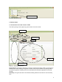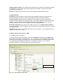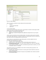
1
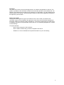
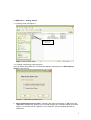
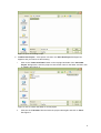
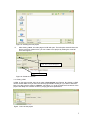
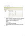
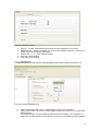
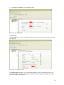
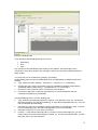
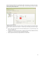
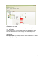
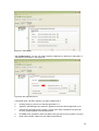
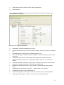
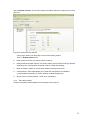
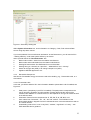
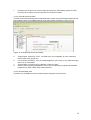
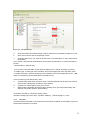
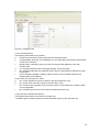
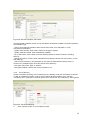
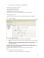
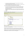
i.
Type: you also need to select what type of the thermal bridge you will add from the drop
down list, and then click “add”. You will then have successfully added one thermal bridge in
the model; others may then be added.
3.3.2
Entering roof/ceiling, wall and floor information
Having set up the different building parts, for each of those parts you need to enter the elements
surrounding that part of the dwelling – the walls, floors, ceiling/roof and which of them have
openings. See Figure 22:
Figure 22: Adding Roof-ceiling element
NB: Click on the “+” adjacent to Building parts to reveal three sub tabs
a.
b.
c.
Roof/ceiling tab: This tab allows you to enter geometrical information about the roof or
ceiling. You can always add more roof/ceiling components by right clicking on the
component name to open a window, then left clicking on the component in that window, as
described in the basic functions instructions in 2.4.1 and 2.4.2
Wall tab: Similar for walls
Floor tab: Similar for floors
NB: In the Geometry form, ‘opening type’ which is included in the “Project & Site” form is also
available to allow the user to add to or edit the existing opening-type.
Create the roof / ceiling: This is done in the roof/ceiling tab. You will be asked to fill in the
parameters that define the roof / ceiling; type, area, U-value, Kappa value, and your description.
See Figure 23 below.
NB: Кm (Kappa m) value, the Кm value (renamed from Cm value) is the effective thermal capacity
of an element (wall, floor, ceiling, etc), given in kJ/m2K. The rules for calculating it can be found in
the CEN standard: prEN 13790:2006.
Type: select from list of the typical options for the roof.
16