1
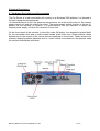
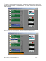
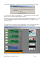
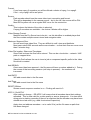
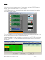
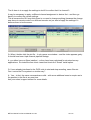
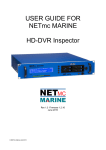
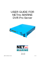
USER GUIDE FOR
NETmc MARINE
DVR Pro Server
Rev 1.03
May 2006
NETmc Marine Pro Server Manual rev1.03
1 of 23
Contents
Section
1
2
2.1
2.2
3
3.1
3.2
3.3
3.4
3.5
3.5.1
3.5.2
4
5
Description
Introduction
System description
Hardware description and connections
Network configuration / DVR interface
Operating Instructions
Software Setup
The Set-up Page
Injecting NAV data
Making a recording
Playing a file
Using Windows Media Player™
Using the NETmc Marine Viewer
FAQS
Appendices
Appendix i – Technical specifications
Appendix ii – Definitions & Abbreviations
Page
3
4
4
NETmc Marine
Dunann Cottage, Turfhill, Cuminestown Road
New Deer,Aberdeenshire
AB53 6TL
TEL. +441771644001
Fax. +441771644005
NETmc Marine Pro Server Manual rev1.03
2 of 23
1 Introduction
NETmc Marine specialises in the design and manufacture of Digital Video Solutions for the
Offshore market and have produced a range of digital video acquisition systems ranging from
single channel digital video recorders to bespoke multi-channel systems for online data
management and retrieval.
When inspecting pipelines with 3 camera views being recorded – the DVR Pro server is
required.
The server is a network attached device, which has to be used in conjunction with 3 NETmc
Marine video recording units (DVR Inspector, Peli or mediaVT spec units).
The server takes control over the 3 encoder units (their local control interfaces are no longer
required), synchronising their outputs, and combining them into one single mpeg compliant
media file (pkt).
The Pro Server can also be fed with a serial string from an online NAV package.
This string is then saved as a flat data file along with the video files (ssn file) – and is also
woven into the mpeg compliant video where is always associated with the video and can be
striped out by any enabled player or GIS system.
This manual details how to interface the Server to 3 DVR Inspector units – and how to setup
the inbound nav string.
NETmc Marine Pro Server Manual rev1.03
3 of 23
2 System Description
2.1 Hardware Description and Connections
The Pro Server is a rack mountable unit running on a Windows 2000 platform. It is housed in
2U high casing and encompasses.
All connections are on the rear panel as shown below, as is the on/off button for the internal
power supply unit and the cooling fan outlet. The power supply switch must be in the on (1)
position for the recorder to function; it is good practice, but not essential, to switch the
internal power supply off when the recorder is not in use.
On the front panel of the recorder is found the main ON button, the receptacle (where fitted)
for the removable drive and a small screen beside which there are 4 black buttons, these
buttons are for the control of the menus that are displayed on the screen. These screens are
primarily displaying status indicators and so, under normal circumstances, the operator need
not concern themselves with them.
NETmc Marine Pro Server Manual rev1.03
4 of 23
2 System Description
2.2 Network configuration / DVR interface
To make use of the Pro Server – it should be connected to 1 or more NETmc video recorders
– either DVR Inspector, Pelicase or mediaVT units.
The video recorders and the Pro Server should all the on the same network – connected via
a switch (100 mbps minimum).
All the network (IP) addresses of the units should be of the same range – by default,
encoders and servers will ship as 192.168.1.xxx - - - where xxx is the last 3 digitals of the
serial number.
The Pro server has a small amount of internal storage – but it is typical to target any
recorded video at a network attached server (NAS) or some other network resource with
sufficient free disk space.
USB storage devices can also be plugged directly into the back of the server.
To view and edit settings – a keyboard / monitor and mouse should be connected to the
server.
A typical hardware configuration would be:
It is good practise to start encoders and NAS units before the Pro Server – so that as the
server starts, it scans for devices it can use. If not started first – it will still find the other
devices – but there will be a short delay as it polls in a timed sequence.
NETmc Marine Pro Server Manual rev1.03
5 of 23
3 Operating Instructions
3.1 Software Setup
When the server boots up – it should auto start the DVR Pro application. If it does not
autostart – the application can be launched by double clicking the desktop icon.
Once started – the DVR Pro application will look like:
Unless the server has been pre-configured with the particular encoders – there will be no
smiling faces ☺ beside each encoder – and the links between the encoder and the server will
be broken.
The next step is to identify to the software which encoders are available – and which one is
being used for which channel.
First step is to see which encoders are available and correctly configured on the network.
From the toolbar on the main screen – click ‘Scan4Devices’.
NETmc Marine Pro Server Manual rev1.03
6 of 23
This will query the network that the Pro Server is attached to see if there are any mediaNET
compliant encoders powered up and configured correctly.
The screen will look something like:
If you cant see all your devices in this list – there is a network problem. Check all cables,
connections and TCP/IP settings on each unit.
As you can see in the above example – there are 3 encoders (type = E) – called dvri79,
dvri80 and dvri81.
There is one server called DVRs – whose external IP address is 192.168.1.149 - - it is a
collator / filer and server (type = CFS) - - - this is what is required to gather, save and control
the slave encoders.
If all encoders are listed – this window can be closed and the encoders associated with each
channel.
NETmc Marine Pro Server Manual rev1.03
7 of 23
To assign an encoder to a particular channel – right click on the white area to the left of the
encoder summary window – in the example below – it’s the left (port) encoder which is about
to be configured.
When the drop down menu appears – select the ‘Assign to mediaVT’ option
NETmc Marine Pro Server Manual rev1.03
8 of 23
The assignment menu will then open:
The channel you are about to assign an encoder to should be highlighted in blue by default
(left / port channel in this example).
With the appropriate channel selected – click on the ‘ASSIGN MEDIAVT’ tab.
click on the line which contains the encoder information you wish to associate with that
channel – in this example, we are going to allocate dvri79 to the left / port channel. When the
line is selected – it is highlighted in blue.
Then click ‘APPLY ASSIGMENT’
NETmc Marine Pro Server Manual rev1.03
9 of 23
A box will pop-up asking you if you want the server to automatically setup the encoder.
This should almost always be answered ‘YES’ - - unless you are an expert user or have
encoders which are permanently assigned to a set task.
Most operators use their encoders for different tasks (e.g. structural inspection etc) – which
makes it essential that the pipeline system is allowed to tweak the configuration to suit - thus pressing ‘YES’
This assignment procedure should be repeated for each channel (centre and right / port) - after which – the main display should have smiling faces next to each channel:
NETmc Marine Pro Server Manual rev1.03
10 of 23
3 Operating Instructions
3.2 The Setup Page
Once the encoders are setup and configured – the final user options are controlled via the
setup pages – accessed by clicking the large setup button beneath the record / stop buttons
on the main screen.
The screen is split into various sections – some for information – some for user changes.
The device section top right – is for information only. It shows / confirms the current
configuration of encoders and server – lists their network names and IP addresses.
The lower half of the screen is interactive – users can click on parameters here to change
what is recorded, what quality / format, what the files are called, how big they are – and
where they are saved.
NETmc Marine Pro Server Manual rev1.03
11 of 23
Format:
If you have mpeg 2 encoders you will be offered a choice of mpeg 1 or mpeg2.
If not – only mpeg1 will be an option.
Source:
Each encoder should use the same video input connection and format.
This will be dependant in the camera source – but in the UK, the source will be PAL
Most ROV system will use a regular BNC co-ax for the connection.
Quality:
This is where the bitrate of the video is selected.
If mpeg 2 encoders are available – the choice if bitrate will be higher
Video Storage Format:
Material from the Pro Server has to be pkt – as this identifies to enabled player that
the files contain multiple camera views and navigation data.
Maximum Segment Size:
No one want huge video files. They are difficult to edit / store and distribute.
Most users select 300 seconds as the max duration – so that their files are never more
than 5 minutes long.
Video File location, Share and Templates:
Store Path is where the files will be stored. This can be a local drive – network UNC
path or mapped drive.
Videofile Prefix allows the use to insert a job or component specific prefix to the video
file which is created.
Add SEQNO:
Once record has been pressed – the file name will have a number added to it. During
the course of that recording session (until stop is pressed) – the numbers will
increment.
Add DATE:
Will add current date to the file name
Add Time:
Will add current time to the file name
RESET SSN=xx
Shows current sequence number in xx. Clicking will reset to 0
APPLY / Re-APPLY
After making a change – RE-APPLY will ensure that all encoders have their settings
refreshed. This is most valid for a video quality or source change etc. It is also worth
doing prior to starting recording if there is a suspicion that the encoder may have been
altered since last used (e.g. used for structural inspection)
Apply does not address encoders – so is useful if its just the file name or path that
has been changed
NETmc Marine Pro Server Manual rev1.03
12 of 23
3 Operating Instructions
3.3 Injecting NAV Data
If available – it is good practise to inject the Pro Server with a real-time navigation string from
the survey NAV computer.
This has 2 effects. Firstly – the string is converted into a flat file and related to the video
filenames – stored in a .ssn file – which will be found in amongst the video files.
It also embeds the navigation information directly into the mpeg headers. This allows
enabled players to read and display those navigation records during the replay of the video.
It also allows enabled GIS packages to strip the information out of the video files and
reconstruct a relational database of navigation positions Vs video file and position within that
file.
The server requires a bespoke string to be setup as an output on the Survey computer. It
should be set to 9600,8,N,1 - -with an update rate of around 1Hz- - and plugged into the
9way serial connector on the rear of the Pro Server – in NULL-modem configuration (pin 2>3, pin 3->2, pin 5->5).
(normally – the position being output is the reference point of the camera on the vehicle
which is being recorded).
The data string should be configured as:
1
2
3
4
5
6
123456789012345678901234567890123456789012345678901234567890
dd mm yy tt:tt:tt.tt eeeeee.eennnnnnn.nnkkk.pppdddd.cc
DATE
TIME
EASTING NORTHING
KP
DCC
EXAMPLE:
28 03 00 15:58:28.22 556492.196342211.19 -9.336-720.54
DECODE
28/3/00
15:58:28.22
Easting: 556494.19
Northing: 6342211.19
KP: -9.336
DCC: -720.54
NETmc Marine Pro Server Manual rev1.03
13 of 23
3 Operating Instructions
3.4 Making a recording
With everything configured – the path for the video and the file naming conventions set –
actually making a recording is very simple.
Simply click the “record” button on the main control panel:
If the unit successfully starts recording – the button will indent, and the counter will start to
increment:
If the button refuses to indent – it is because it cannot start recording for some reason.
Typically this will be because the path name for the video doesn’t exist – or the drive is full or
something along those lines.
NETmc Marine Pro Server Manual rev1.03
14 of 23
On clicking record – you may have a pop-up message appear:
You may have intentially decided to start recording without all encoders being active - - this
maybe perfectly valid (as you only have 2 encoders for example). If its not your intention –
you need to go back through the assignments to see if you have any configuration errors.
NETmc Marine Pro Server Manual rev1.03
15 of 23
3 Operating Instructions
3.5 Playing a file
Playing a multichannel pkt file with NAV data can only be done properly once the NETmc
filters have been installed.
The Pro Server will have these installed by default - - but the easiest way to install these
filters on another computer is to install our client viewer – which freely available from our
website.
3.5.1 Using Mediaplayer
If you navigate to the folder which contains the pkt files using windows explorer – you can
double click a pkt – which will automatically open windows media player to open the file.
If the pkt has multiple video channels – 2 slave windows will automatically open which in
conjunction with the main mediaplayer console – will show all 3 images perfectly
synchronised.
(you will have to arrange the windows manually on your desktop to get the layout that suits
your environment).
Using the scroll bar on windows mediaplayer will skip through all 3 video channel with the
same ease as navigating 1.
If the pkt file has nav data embedded in it – an error may be observed – this is because
media player has no window to render the NAV data into:
NETmc Marine Pro Server Manual rev1.03
16 of 23
To prevent this message appearing – you need to use a viewer which has a facility to replay
the nav data – as well as the video.
NETmc Marine Pro Server Manual rev1.03
17 of 23
3.5.2 Using NETmc Marine Viewer
Alternatively, the video can be viewed in our free client viewer.
If the 3head option if selected during install – the player will open in a mode optimised for
pipeline video.
Simply use the folder icon to browse for pkt file – select the one you want to open – and the
click play to run the video.
The nav data is display in the window above the centre picture – and can be seen to update
as the video runs.
NETmc Marine Pro Server Manual rev1.03
18 of 23
4 FAQs
Q. My unit has a broken link between one of the encoders – and says CFG ERR under an
encoder. I don’t know what it means – or how to remove it.
A: CFG ERR is drawing your attention to the fact that the setting which have been applied,
aren’t right for proper operation.
This is most likely due to there not being a unique channel associated to each recorder – e.g.
you have used the same encoder for more than one channel.
In the above example – by right clicking next to the encoder with the CFG ERR and selecting
ASSIGN TO MEDIAVT - - we can see that the problem here is that we have 2 units trying to
use channel 1.
NETmc Marine Pro Server Manual rev1.03
19 of 23
The fix here is to re-apply the settings to dvri81 to confirm that it is channel 3.
It may be necessary to apply a different channel assignment to device first – and then go
back in to confirm the correct settings.
This is because the GUI may think there is no need to change anything (because the change
was done via remote control or a different console etc) so wont re-apply the settings if it
believes them to be the same.
Q. When I double click the pkt file – it only opens one window – and the video appears gerky.
It should have been triple channel pipeline footage.
A. you either have no filters installed – or they have been optimised for structural survey
applications. Re-install the free client viewer and check the “3head” install option.
Q. I have already interfaced to the DVRi units to start and stop recording, name files etc.
Can I control the Pro system in a similar way ?
A. Yes – in fact, the same commands are valid – with some additional ones to enquire as to
the position in the file at any one time.
Ask your sales / support contact for more details.
NETmc Marine Pro Server Manual rev1.03
20 of 23
Q. Some times when I first play my multi channel video – one of the windows is blank. I’ve
noticed that if I move the window – a picture appears in it. Why is this ?
A. Your computer has hardware acceleration on the VGA card – it is trying to grab the handle
from that video window and assist in its render. From the START button, select RUN and
enter dxdiag and click run. When the window opens – pick display (or display1) and ensure
the DirectX Features are all disabled:
NETmc Marine Pro Server Manual rev1.03
21 of 23
Appendix i
Technical Specifications
Power Requirements
100 - 260 Vac, 50 - 60 Hz
Power Consumption
180w
Operating Temperature
10 - 35 Degrees
Non-operatingTemperature
-10 - 60 Degrees
Operating Humidity
5-95% RH non-condensing
Non-operating Humidity
5-95% RH non-condensing
Operating Shock (read)
65G, 2ms
Non-operating Shock
250G, 2ms
Operating Altitude
-305m – 3,050m
Non-operating Altitude
-305m – 12.200m
Operating Vibration
Non-operating Vibration
Linear 20-300Hz, 0.75G (0 to peak)
Random 10-300 Hz, 0.004g2/Hz
Low frequency 5-20 Hz, 0.195 inches (double amplitude)
High frequency 10-300Hz, 5.0G (0 to peak)
Dimensions
482(W) x 88.5(H) x 455(D) (2U case)
Weight
15kg
Network Support
10 / 100 Base T & 10/100/1000
Serial Ports
9 Way D-Type for serial navigation
Storage and shipping
After overnight road freight the units should be left at room temperature for 24 hours before
powering on.
After air freighting the units should be left at room temperature for 48 hours before powering
on.
NETmc Marine Pro Server Manual rev1.03
22 of 23
Appendix ii
Definitions & Abbreviations
Definitions
DVRi
DVR Inspector Single Channel Digital Video Recorder
Abbreviations
ASCII
American Standard Code International Interchange
DB
Database
DLT
Digital Linear Tape
DRS
Digital Review Suite
DVR
Digital Video Recorder
HTML
Hyper Text Mark-up Language
MPG
Moving Pictures Expert Group File extension for a video file
MPEG1
Industrial recording format, controlled by the Moving pictures expert group
Payable on all Windows operating systems win95 ->
PKT
Packet File Extension
PAL
Phase Alternation by Line – the European video format
NTSC
National Television Standards Committee – American / Asian video format
JPEG
Joint Photographic Experts Group
Mbps
Mega bits per seconds – rate of video encoding
QC
Quality Control
USB
Universal Serial Bus
Store path Local on hard-disk where the video will be placed
SVHS
Super Video Home System
TIFF
Tagged Image File Format
End of Document
NETmc Marine Pro Server Manual rev1.03
23 of 23