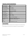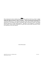
1
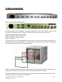
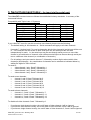
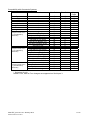
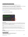
USER GUIDE FOR
NETmc MARINE
videoTXT
Rev 10.1 Firmware version 6.04, 6.06
January 2013
videoTXT_man rev 10.1 January 2013
© NETmc Marine Ltd 2012
1 of 40
Contents
1. Introduction..........................................................................................................................3
2. Rear connections.................................................................................................................4
3. Serial Command Index - for input via the serial port. ...........................................................6
4. Keyboard Command Index ..................................................................................................8
5. Menu Structure ..................................................................................................................11
5.1: Help.............................................................................................................................11
5.2: Time / Date Settings....................................................................................................12
5.3. Text size and area settings .........................................................................................16
5.4: Text shade settings. ....................................................................................................19
5.5: Channel title settings...................................................................................................21
5.6: Display offset settings .................................................................................................23
5.7: Serial port settings and LAN set-up.............................................................................24
Option 1: Use Serial port 2 or Network Interface.........................................................24
Option 2: Serial port 3 settings....................................................................................25
Option 3: Network interface settings ...........................................................................25
5.8: String parser settings ..................................................................................................27
5.9: Analogue interface settings.........................................................................................29
6. Overlay Manager ...............................................................................................................35
7. Troubleshooting .................................................................................................................36
8. Definition of Terms.............................................................................................................37
9. How to contact NETmc Marine Support.............................................................................38
Appendix 1: Technical Specifications ....................................................................................39
NETmc Marine Ltd
New Deer, Turriff, Aberdeenshire
AB53 6TL
Scotland
TEL. +44 1771 644001
FAX. +44 1771 644005
EMAIL. [email protected]
videoTXT_man rev 10.1 January 2013
© NETmc Marine Ltd 2012
2 of 40
1. Introduction
NETmc Marine’s videoTXT is a robust solid state overlay unit – capable of overlaying text onto PAL
or NTSC video signals. The videoTXT will detect which type of signal is present automatically. Note
that if no signal is detected, the videoTXT will default to PAL settings.
Housed in a 1U rack mount case – the videoTXT is capable of placing text on up to 4 separate
unsynchronised video signals. Data can be input via PS2 keyboard or serial port.
The videoTXT is able to decode and display some equipment specific strings (GPS units / ROV
controllers etc). Contact NETmc Marine Support to discuss how to get your equipment on the
supported list.
Up to 1656 characters* can be displayed on the screen in 4 selectable font sizes and 9 selectable
font shades. (*small font 1656 PAL, 1380 NTSC)
The videoTXT has an internal real time clock (RTC) – which allows time and date to be displayed on
the screen without being fed from an external source.
The firmware can be updated in situ via serial port 2. Please contact NETmc Marine Support for
more details.
Available models:
Single Video channel unit
Dual Video channel unit
Triple Video channel unit
Quadruple Video channel unit
Options (available with all models):
Analogue interface settings
Additional (third) serial port
LAN (local area network) option
NOTE: The third serial port is active only if this additional option has been purchased. Any data input
to this third serial port is restricted to the bottom half of the screen.
Upon powering-up the videoTXT the following screen is displayed, confirming which model is present
(single, dual, triple or quadruple channel) and which firmware version the unit is using.
videoTXT_man rev 10.1 January 2013
© NETmc Marine Ltd 2012
3 of 40
2. Rear connections
Rear panel for units with LAN option
External data feeds from a navigation or inspection package (e.g. Eiva / QPS / Starfix / Coabis / Pisys
etc) can be connected to Serial 1, Serial 2 or Serial 3 (if this option has been purchased).
A typical / recommended set-up would be:
Serial 1: Navigation data / custom string
Serial 2: Inspection component ident
Serial 3: CP value
The serial inputs are 100% independent, each functions as if it were a transparent screen sized text
area laid on top of each video channel – so a “clear screen” command sent on Serial 2 will not delete
any text being fed from Serial 1 (see diagram below).
NOTE: The keyboard and internal clock output to the same overlay layer as Serial 2: therefore if the
keyboard and/or internal clock are to be used, avoid any external inputs to Serial 2.
If the Serial 3 option has been purchased, Serial 2 and 3 inputs share the same layer: Serial 2 uses
the top half of the screen, Serial 3 the bottom half.
videoTXT_man rev 10.1 January 2013
© NETmc Marine Ltd 2012
4 of 40
When making a cable to link between videoTXT and a PC – this should be a cross over (null modem)
configured as:
PC
2
3
5
videoTXT
3
2
5
Data should be sent to the videoTXT as:
9600 Baud
8 bit
No parity
1 stop bit
Note: THIS EQUIPMENT MUST BE EARTHED.
videoTXT_man rev 10.1 January 2013
© NETmc Marine Ltd 2012
5 of 40
3. Serial Command Index - for input via the serial port.
The videoTXT command structure follows the established industry standards. A summary of the
commands follows:
Compatibility with Taylor Lann / C-Systems
Function
Clear Screen
Cursor Right
Cursor Up
Cursor Down
Cursor Left
Home Cursor
Line Feed
Carriage return
Hex Code
10
11
12
13
14
15
0A
0D
Dec Code
16
17
18
19
20
21
10
13
Key Code
^P
^Q
^R
^S
^T
^U
^J
^M
If your videoTXT is set for use with more than one channel please note the following:
- The default setting is: All channels on. Serial commands will apply to all video channels.
-
Hex code 7 / decimal code 7 is used to determine which video channel(s) serial input will be sent
to. This command can be issued on both serial port one and serial port two and acts
independently for each. i.e. the serial input can be sent through serial port one to one video
channel or a combination of channels, and a different serial input can be sent through serial port
two to a different video channel (or combination of channels.)
-
For all settings, two bytes need to be sent: 7 followed by another digit to select which video
channel(s) should apply. Any combination of channels can be selected as indicated below by
adding the digits for each channel:
To send to:
o
video channel 1 only: Send 7 followed by 1.
o
video channel 2 only: Send 7 followed by 2.
o
video channel 3 only: Send 7 followed by 4.
o
video channel 4 only: Send 7 followed by 8.
To send to two channels:
o
channel 1 and 2: Send 7 followed by 3.
o
channel 1 and 3: Send 7 followed by 5
o
channel 1 and 4: Send 7 followed by 9
o
channel 2 and 3: Send 7 followed by 6
o
channel 2 and 4: Send 7 followed by 10
o
channel 3 and 4: Send 7 followed by 12
To send to three channels:
o
channels 1, 2 and 3: Send 7 followed by 7.
o
channels 1, 2 and 4: Send 7 followed by 11
o
channels 1, 3 and 4: Send 7 followed by 13
o
channels 2, 3 and 4: Send 7 followed by 14
To disable all video channels: Send 7 followed by 0.
-
-
If you have a triple-channel overlay, the on/off state of video channel 4 will be ignored.
If you have a dual-channel overlay, the on/off state of video channels 3 and 4 will be ignored.
If you have a single-channel overlay, the on/off state of video channels 2, 3 and 4 will be ignored.
videoTXT_man rev 10.1 January 2013
© NETmc Marine Ltd 2012
6 of 40
Compatibility with Oceantools Systems
Function
Subfunction
Hex Code
Dec Code
n/a
n/a
n/a
n/a
n/a
n/a
n/a
n/a
10
11
12
13
14
15
0A
0D
00
01
02
03
04
05
06
00
01
01
02
03
04
05
06
00
09
01
02
03
16
17
18
19
20
21
10
13
0
1
2
3
4
5
6
0
1
1
2
3
4
5
6
0
9
1
2
3
Clear Screen
Cursor Right
Cursor Up
Cursor Down
Cursor Left
Home Cursor
Line Feed
Carriage return
Time *
(2 bytes must be sent –
e.g. 00 followed by
parameter)
Set time to Top Centre
Set time to Bottom Centre
Set time to Top Left
Set time to Top Right
Set time to Bottom Left
Set time to Bottom Right
Set time to Off
Date *
(2 bytes must be sent –
e.g. 01 followed by
parameter)
Set date to Top Centre
Set date to Bottom Centre
Set date to Top Left
Set date to Top Right
Set date to Bottom Left
Set date to Bottom Right
Set date to Off
Font
(2 bytes must be sent –
e.g. 09 followed by
parameter)
Set font to small
Set font to medium
Set font to large
Key
Code
^P
^Q
^R
^S
^T
^U
^J
^M
^I
^A
^B
^C
* Serial port 2 only
Neither Time, Date or Font changes are supported on Serial port 3.
videoTXT_man rev 10.1 January 2013
© NETmc Marine Ltd 2012
7 of 40
4. Keyboard Command Index
The keyboard must be connected to the front of the videoTXT prior to power-up.
The videoTXT is designed to work with any PS2 keyboard. A USB keyboard used via a PS2 adapter
should also work but designs vary and so NETmc Marine cannot guarantee this.
Text can be drawn on the screen by typing on the keyboard in the regular manner.
Caps Lock and Shift keys are supported for capital letters and punctuation characters.
Select the position on the screen where the text should appear by using the arrow keys.
Backspace is used to erase text
F keys: shortcut keys (see summary below)
ESC takes the user out of the menu system.
Scratch mode
Upon first powering up the unit, “scratch” mode is entered. Text will be displayed on the screen as
typed into the keyboard. This text is lost if any other command is carried out (for example entering
the menu system) or if the videoTXT is switched off.
The font size and shade, and offset settings can be altered using the menu system (via F1) – see
below.
The default setting upon power up is that this text is displayed on all video channels. Text can be
disabled from any one or more channels by using shortcut key commands (see below).
NOTE: In scratch mode (and in this mode only) the “Insert” function on the keyboard has had to be
disabled.
Stored text
Four different pages of text can be stored for future use. These are activated by the use of the F5,
F6, F7 and F8 shortcut keys.
To set up your stored text:
1: select the text size required using the Control Menu option 3.
2: select the required shortcut key (F5 or F6 or F7 or F8)
videoTXT_man rev 10.1 January 2013
© NETmc Marine Ltd 2012
8 of 40
3: type in the text required.
The text is recorded automatically and is displayed every time the same shortcut key is pressed.
Even if the videoTXT is powered off, the text is stored.
It is possible to have different text shades and sizes on each page. These are chosen through the
menu system. (Select F4 to return to scratch mode and then F1 to enter the menu system – see
below for more details.)
NOTE: changing the text size on a stored page also deletes the text on that page. Changing the text
shade can be carried out at any time (before or after the text has been created).
Channel titles:
A short title can be set up for display on each video channel in use. For example, when a triple
channel videoTXT is in use, the user could display “Diver 1” on the first video channel, “Diver 2” on
the second video channel and “Diver 3” on the third video channel. Channel titles are also retained if
the videoTXT is powered off.
NOTE: On a single channel overlay only the first title is displayed.
To set up channel titles use option 5 of the Control menu. (See below for more details).
Cursor position:
The cursor flashes at its current position to facilitate keyboard use. This may be on top of time/date
(as in the example below) or some text. If the keyboard is not used, the flashing cursor will disappear
after approximately 10 seconds.
videoTXT_man rev 10.1 January 2013
© NETmc Marine Ltd 2012
9 of 40
Summary of shortcut key commands:
F1:
Brings up the Control Menu (see below for more details). Note: This key only functions
when in scratch mode.
F2:
Clears the display; if on a stored page, the page memory will also be cleared.
Shift-F2: Clears only the Serial Port 1 display.
F3:
Enables/disables the Serial Port 1 display.
F4:
Selects scratch page (freestyle, volatile text)
F5:
Selects stored page 1
F6:
Selects stored page 2
F7:
Selects stored page 3
F8:
Selects stored page 4
Ctrl-F5: Clears stored page 1 (Note: This and the next 3 key commands can be used whichever
page the user is currently on.)
Ctrl-F6: Clears stored page 2
Ctrl-F7: Clears stored page 3
Ctrl-F8: Clears stored page 4
Ctrl-1:
Enables/disables the display of keyboard input on video channel 1
Ctrl-2:
Enables/disables the display of keyboard input on video channel 2
Ctrl-3:
Enables/disables the display of keyboard input on video channel 3
Ctrl-4:
Enables/disables the display of keyboard input on video channel 4
Ctrl-I:
Inserts an empty row at the current cursor position
Ctrl-D:
Deletes the row at the current cursor position
Insert:
Toggles between overstrike and insert modes (only available when on a stored page)
Delete:
Deletes the character underneath the cursor (only available when on a stored page) and
moves the remainder of the row to the left.
Backspace:
Deletes the character to the left of the cursor; if on a stored page, this key moves the
remainder of the row to the left
Return:
Begins a new line on the display
Cursor keys: Move the cursor in the direction of the arrows.
Page up:
Moves the cursor to the upper left of the screen
Page down:
Moves the cursor to the lower right of the screen
Home:
Moves the cursor to the start of the current row
End:
Moves the cursor to the end of the current row
videoTXT_man rev 10.1 January 2013
© NETmc Marine Ltd 2012
10 of 40
5. Menu Structure
The user can enter the menu system by pressing F1, whilst in scratch mode.
NOTE: The example shows a screen where no input signal is connected. If a signal is
connected the menu will be displayed over this signal.
In each menu, type the appropriate number to select that option. Press the Escape key to return to
normal display.
Note that the menu options are dependent on the model of videoTXT that has been chosen. Menu
option 9: Analogue interface settings will only be shown if this option has been purchased with your
videoTXT.
The menu options are described below, with screen shots of the pages the user can expect to see.
5.1: Help
This option contains some basic operational and setup tips
videoTXT_man rev 10.1 January 2013
© NETmc Marine Ltd 2012
11 of 40
5.2: Time / Date Settings
Use this menu to change the time on the internal clock, or to change the position of the time and date
on screen. It is also possible to select either UK or US date format and synchronise the time with
GPS:
Option 1: Check current time setting. (An example screen is shown here)
Option 2: Set current time and date
videoTXT_man rev 10.1 January 2013
© NETmc Marine Ltd 2012
12 of 40
Option 3: Select date format
Once a format has been selected, the user will see a screen similar to the one below:
Option 4: Select current time zone.
This will be necessary if you wish to synchronise the time with a GPS signal. Examples are shown
below.
videoTXT_man rev 10.1 January 2013
© NETmc Marine Ltd 2012
13 of 40
Option 5: Sync time with NMEA (xxGGA)
It may be desirable to have the internal clock in the overlay synchronised with a GPS receiver - to
ensure information displayed on the overlay matches the survey position time.
With an NMEA string at 4800 baud being input to serial 1 of the overlay, and the String Parser
settings enabled (see section 5.7) the steps below will enable time sync.
Notes on the 2 GPS systems: the GGA signal is available almost everywhere but the signal carries
only the time and not the date, therefore the date may need to be correctly manually. The RMC
signal carries both the date and the time, but depending on the location of the vessel, may not be
available.
If the following message appears the string parser settings may need to be adjusted: return to Option
7 of the Control Menu.
videoTXT_man rev 10.1 January 2013
© NETmc Marine Ltd 2012
14 of 40
Option 6: Sync time with NMEA (xxRMC)
If the following message appears the string parser settings may need to be adjusted: return to Option
7 of the Control Menu.
Option 7: Time and date display settings
Time and date can be displayed in different positions on the scratch and on each of the four stored
pages.
videoTXT_man rev 10.1 January 2013
© NETmc Marine Ltd 2012
15 of 40
5.3. Text size and area settings
It is possible to set different text sizes for the scratch page and for each of the four stored pages:
NOTE: Changing the text size on a stored page also deletes the text on that page. Therefore it is
important to choose the text size first and then set up the page with the required text.
Choose which page you wish to set the text size for, then select the size required from the options
below: If you are using an NTSC signal the appropriate sizes will be displayed for this signal.)
For reference, the four sizes available are:
PAL
Small font:
69 columns
24 rows
Default font:
52 columns
19 rows
Medium font:
34 columns
19 rows
Large font:
32 columns
7 rows
videoTXT_man rev 10.1 January 2013
© NETmc Marine Ltd 2012
NTSC
20 rows
16 rows
16 rows
6 rows
16 of 40
NOTE: Changing the text size will also affect the position of any offset that has been set. For this
reason if the text size is changed, the following message will be displayed and the offset position is
reset to (1,1) so that the user can re-choose the optimum position. See section 6 below.
Option 7: Display overscan settings
What is overscan?
Early monitors / televisions varied in their displayable area because of manufacturing tolerance
problems. There were also effects from the early design limitations of linear power supplies, whose
DC voltage was not regulated as well as in later switching-type power supplies. This would cause the
image to shrink when AC power 'browned out', as well as a process called blooming, where the image
size increased slightly when a brighter overall picture was displayed. Because of this, TV producers
could not be certain where the visible edges of the image would be. In order to cope with this, they
defined three areas:
Title safe:
An area visible by all reasonably maintained sets, where text was certain not to be cut
off.
Action safe: A larger area that represented where a "perfect" set (with high precision to allow less
overscanning) would cut the image off.
Overscan: The full image area to the electronic edge of the signal.
videoTXT_man rev 10.1 January 2013
© NETmc Marine Ltd 2012
17 of 40
Modern LCD monitors don’t suffer from the same problems which created the need for overscan in
the first place - so under normal settings, users may feel that there is wasted area around the screen
which the overlay text cannot reach.
For this reason, an option has been created to enable the overscan region, effectively allowing the
text to write over a larger area.
It should be noted that if overscan is enabled, all the overlaid text may not be visible if CRT monitors
are used.
When overscan is enabled, the screen area available to the overlay increases (annotated as PAL+
and NTSC+) - making the number of characters on each row and column:
With overscan enabled, the four sizes available are:
NTSC
PAL
Small font:
80 columns
27 rows 23 rows
Default font:
60 columns
21 rows 17 rows
Medium font:
40 columns
21 rows 17 rows
Large font:
36 columns
7 rows
6 rows
videoTXT_man rev 10.1 January 2013
© NETmc Marine Ltd 2012
18 of 40
5.4: Text shade settings.
Separate shades can be selected for the scratch and each of the four stored pages.
Examples of the 9 text shades available are shown overleaf:
Note: the example shown is on a striped background to best
display the range of shades in this printed manual.
When the number corresponding to each text shade is typed, the relevant font shade is immediately
shown on screen. Some examples of these fonts shown over a video signal are as follows:
1. Normal white text
videoTXT_man rev 10.1 January 2013
© NETmc Marine Ltd 2012
4. Bold black
19 of 40
5. White on black background
6. Black on white background
7. Outlined white text
8. Outlined black text
9. White on transparent
videoTXT_man rev 10.1 January 2013
© NETmc Marine Ltd 2012
20 of 40
5.5: Channel title settings
This option enables brief titles to be set up which will be displayed on each separate screen.
NOTE: All 4 titles will only be displayed when a quad channel overlay is in use. With a single channel
overlay, only the first title (text one) will be displayed; with a dual channel overlay only texts one and
two are displayed, with a triple channel overlay texts one, two and three are displayed.
Option 1: Enter text for titles
Simply type in the text required.
The following screen shows an example where the text for three channels has been entered:
To delete the title on any video channel, simply delete the text for the relevant channel on the above
menu screen. In the example below no title has been set for video channel 1:
videoTXT_man rev 10.1 January 2013
© NETmc Marine Ltd 2012
21 of 40
Option2: Set title positioning
The following screen shows an example of a scratch page with the channel title enabled.
videoTXT_man rev 10.1 January 2013
© NETmc Marine Ltd 2012
22 of 40
5.6: Display offset settings
This option enables the user to position the text being sent to the videoTXT via the serial ports. This
is useful if you cannot change how your serial string device outputs its data. The offset for the scratch
page can also be set here.
Examples of this screen where the positioning has been changed are shown below:
NOTE: If the text size is changed, the offset will be returned to the default (1,1) position. This is
because changing the text size will alter the available number of rows / columns, which may result in
the previously saved offset becoming invalid.
videoTXT_man rev 10.1 January 2013
© NETmc Marine Ltd 2012
23 of 40
5.7: Serial port settings and LAN set-up
Option 1: Use Serial port 2 or Network Interface
If the LAN option has been purchased, then the LAN interface works as a replacement to Serial Port
2. The user can select to either use Serial Port 2 or the LAN.
Once the second option “Use network interface” has been selected, then a third option “Network
interface settings” becomes visible:
videoTXT_man rev 10.1 January 2013
© NETmc Marine Ltd 2012
24 of 40
Option 2: Serial port 3 settings
(Note: these settings are visible if the 3rd Serial Port option has been purchased.)
When enabled, data input to serial port 3 will appear on the bottom half of the screen.
Serial port 2 will then be limited to the top half of the screen.
Option 3: Network interface settings
(Note: these settings are visible if the LAN option has been purchased, and the option “Use Network
Interface” has been selected in the Serial port 2 settings.)
The user is guided through a series of steps to set up the LAN interface.
Firstly, the user selects the TCP port on which the serial server will operate:
videoTXT_man rev 10.1 January 2013
© NETmc Marine Ltd 2012
25 of 40
Secondly, the user specifies the network name for the overlay:
Then, the user chooses the method used by the overlay to determine its address settings
(DHCP or static):
videoTXT_man rev 10.1 January 2013
© NETmc Marine Ltd 2012
26 of 40
Next, the user specifies the IP settings which will be used by the overlay:
Finally, the user is asked to press Return to accept the changes:
5.8: String parser settings
videoTXT_man rev 10.1 January 2013
© NETmc Marine Ltd 2012
27 of 40
Option 1: Select parser string
NOTE: videoTXT is able to decode and display some equipment specific strings (GPS units / ROV
controllers etc), connected to Serial 1 only. Contact NETmc Marine Support to discuss how to get
your equipment on the supported list.
Option 2: Set display positioning
If you have a GGA compliant GPS signal available, it can be input to serial 1 and enabled using this
menu, to display latitude and longitude on screen.
NOTE: GPS data should be 4800,8,N,1)
An example of a GPS display is shown below:
videoTXT_man rev 10.1 January 2013
© NETmc Marine Ltd 2012
28 of 40
NOTE: Should the GPS signal disappear for 4 seconds or more the following warning message will
appear:
5.9: Analogue interface settings
(Note: these settings are available as an extra option on all models)
In most cases, data is sent to the overlay via a RS232 data link as a string of ASCII characters - but
some sensors are not able to generate this type of output. Instead they output a voltage which is
relative to the value or status of the sensor. This voltage changes as the status or conditions change.
These analogue signals can be interfaced to the VideoTXT by means of the optional 4-channel
analogue to digital converter (ADC) board. Each channel is separately configurable for scaling,
voltage offset and screen position and can be labelled with a descriptor and unit.
Input 1 (referred to as CP) has a precision isolation amplifier fitted, allowing the measurement of
signals with floating ground - which is particularly suitable for any application where there is a risk of
erroneous voltages, e.g. CP measurements. The isolation also gives the circuits a level of protection
from over voltage (up to 1000v) and short circuit.
Inputs 2-4 share a common reference, e.g. ground - or a 0V line, and are protected to around 50v.
The following sections explain the menu options, concluding with a worked example for reference.
To access the relevant menu, from the menu screen (press F1 while in scratch mode), select option
8: Analogue interface settings:
5.9.1 Analogue display settings
This screen allows you to choose which of the 4 channels should be displayed on screen, and to set
the maximum voltage values for each channels.
videoTXT_man rev 10.1 January 2013
© NETmc Marine Ltd 2012
29 of 40
For each channel, select the maximum voltage value that might be applied to the analogue input to
give you a full scale reading from the analogue to digital converter. There are 3 different input
ranges: 0 to +2.5V, 0 to +5V and 0 to +10V.
The channels are controlled by the keys described on the screen, so key “C” switches on the CP
channel, whilst key “1” switches on Channel 1. Furthermore, the same key toggles through each of
the voltage settings. For example, in a new machine the display settings will appear as shown in the
example above. Press C once to display the CP channel with +2.5V, press C again to select +5V, C
again to select +10V. Similarly, press 1 repeatedly to toggle between the voltage options for
channel AUX 1; press 2 repeatedly to toggle through the options for channel AUX 2 and so on.
It is possible to have any combination of the channels selected (including none or all of the channels).
Example with CP and channel 1 selected
Example with channels 1 and 2 selected
videoTXT_man rev 10.1 January 2013
© NETmc Marine Ltd 2012
Example with no channels selected
Example with channels 1 and 3 selected.
30 of 40
5.9.2 Analogue input calibration
Note: The factory default settings will give sensible outputs and can be left as they are.
For advance users who wish to fine-tune the calibration:
This sub-menu allows the user to set the A-D converter so that the full scale output of the A-D
corresponds to the full scale input voltage applied to the unit. This is done by changing the values for
each channel so that the ADC uses all 4095 available levels.
The default settings can be retrieved at any time by pressing the Backspace key. Press ENTER to
accept these options. Press ESC to return to the settings set by the user.
Note: This option can only be selected for those channels which have already been selected under
option 8.1 Analogue Display Settings. The input range displayed is that which was selected on the
Display Settings page.
Examples:
Reference trim
This is used to fine tune the output of the A-D converter after setting the Scaler setting. However,
before making any adjustments the reference trim should be set to ZERO. In order to increase the
reading from the system towards 4094 the reference trim needs to be adjusted DOWN. If an overrange warning appears, the reference trim should be adjusted UPWARDS.
Scaler setting
This is used to tune the output of the A-D converter, so that the maximum analogue voltage you
intend to apply corresponds with the maximum scale on the converter. The biggest number the A-D
outputs is 4095. When you change input range, the scaler setting is automatically changed so that
the maximum voltage input of that range equates to an A-D output of 4095, e.g. on 0->5v range, 5
volts = 4095. If the largest signal you will ever apply is 4 volts, you still need to be on the 0->5v
videoTXT_man rev 10.1 January 2013
© NETmc Marine Ltd 2012
31 of 40
range, but it would be desirable to adjust the scaling so that 4v equates to 4095, so you get the full
range and accuracy available.
The scaler setting should be adjusted to close to, but not exceeding 4094 (else an over-range
warning will show.) E.g. after using the scaler settings, the A-D output may be 4093 – adjusting the
reference trim downwards will bring it up to 4094. Note: If set to 4095 the system cannot
distinguish between this and an over-range so only go up to 4094.
The scaler setting option is not available on the CP channel.
ADC output
This shows the raw value that is being returned by the converter.
Press the ENTER key to save the settings.
Then select ESC to return to the analogue menu.
5.9.3 Analogue input configuration
The analogue input configuration screen allows you to set up the parameters, as you want to see
them on screen. The prefix, suffix, gain, offset, (x,y) and digits before and after the decimal point can
all be adjusted.
For example to adjust the configuration of the Channel Aux 1, press the “1” key. The cursor appears
in the Prefix field. Any text can be entered here. Press “Enter” and the cursor moves to the Suffix
field. Again any text can be entered. Press “Enter” again and the cursor enters the */ field. Tab
between the * (multiply) and / (divide options). Press “Enter” to advance to the next field, and so on.
Gain
The gain specifies a value in which the value from the A to D converter will be either multiplied or
divided by in order to give a more meaningful display. For example the output will always be in the
range 0 to 4095. However if degrees are being measured, the result should be in the range 0 to 360.
In this case the gain should be set to “/ 11.375” (as shown in the example above.) Then an output of
4095 will be displayed as 360.
Offset
The offset will be is added or subtracted to the new value received after the gain adjustment.
An offset might be used for example if voltage is being measured: to display values in the range -2.5
to +2.5 (instead of 0 to 5) an offset of -2.5 would be entered.
videoTXT_man rev 10.1 January 2013
© NETmc Marine Ltd 2012
32 of 40
(X,Y)
This sets the position of the display on screen
In the example above, display settings for channel AUX 1 are displayed on screen, in the position of
X=8, Y =9.
The text displayed for an output of 4095 would be:
Heading 360.00 Deg
In the example above, display settings for channel AUX 1 and for the CP channel are displayed on
screen. The CP is shown in the top left corner, the AUX 1 channel readings in the position of X=8, Y
=9.
Example A-D setup procedure
An ROV has a gyro compass system which outputs a voltage between 0 and 3.6 volts, which
relates to 0 - 360 degrees of vehicle heading.
1)
2)
3)
4)
5)
6)
7)
8)
9)
10)
11)
12)
13)
Select which input to use. It is a low risk input (not requiring the isolation of the CP
input) so use first available AUX pair.
Open Analogue Display Settings menu. As max voltage is 3.6, the 0->5v range must be
used. Set the range for AUX1 to +5V.
Open the Analogue Input Calibration menu.
Hit 'backspace' to clear any previous setups and take the figures back to defaults.
Set compass to output its maximum value (or simulate using bench supply)
Adjust the scaler settings so that raw ADC output is as close as possible to but not
exceeding 4095. If you over adjust, the A-D output will become saturated and the 'over
range' warning will be displayed.
Use the reference trim to fine tune the output to be 4095.
Hit return to save the settings, then open the Analogue Input Configuration menu.
Use the Gain setting to multiply the 3.6 volts by 100 to give the 360 required
A prefix of "Heading" can be added
A suffix of "Degrees" can be added
Use the digits setting to set the number of decimal places - 3,2 gives 180.00
Use x/y to position the information on the screen.
videoTXT_man rev 10.1 January 2013
© NETmc Marine Ltd 2012
33 of 40
Pinout Diagram
9way D-type female on rear panel
Pin
Function
1
CP +ve
2
CP -ve
3
Aux1 +ve
4
Aux1 0v
5
Aux2 +ve
6
Aux2 0v
7
Aux3 +ve
8
Aux3 0v
9
General Ground
videoTXT_man rev 10.1 January 2013
© NETmc Marine Ltd 2012
34 of 40
6. Overlay Manager
The videoTXT is shipped with NETmc Marine’s Overlay Manager software, which can be used to
control the overlay remotely from a PC connected to the overlay’s serial port. The software is also
available as a download from our website www.netmcmarine.co.uk. This software can be installed on
any PC with a serial port.
Overlay Manager allows the time/date to be generated from the PC – which may make it easier to
synchronise clocks. It also allows the user to type-set his page of text before actually seeing it
displayed on the video screen which can be very useful if the video is being recorded live.
Overlay manager also allows multiple screens of data to be configured and toggled between – e.g.
header pages and normal running page. Additionally, all the pages can be saved to disk – so
operators can have sequences of custom pages saved on disk for each client – saving editing or
retyping between jobs.
videoTXT_man rev 10.1 January 2013
© NETmc Marine Ltd 2012
35 of 40
7. Troubleshooting
Symptom:
Text not stable / appearing to move up and down screen.
Cause:
Poor video input signal
Some element of the video signal must be out-of-spec, e.g. peak-peak voltage, DC
offset, sync pulse etc.
VCR footage
Stablility can also be an issue if trying to apply overlay to footage acquired on a VCR.
Cure:
Clean up the signal – check for bad connections, double terminations. If possible use
a time base corrector.
An isolation transformer may be desirable – especially Seaeye ROVs benefit greatly
from an in-line isolation transformer.
videoTXT_man rev 10.1 January 2013
© NETmc Marine Ltd 2012
36 of 40
8. Definition of Terms
PAL:
Video encoding system typically used in UK, Europe, Australia and parts of Africa
and Asia
NTSC:
Video encoding system typically used in USA, Canada.
Scratch page:
Text is displayed on the screen as typed into the keyboard. This is the default
screen obtained upon first powering up the unit. Text is lost if any other
command is carried out.
Channel titles:
Short title which can be displayed on each video channel in use (eg Diver1,
Diver2 etc)
GPS:
Global Positioning System. U.S. space-based global navigation satellite system,
which provides reliable positioning, navigation, and timing services to worldwide
users on a continuous basis in all weather, day and night.
NMEA:
National Marine Electronics Association. They issue protocol on the relay of
GPS signals.
Parsing:
Interpretation or translation of code.
Overscan:
Area around the edge of a screen which may not be visible on some monitors.
See section 5.3.
videoTXT_man rev 10.1 January 2013
© NETmc Marine Ltd 2012
37 of 40
9. How to contact NETmc Marine Support
Should any problems occur with your videoTXT that are not addressed by this manual please contact
our Support Team:
Email: [email protected].
Tel: +44 1771 644001
Should your call be outside office hours, please leave a message on the answering machine, which
will be forwarded to one of the support engineers. Although we cannot guarantee 24/7 availability,
we endeavour to respond as quickly as possible to any query – regardless of when the support call is
made.
Notes:
1. Whilst every effort has been made to ensure that the information contained in this manual is
accurate, no liability can be accepted for errors and omissions.
2. Should this product be modified in any way by anyone other than a qualified NETmc Marine
employee, then NETmc Marine cannot be held liable for any consequences.
videoTXT_man rev 10.1 January 2013
© NETmc Marine Ltd 2012
38 of 40
Appendix 1: Technical Specifications
Power Requirements
100 - 240 Vac, 47-63 Hz
Power Consumption
5 watt
Operating Temperature
10 - 35 Degrees
Non-operating Temperature
-10 - 60 Degrees
Operating Humidity
5-95% RH non-condensing
Non-operating Humidity
5-95% RH non-condensing
Operating Shock
250G, 2ms
Non-operating Shock
500G, 2ms
Operating Altitude
-305m – 3,050m
Non-operating Altitude
-305m – 12.200m
Operating Vibration
Non-operating Vibration
Linear 20-300Hz, 0.75G (0 to peak)
Random 10-300 Hz, 0.004g2/Hz
Low frequency 5-20 Hz, 0.195 inches (double amplitude)
High frequency 10-300Hz, 5.0G (0 to peak)
Dimensions
482(W) x 41(H) x 155(D) (1U case)
Weight
3kg
Video Input
Composite (BNC) / PAL / NTSC
Storage and Shipping
After overnight road freight the unit should be left at room temperature for 5 hours before powering
on.
After air freighting the unit should be left at room temperature for 10 hours before powering on.
videoTXT_man rev 10.1 January 2013
© NETmc Marine Ltd 2012
39 of 40
Note:
This equipment has been tested and found to comply with the limits for a Class A digital
device, pursuant to part 15 of the FCC Rules.
These limits are designed to provide
reasonable protection against harmful interference when the equipment is operated in a
commercial environment. This equipment generates, uses, and can radiate radio frequency
energy and, if not installed and used in accordance with the instruction manual, may cause
harmful interference to radio communications. Operation of this equipment in a residential
area is likely to cause harmful interference in which case the user will be required to correct
the interference at his own expense.
End of Document
videoTXT_man rev 10.1 January 2013
© NETmc Marine Ltd 2012
40 of 40