1
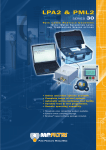
ICM-ETHi
Inline Contamination Monitor
Ethernet Interface
User Guide
www.mpfiltri.co.uk
200.139-EN
1 Introduction
The ICM-ETHi provides a convenient solution for connecting the ICM to an ethernet network. It plugs in directly to the ICM using a pre-wired connector. It can
be used with Lantronix software for network configuration.
The following functions are provided:
•
Ethernet to RS485 adaptor using Lantronix drivers.
•
Pre-wired ICM connector on 3m flying lead.
•
•
•
DC input socket for ICM power.
ICM signals brought out to user-accessible terminal block. This allows external
alarms, PLCs or a start button to be easily connected.
LED Indicators indicating Transmit (Tx) and Receive (Rx) data.
Figure 1
2
Introduction
2 Installation
An overview is given here for when the customer will be using our LPA-View software. This involves the following steps:
1 Connection
•
•
•
•
•
•
•
Connect ICM-ETHi to the ICM.
Plug the ICM-ETHi cable into the ICM.
Connect DC power supply, either using the DC connector provided or via the
internal terminal block.
Connect network cable between ICM-ETHi and customer network switch.
Install the Device Installer software from the Software CD or from the following
web address: http://ltxfaq.custhelp.com/app/answers/detail/a_id/644
Navigate to the Device Installer via Program menu - Follow menu instructions.
Identify and record the LAN address used by the device, e.g. 81.187.19.55
•
Access the Internet explorer (enter the LAN address in the navigation bar, Press
enter)
•
Access the ’’Serial Settings’’ tab and configure with the following changes from
the default (can ’’reset to default settings’’ first):
Protocol
RS485-2wire
Flow Control
None
Baud Rate
115200
Installation
3
Data Bits
8
Parity
Even
•
•
•
•
•
•
•
•
•
Stop Bits
1
Scroll Down to the bottom of the window and click ’Ok’
From the left hand options, click ’Apply Settings’
Install the Com Port redirector software from the Software CD or from the
following web address: http://ltxfaq.custhelp.com/app/answers/detail/a_id/928
Navigate to the CPR Manager via Program menu and Open
Add a new Com Port/ Add and Remove
Select (tick) an unused Com Port, e.g. Com 3 and click ’Ok’
Configure the Com Port being used - double click on COM port
Host (use value recorded earlier e.g.81.187.19.55) TCP Port 10001
Press the Save button - menu bar save settings
Please Note: the following message may appear:
Figure 1
4
Installation
•
•
Click Continue Anyway on all warnings
Access e.g. Com 3 test tab, click ’Open’ to prove connection to the Ethernet
adapter
•
Click ’Close’ and shut down CPR manager and Device installer
•
Install LPA-View as per the user guide.
•
Choose relevant Com port and click ’Ok’
•
The new COM port (e.g.COM 3) will now be available in LPA-View
•
Open LPA-View, open remote control (7th button from left on toolbar)
Installation
5
3 Lantronix Software Installation
We supply a version of the software on CD, or the latest version from the Lantronix
web site can be used.
Run the CPR installer. This is a file with a name like ``setup_cpr_x86x64cd_4.3.0.0’’.
Accept the security warning and license.
Figure 1
The ``CPR Installer’’
The software requires the Microsoft .NET Framework. If you do not have this
already, the installer will first install it for you. You will then need to restart the
computer and run the installer again to install the actual CPR program. Follow the
installation wizard accepting the defaults. You will need to accept another security
warning in order to install the Com Port driver software.
6
Lantronix Software Installation
4 Configuration
IP Address
In order to communicate on the network the ICM-ETHi requires an IP address. If
you have a DHCP server on the network, this will happen automatically. Otherwise
it is possible to assign one manually using the Lantronix Device Installer program
(a separate free program available from the Lantronix web site).
Creating the Virtual Com Port
Connect up the ICM-ETHi as described above and apply power. When the unit is
connected correctly you should see a continuous green LED to the left of the RJ45
socket after it has obtained an IP address.
Run the CPR program. Once started, press the Search button to search the network
for ICM-ETHi devices. Any such are displayed on the bottom line as in the example
below (with an appropriate IP address for your network).
Figure 1
Searching the Network
Once the device is found, a COM port can be created to enable it to be accessed
from LPA-View. Click the Add/Remove button to display the Com Ports dialogue
(Figure 2).
Configuration
7
Figure 2
Com Ports dialogue
Click on the desired Com port number (any can be used that do not conflict with
existing allocations). Press OK to close the dialogue. The new Com port will be
shown in the left hand pane, with the settings in red in the right hand pane.
As a shortcut, the settings can be filled in automatically. Click on the (New) Com
port shown on the left hand pane in Figure 3. Then double-click the found device
shown in the Device List at the bottom of the dialogue. Press the Save button to
save the configuration.
Configuration Test
Network communications can be tested using the Tests tab as in Figure 4.
Press the Open button. If successful, the dialogue will show ``Com Status: Open’’.
Press Close afterwards otherwise the Com port will not be available to LPA-View.
After this configuration, the new ``COM’’ port will be available to the LPA-View
Test Analysis Software. Proceed to connect to the ICM as detailed in the main ICM
manual.
8
Configuration
Figure 3
Com Port Settings
Figure 4
Testing
Configuration
9
5 Wiring Options
The unit can be used as-is for simple PC control of an ICM.
However all the ICM signals are made available at a terminal strip within the interface, so that these can be connected to a customers equipment. These include
a start signal and the two alarm outputs. Also included are the DC power input,
customers may prefer to permanently connect an existing supply here rather than
plugging in the provided DC adaptor. The RS485 signals (Data+, Data-) are also
present - these may be connected to an existing Modbus network.
To access the terminal strip, remove the four screws holding on the right hand
end-plate (the one with the ICM cable). The end-plate can then be detached and the
top plate slid off. An additional cable gland (supplied) can be fitted in the spare position on the end-plate and used for customer wires. Some example arrangements
are shown here, there is more information in the main ICM manual.
Figure 1
Pre-wired ICM Cable
Figure 1 shows the standard cable wiring. This is how the standard ICM-ETHi unit
is delivered.
10
Wiring Options
Figure 2
External Start
Figure 2 shows how to connect an external start button (or PLC output relay).
Figure 3
External Indicators
Figure 3 shows how to connect external indicator lamps (in case the built-in LED
is not sufficient). These could also be PLC inputs.
Figure 4
Wiring Options
External Power Supply
11
Figure 4 shows how to connect an external power supply. This arrangement may be
preferred for permanent installations over the removable ``plug-top’’ power supply
that comes with the unit.
Figure 5
Control Cable Extension
The standard cable is 3m in length. Wiring over longer distances should be done
using twisted pair cabling (assuming the serial communications signals are being
used). Figure 5 shows an example.
12
Wiring Options
Produced by MP Filtri UK
Revision 0.4
As a policy of continual improvement, MP Filtri UK reserve the right to alter specifications
without prior notice.
Except as permitted by such licence, no part of this publication may be reproduced, stored in
retrieval system or transmitted, in any form or any means, electronic, mechanical, recording, or
otherwise, without prior written permission of MP Filtri UK.
MP FILTRI UK Limited,
Bourton Industrial Park,
Bourton-on-the-Water,
GL54 2HQ, U.K.
Tel: +44.1451-822522
Fax: +44.1451-822282
Email: [email protected]
Website: www.mpfiltri.co.uk
www.mpfiltri.co.uk
ITALY - HEADQUARTERS
MP FILTRI S.p.A.
Tel: +39.02/95703.1
Fax: +39.02/95741497-95740188
Email: [email protected]
Website: www.mpfiltri.com
FRANCE
MP FILTRI FRANCE
Tel: +33.1.40-86-47-00
Fax: +33.1-40-86-47-09
Email: [email protected]
Website: www.mpfiltri.com
CANADA
MP FILTRI CANADA INC.
Tel: +1.905-303-1369
Fax: +1.905-303-7256
Email: [email protected]
Website: www.mpfiltricanada.com
INDIA
MP FILTRI INDIA
Tel: +91 9945599899
Email: [email protected]
Website: www.mpfiltri.com
CHINA
MP FILTRI (Shanghai) Co Ltd
Tel: +86.21-58919916
Fax: + 86.21-58919667
Email: [email protected]
Website: www.mpfiltrichina.com
GERMANY
MP FILTRI D GmbH
Tel: +49.6894-95652-0
Fax: + 49.6894-95652-20
Email: [email protected]
Website: www.mpfiltri.de
RUSSIAN FEDERATION
MP FILTRI RUSSIA INC
Phone mobile: +7.095-502-5411
Fax: +7.095-205-9410
Email: [email protected]
Website: www.mpfiltri.ru
USA
MP FILTRI USA Inc.
Tel: +1.215-529-1300
Fax: +1.215-529-1902
Email: [email protected]
Website: www.mpfiltriusa.com
UAE
MP FILTRI UEA
Tel: +91 9945599899
Email: [email protected]
Website: www.mpfiltri.com