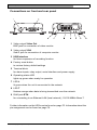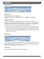
1
VIP XD – Network video server
Copyright
This user guide is the intellectual property of Bosch Security Systems and is
protected by copyright. All rights reserved. No part of this document may be
reproduced or transmitted for any purpose, by whatever means, electronic or
mechanical, without the express written permission of Bosch Security Systems.
Release: May 2005 (Software version 1.0)
© Copyright 2005 Bosch Security Systems
Note
This user guide has been compiled with great care and the information it contains
has been thoroughly verified. The text was complete and correct at the time of
printing. The ongoing development of the products may mean that the content of
the user guide can change without notice. Bosch Security Systems accepts no
liability for damage resulting directly or indirectly from faults, incompleteness or
discrepancies between the user guide and the product described.
Trademarks
All hardware and software product names used in this document are likely to be
registered trademarks and must be treated accordingly.
VIP XD | Installation and User Guide
Contents
EN | 3
0
Chapter 1 Preface
Conventions . . . . . . . . . . . . . . . . . . . . . . . . . . . . . . . . . . . . . . . . . 5
Intended use. . . . . . . . . . . . . . . . . . . . . . . . . . . . . . . . . . . . . . . . . 6
EU Directives . . . . . . . . . . . . . . . . . . . . . . . . . . . . . . . . . . . . . . . . 6
Rating plate . . . . . . . . . . . . . . . . . . . . . . . . . . . . . . . . . . . . . . . . . 6
Chapter 2 Safety information
Electric shock hazard . . . . . . . . . . . . . . . . . . . . . . . . . . . . . . . . . . 7
Installation and operation . . . . . . . . . . . . . . . . . . . . . . . . . . . . . . . 8
Maintenance and repair . . . . . . . . . . . . . . . . . . . . . . . . . . . . . . . . 8
Chapter 3 Product description
Components supplied. . . . . . . . . . . . . . . . . . . . . . . . . . . . . . . . . . 9
System requirements for setup . . . . . . . . . . . . . . . . . . . . . . . . . . 9
Configuration requirements . . . . . . . . . . . . . . . . . . . . . . . . . . . . 10
Operational requirements. . . . . . . . . . . . . . . . . . . . . . . . . . . . . . 10
Overview of functions . . . . . . . . . . . . . . . . . . . . . . . . . . . . . . . . . 11
Connections on front and rear panel . . . . . . . . . . . . . . . . . . . . . 13
Chapter 4 Installation
Connections . . . . . . . . . . . . . . . . . . . . . . . . . . . . . . . . . . . . . . . . 16
Turning on/off . . . . . . . . . . . . . . . . . . . . . . . . . . . . . . . . . . . . . . . 18
Setup using a terminal program . . . . . . . . . . . . . . . . . . . . . . . . . 19
Chapter 5 Configuration using a Web Browser
Connecting . . . . . . . . . . . . . . . . . . . . . . . . . . . . . . . . . . . . . . . . . 23
Choosing the configuration mode. . . . . . . . . . . . . . . . . . . . . . . . 25
Unit overview . . . . . . . . . . . . . . . . . . . . . . . . . . . . . . . . . . . . . . . 26
Configuration menu . . . . . . . . . . . . . . . . . . . . . . . . . . . . . . . . . . 43
Function test. . . . . . . . . . . . . . . . . . . . . . . . . . . . . . . . . . . . . . . . 60
Chapter 6 Operation using a Web Browser
Establishing the connection . . . . . . . . . . . . . . . . . . . . . . . . . . . . 61
The CONNECTIONS page. . . . . . . . . . . . . . . . . . . . . . . . . . . . . 64
Connections between the transmitter and receiver . . . . . . . . . . 65
Bosch Security Systems | 2005-05 | V1.0
EN | 4
Installation and User Guide | VIP XD
Chapter 7 Operation with a terminal program
Connecting with a terminal program. . . . . . . . . . . . . . . . . . . . . . 67
Closing the connection with a terminal program . . . . . . . . . . . . 67
Additional parameters . . . . . . . . . . . . . . . . . . . . . . . . . . . . . . . . 67
Chapter 8 Operation with management software
Managing and operating transmitters and receivers . . . . . . . . . 69
Chapter 9 Maintenance and upgrades
Testing the network connection . . . . . . . . . . . . . . . . . . . . . . . . . 71
Device reset . . . . . . . . . . . . . . . . . . . . . . . . . . . . . . . . . . . . . . . . 71
Repairs . . . . . . . . . . . . . . . . . . . . . . . . . . . . . . . . . . . . . . . . . . . . 72
Transfer and disposal. . . . . . . . . . . . . . . . . . . . . . . . . . . . . . . . . 72
Chapter10 Appendix
Troubleshooting . . . . . . . . . . . . . . . . . . . . . . . . . . . . . . . . . . . . . 73
LEDs. . . . . . . . . . . . . . . . . . . . . . . . . . . . . . . . . . . . . . . . . . . . . . 75
Terminal block . . . . . . . . . . . . . . . . . . . . . . . . . . . . . . . . . . . . . . 76
Glossary . . . . . . . . . . . . . . . . . . . . . . . . . . . . . . . . . . . . . . . . . . . 77
Specifications . . . . . . . . . . . . . . . . . . . . . . . . . . . . . . . . . . . . . . . 79
Chapter11 Index
Bosch Security Systems | 2005-05 | V1.0
VIP XD | Installation and User Guide
Preface
EN | 5
1
This user guide is intended for persons responsible for the installation and
operation of the VIP XD. International, national and any regional regulations
regarding electronics must be followed at all times. Relevant knowledge of
network technology is required. The user guide describes the installation and
operation of the unit.
Conventions
In this user guide, the following symbols and notation are used to draw attention
to special situations:
Warning!
This symbol indicates that failure to follow the safety instructions described
may endanger persons and cause damage to the unit or other equipment.
It is associated with immediate, direct hazards.
Note
This symbol indicates tips and information for easier, more convenient use
of the unit.
Bosch Security Systems | 2005-05 | V1.0
Preface
EN | 6
Installation and User Guide | VIP XD
Intended use
The VIP XD network video server receives video and control signals over data
networks (Ethernet LAN, Internet). It is designed for use in CCTV systems. By
incorporating external alarm sensors, various functions can be triggered
automatically. Other applications are not permitted.
In the event of questions concerning the use of the unit, which are not answered
in this user guide, please contact your sales partner or:
Bosch Sicherheitssyteme GmbH
Robert-Koch-Straße 100
85521 Ottobrunn
Germany
www.bosch-sicherheitssysteme.de
EU Directives
The VIP XD network video server complies with the requirements of EU
Directives 89/336 (Electromagnetic Compatibility) and 73/23, amended by 93/68
(Low Voltage Directive).
Rating plate
For exact identification, the model name and serial number are inscribed on the
rating plate on the bottom of the housing. Please note this information if
necessary before installation so it will be available in case of questions or for
spare parts orders.
Preface
Bosch Security Systems | 2005-05 | V1.0
VIP XD | Installation and User Guide
Safety information
EN | 7
2
Electric shock hazard
] Never attempt to connect the unit to any power network other than the type
for which it was intended.
] Use only the power supply provided.
] Never open the housing!
] If a fault occurs, disconnect the power supply unit from the mains supply and
from all other devices.
] Install the power supply and the unit only in dry, weather-protected areas.
] If safe operation of the unit cannot be ensured, remove it from service and
secure it to prevent unauthorized start-up. Safe operation is no longer
possible in the following cases:
– if there is visible damage to the unit or power cables,
– if the unit no longer works properly,
– if the unit has been exposed to rain or moisture,
– if foreign matter has infiltrated the unit,
– after long storage under adverse conditions or
– after exposure to extraordinary transport stress.
In such cases, have the unit checked by Bosch Security Systems.
Bosch Security Systems | 2005-05 | V1.0
Safety information
EN | 8
Installation and User Guide | VIP XD
Installation and operation
] The relevant electrical regulations and guidelines must be complied with at all
times during installation.
] Relevant knowledge of network technology is required to install the unit.
] Before installing or operating the unit, make sure you have read and
understood the documentation for the other equipment connected, such as
cameras. This contains important safety instructions and information about
permitted uses.
] Perform only the installation and operating steps described in this manual.
Actions beyond these may lead to personal injury, damage to property or
damage to the equipment.
Maintenance and repair
] Never open the casing of the VIP XD. The unit does not contain any user
serviceable parts.
] Never open the housing of the power supply unit. The power supply unit does
not contain any user serviceable parts.
] Ensure that all maintenance or repair work is performed only by qualified
personnel (electrical engineering or network technology specialists).
Safety information
Bosch Security Systems | 2005-05 | V1.0
VIP XD | Installation and User Guide
Product description
EN | 9
3
Components supplied
] VIP XD network video server
] Power supply unit with four primary adapters
] Configuration cable
] Quick start guide in English/German
] Product CD with the following content:
– Quick start guide in English/German
– User guide in English/German
– System requirements data sheet
– MPEG ActiveX control
– MPEG viewer
– DirectX control
– Microsoft Internet Explorer
– Microsoft Virtual Machine
– Adobe Acrobat Reader
Note
Check that the delivery is complete and in perfect condition. Arrange for
the unit to be checked by Bosch Security Systems if you find any damage.
System requirements for setup
] Computer with Windows 2000/XP operating system, access to network and
Microsoft Internet Explorer (version 6.0 or later)
or
] Computer with Windows 2000/XP operating system, an available serial port
and terminal software
Bosch Security Systems | 2005-05 | V1.0
Product description
EN | 10
Installation and User Guide | VIP XD
Configuration requirements
] Computer with Windows 2000/XP operating system, network access and
Microsoft Internet Explorer web browser (version 6.0 or later)
or
] Computer with Windows 2000/XP operating system, network access and
management software, for example VIDOS
Note
You should also take note of the information in the System requirements
document on the product CD supplied.
Make sure the graphics card is set to 16 or 32 bit color depth and that
Microsoft Virtual Machine is installed on your PC. If necessary, the
required software and controls can be installed from the product CD
provided (see Components supplied, page 9).
Operational requirements
] Computer with Windows 2000/XP operating system, network access and
Microsoft Internet Explorer web browser (version 6.0 or later)
or
] Computer with Windows 2000/XP operating system, network access and
management software, for example VIDOS
Note
You should also take note of the information in the System requirements
document on the product CD supplied.
Make sure the graphics card for reception on the computer monitor is set
to 16 or 32 bit color depth and that Microsoft Virtual Machine is installed
and activated on the PC. If necessary, the required software and controls
can be installed from the product CD provided (see Components
supplied, page 9).
Product description
Bosch Security Systems | 2005-05 | V1.0
VIP XD | Installation and User Guide
EN | 11
Overview of functions
Network video receiver with Quad View
The VIP XD is an ultra-compact network video receiver for simultaneous
reception of up to four video streams. It is primarily designed for decoding video
data after transfer over an IP network and for transmission of control data. When
connected to a monitor and used in conjunction with compatible MPEG-4 video
servers, the VIP XD is ideally suited for making previously analog CCTV
systems IP-compatible.
About the size and shape of a cigarette packet, it can be integrated into small
housings without difficulty if necessary. The use of existing networks means that
integration with CCTV systems or local networks can be achieved quickly and
easily.
Two units, for example a VIP X1 / VIP X2 as the transmitter and another VIP XD
as the receiver, can form a stand-alone system for data transfer without a PC.
Video images from a single transmitter can be simultaneously received on
several receivers. A VIP XD receiver can simultaneously receive up to four video
streams from one or more compatible transmitters.
Transmitter
MPEG-4 compatible hardware decoders, for example VIP X 1, VIP X 2 or
VideoJet 8008 can be used as transmitters. Computers with the VIDOS software
installed are suitable for connecting the desired transmitters to the relevant
receiver.
Multicast
In suitably configured networks, the multicast function enables simultaneous,
real time transmission to multiple receivers. The prerequisite for this is that the
UDP and IGMP V2 protocols are implemented on the network.
Configuration
The VIP XD can be configured using a browser on the local network (Intranet)
or from the Internet.
Similarly, firmware updates and rapid loading of device configurations are also
possible.
Bosch Security Systems | 2005-05 | V1.0
Product description
EN | 12
Installation and User Guide | VIP XD
Summary
The VIP XD provides the following main functions:
] Video and data reception over IP data networks
] Quad View function with simultaneous decoding of four video streams
] BNC video output FBAS (PAL/NTSC) for connection of analog monitor and
Sub-D video interface (VGA/SVGA) for connection of computer monitor
] Video decoding using MPEG-4 with expansions
] Integrated Ethernet interface (10/100 Base-T)
] Transparent bi-directional data channel using a serial interface
RS232/RS422/RS485
] Remote control of all built-in functions via TCP/IP
] Password protection to prevent unauthorized connection or configuration
changes
] Four relay inputs for external sensors (such as door contacts)
] Event-driven, automatic connection (for example at switch-on and for alarms)
] Fast and convenient configuration using integrated web server and browser
] Firmware update using flash memory
] Convenient upload of configuration data
Product description
Bosch Security Systems | 2005-05 | V1.0
VIP XD | Installation and User Guide
EN | 13
Connections on front and rear panel
1 Video output Video Out
BNC jack for connection of video monitor
2 Video output VGA
Sub-D jack for connection of computer monitor
3 USB interface
for future expansion of recording function
4 Factory reset button
to restore factory default settings
5 Terminal block
for alarm inputs, relay output, serial interface and power supply
6 Operating status LED
lights up green when ready for operation
7 LED L
lit green when the unit is connected to the network
8 LED T
flashes orange when data is being transmitted over the network
9 RJ45 jack ETH
for connecting to an Ethernet LAN (local network), 10/100 MBit/s Base-T
Further information on the LEDs can be found on page 75. Information about the
pin assignment can be found on page 76.
Bosch Security Systems | 2005-05 | V1.0
Product description
EN | 14
Product description
Installation and User Guide | VIP XD
Bosch Security Systems | 2005-05 | V1.0
VIP XD | Installation and User Guide
Installation
EN | 15
4
Thanks to its ultra-compact dimensions, the VIP XD is particularly well suited for
installation in housings or consoles where space is at a premium.
Warning!
The unit is intended for use indoors or in protected spaces. Select a
suitable location for installation where the unit will not be subjected to
conditions of extreme temperature or humidity. The ambient temperature
must be between 0 and +50 °C, and the relative humidity may not exceed
80%.
The unit generates heat during operation. Ensure that there is adequate
ventilation and also that there is enough clearance between the unit and
heat-sensitive objects or equipment.
Please ensure the following conditions for installation:
] Do not install the unit close to heaters or other heat sources. Avoid locations
subject to direct sunlight.
] Allow sufficient space for running cables.
] Ensure that the unit has adequate ventilation.
] Use only the cables supplied for connections or appropriate cables resistant
to electromagnetic interference.
] Position and run all cables so that they are protected from damage, and
provide strain relief where needed.
] Avoid impacts, blows and severe vibrations as these can lead to irreparable
damage to the unit.
Bosch Security Systems | 2005-05 | V1.0
Installation
EN | 16
Installation and User Guide | VIP XD
Connections
Monitors
If required, you can connect an analog video monitor (PAL/NTSC) or a VGAcompatible computer monitor.
– Connect an analog video monitor to the BNC jack Video Out with a video
cable (75 Ohm, BNC connector)
or
– Connect a VGA compatible computer monitor to the Sub-D jack VGA with a
video cable (VGA, 15-pin Sub-D connector).
Data interface
The bi-directional data interface is used to transmit control data for a unit
connected to the VIP XD, such as a control panel for dome cameras.
The interface supports the RS232, RS422 and RS485 transmission standards.
The serial interface is made up of four terminals of the ST500 jack (for pin
assignment see page 76).
The manufacturers of the relevant equipment can provide specific information
on installation and operation.
Warning!
Refer to the associated documentation when installing and operating the
control unit. This contains important safety instructions and information
about permitted uses.
Note
A video connection is necessary to transmit transparent data.
Network
You can connect the VIP XD to a 10/100 Base-T network. Use a standard UTP
Category 5 cable with RJ45 connectors for this.
– Connect the unit to the network using the ETH jack.
Installation
Bosch Security Systems | 2005-05 | V1.0
VIP XD | Installation and User Guide
EN | 17
Alarm inputs
The VIP XD has four alarm inputs on the orange terminal block (for pin
assignment, see page 76). The alarm inputs are used to connect to external
alarm devices, such as door contacts or sensors. With the appropriate
configuration, an alarm sensor can, for example, trigger an automatic
connection between the VIP XD and a particular transmitter.
A voltage free contact or switch can be used as an actuator.
Note
If possible, use a bounce-free contact system as the actuator.
– Connect the lines to the appropriate terminals on the orange terminal block
(IN1 to IN4) and check that the connection is secure.
Relay output
The VIP XD has a relay output for switching external devices, such as lights or
audible alarms. This relay output can be activated manually during a connection
session with the VIP XD. Moreover, the output can be configured to activate
audible alarms or other devices as a response to an alarm signal. The relay
output is also located on the orange terminal block (for pin assignment see
page 76).
Warning!
The maximum rating of the relay contact is 30 V and 2 A.
– Connect the lines to the appropriate terminals (R) on the orange terminal
block and check that the connection is secure.
Bosch Security Systems | 2005-05 | V1.0
Installation
EN | 18
Installation and User Guide | VIP XD
Turning on/off
Mains connection
The VIP XD includes a mains power supply with four primary adapters and
terminal block. The VIP XD does not have a power switch. The unit is ready for
operation as soon as it is connected to the power supply.
Warning!
To operate the VIP XD, use exclusively the power supply unit supplied
with the correct primary adapter for your mains socket. Use suitable
equipment where necessary to ensure that the mains supply is free of
interference such as voltage surges, spikes or voltage drops.
Warning!
Only connect the VIP XD to the mains supply once everything else has
been connected.
– Connect the cable to the power supply unit and the orange terminal block of
the VIP XD.
– Ensure that the correct primary adapter is attached to the power supply unit
and an appropriate mains socket is available.
– Plug the power supply unit into a grounded mains socket. The unit is ready
for operation as soon as the "operating status" LED stops flashing red during
start-up and is lit green.
If the network connection is in order, the green L LED is also lit. The flashing
orange T LED indicates data traffic on the network.
Installation
Bosch Security Systems | 2005-05 | V1.0
VIP XD | Installation and User Guide
EN | 19
Setup using a terminal program
Data terminal
You can connect a data terminal to the VIP XD for setup and local control. The
data terminal consists of a computer with terminal software. You can use the
configuration cable supplied for the connection (for assignment on the orange
terminal block, see page 76).
HyperTerminal, a communications accessory included with Microsoft Windows,
can be used as the terminal program.
Note
Information on installing and using HyperTerminal can be found in the user
guides or online help for MS Windows.
– Before using the terminal program, disconnect the VIP XD from the data
network and disconnect the power supply unit from the mains socket.
– Connect the open lines of the configuration cable to the terminal block that is
already connected to the power supply unit. The assignment can be seen
from the labels on the configuration cable and the markings on the terminal
block.
– Connect the terminal block to the orange socket on the unit.
– Connect the VIP XD configuration cable to a free serial port on your
computer.
– Ensure that the correct primary adapter is fitted and connect the power supply
unit to an appropriate mains socket.
Configuring the terminal
To establish communication between the terminal program and the VIP XD, the
transmission parameters must be correctly defined. The following values should
be set in the terminal program:
] 19,200 Bit/s
] 8 data bits
] No parity check
] 1 stop bit
] No protocol
Bosch Security Systems | 2005-05 | V1.0
Installation
EN | 20
Installation and User Guide | VIP XD
Command entry
After the connection has been established, you must log on to the VIP XD. You
can then access the main menu. You can call up additional submenus and
functions using the on-screen commands.
– If necessary, turn off the local echo so that entered values are not repeated
on the display.
– Enter only one command at a time.
– After entering a value (such as an IP address), re-check the entry before
pressing the ENTER key to transfer the values to the VIP XD.
Assigning an IP address
To operate the VIP XD in your network, a valid IP address for the network must
be assigned.
The following default address has been pre-set at the factory: 192.168.0.1
– Start up a terminal program such as HyperTerminal.
– Enter the user name service. The main menu will be displayed.
– Enter the command 1 to open the IP menu.
– Enter 1 again. The current IP address will be displayed, and you will be
requested to enter a new IP address.
Installation
Bosch Security Systems | 2005-05 | V1.0
VIP XD | Installation and User Guide
EN | 21
– Enter the desired IP address and press Enter. The new IP address will be
shown.
– Use the commands displayed for any additional settings required.
Note
The new IP address and a new subnet mask or gateway address will only
be valid after restarting.
Restart
Briefly disconnect the power supply to the VIP XD (disconnect power supply unit
and re-connect after a few seconds).
Additional parameters
Using the terminal program, you can check other basic parameters and modify
them where necessary. Use the on-screen commands displayed in the various
submenus to do this.
Bosch Security Systems | 2005-05 | V1.0
Installation
EN | 22
Installation
Installation and User Guide | VIP XD
Bosch Security Systems | 2005-05 | V1.0
EN | 23
VIP XD | Installation and User Guide
Configuration using a Web Browser
5
Connecting
The integrated HTTP server allows the unit to be configured over the network
with a Web browser. This option is significantly more comprehensive and
convenient than configuration using a terminal program.
Note
Make sure the graphics card is set to 16 or 32 bit colour depth and that
Microsoft Virtual Machine is installed on your PC. If necessary, the
required software and controls can be installed from the product CD
provided (see Components supplied, page 9).
Instructions for using the Web browser can be found in its online help.
System requirements
] Microsoft Internet Explorer (version 6.0 or higher)
] Monitor resolution 1024 × 768 pixels
] Network access (Intranet or Internet)
Note
You should also take note of the information in the System requirements
document on the product CD supplied.
Install MPEG ActiveX
Note
In order to be able to play back live video images, an appropriate MPEG
ActiveX must be installed on the computer. If necessary, the required
software and controls can be installed from the product CD provided (see
Components supplied, page 9).
– Insert the CD into the CD-ROM drive of the computer. If the CD does not start
automatically, open the root directory of the CD in Windows Explorer and
double click MPEGAx.exe.
– Follow the on-screen instructions.
Bosch Security Systems | 2005-05 | V1.0
Configuration using a Web Browser
EN | 24
Installation and User Guide | VIP XD
Establishing the connection
The VIP XD must be assigned a valid IP address to operate on your network.
The following default address has been pre-set at the factory: 192.168.0.1
– Start the Web browser.
– Enter the IP address of the VIP XD as the URL. The connection will be
established and, after a short time, you will see the SETTINGS page
containing the unit overview and the configuration menu.
If the connection is not established, the maximum number of possible
connections may already have been reached. The maximum number of
connections depends on the device and network configuration.
Password protection in VIP XD
If the VIP XD is password-protected against unauthorized access, a
corresponding message and a prompt to enter the password will appear when
you attempt to access protected areas.
Configuration using a Web Browser
Bosch Security Systems | 2005-05 | V1.0
EN | 25
VIP XD | Installation and User Guide
Note
A VIP XD offers you the option of limiting access across various
authorization levels (see pages 35 and 44).
– Enter the user name and associated password in the corresponding text
fields.
– Click OK. If the password is correct, the desired page is displayed.
Choosing the configuration mode
There are two options for configuring the VIP XD or checking the current setup:
] the unit overview or
] the configuration menu.
All settings are stored in the VIP XD memory, and they are preserved even if the
power is interrupted.
Unit overview
The unit overview shows the most important parameters summarized into six
groups.
This allows you to change the default settings with just a few clicks and entries
(see Unit overview, page 26).
Configuration menu
The configuration menu is recommended for expert users or system
administrators. All unit parameters can be accessed in this mode.
Changes that influence the fundamental functioning of the unit (for example
firmware updates) can only be made using the configuration menu (see
Configuration menu, page 43).
Bosch Security Systems | 2005-05 | V1.0
Configuration using a Web Browser
EN | 26
Installation and User Guide | VIP XD
Unit overview
The unit overview gives you a graphical overview of the individual areas of the
configuration. The individual configuration parameters are grouped and
displayed in separate windows. You can access the individual areas directly.
– Click one of the group graphics. A new page is opened.
– Click in the text fields to enter values or use the other controls available, such
as buttons, check boxes or list fields.
– Click on the SETTINGS link at the top of the window to close the window
without saving the changes made.
Making changes
After making changes in a window, click the Set button to send the new settings
to the unit and save them there.
Warning!
Save the changes made in each window by clicking Set. Clicking the Set
button always saves only the settings in the current window.
A description is given below of the individual windows that can be accessed
using the graphical symbols in the overview.
Configuration using a Web Browser
Bosch Security Systems | 2005-05 | V1.0
VIP XD | Installation and User Guide
EN | 27
Decoder settings
On this page, you can set the various options for the display of video images on
an analog monitor or a VGA monitor. Several presets are available for
configuration of the VGA video output signal.
MPEG decoder
Monitor name:
The monitor name is used for easy identification of the monitor location when
using VIDOS, the software for management of video surveillance systems.
Enter a unique, unambiguous name here.
Video output standard:
Warning!
Be sure to choose the correct video standard to avoid damaging the
monitor. Selecting a VGA setting with values outside the technical
specification of the monitor can result in severe damage to the monitor.
Refer to the technical documentation for the monitor you are using.
You can adapt the video output signal to the monitor you are using. As well as
the PAL and NTSC options for analog video monitors, 8 pre-configured settings
for VGA monitors are also available.
The pre-configured settings each give priority to different factors (resolution,
margin settings, refresh rate). Details of the settings can be seen on the MPEG
decoder configuration page in the VGA Settings field (accessed using the
Monitor icon in the unit overview).
Bosch Security Systems | 2005-05 | V1.0
Configuration using a Web Browser
EN | 28
Installation and User Guide | VIP XD
– Test different pre-configured settings from the list to obtain an optimum
monitor image.
– After selecting a setting, click on the Set button so that the setting takes effect
at the video output.
Note
If necessary, the presets for the VGA output signal can be viewed on the
MPEG decoder page (Monitor icon in the unit overview) and adapted to
individual requirements (see page 29).
Window layout:
You can specify the default image configuration for the monitor. This can be also
be selected at any time during operation on the CONNECTIONS page.
VGA monitor screen size:
Enter the aspect ratio of the screen here (for example 4 × 3) or the physical size
of the screen in millimeters. This information allows the unit to accurately scale
the video image for distortion-free display.
Configuration using a Web Browser
Bosch Security Systems | 2005-05 | V1.0
VIP XD | Installation and User Guide
EN | 29
Monitor settings
On this page, you can set the various options for the display of video images on
an analog monitor or a VGA monitor. Several presets are available for
configuration of the VGA video output signal. These presets can be adapted to
individual requirements if necessary.
MPEG decoder
Monitor name:
The monitor name is used for easy identification of the monitor location when
using VIDOS, the software for management of video surveillance systems.
Enter a unique, unambiguous name here.
Video output standard:
Warning!
Be sure to choose the correct video standard to avoid damaging the
monitor. Selecting a VGA setting with values outside the technical
specification of the monitor can result in severe damage to the monitor.
Refer to the technical documentation for the monitor you are using.
You can adapt the video output signal to the monitor you are using. As well as
the PAL and NTSC options for analog video monitors, eight pre-configured
settings for VGA monitors are also available.
The pre-configured settings each give priority to different factors (resolution,
border settings, image refresh rate).
Bosch Security Systems | 2005-05 | V1.0
Configuration using a Web Browser
EN | 30
Installation and User Guide | VIP XD
Details of the settings can be seen in the VGA Settings field. There, you can
also adapt the options to individual requirements if necessary.
– Test different pre-configured settings from the list to obtain an optimum
monitor image.
– After selecting a setting, click on the Set button so that the setting takes effect
at the video output.
Window layout:
You can specify the default image configuration for the monitor. This can be also
be selected at any time during operation on the CONNECTIONS page.
VGA monitor screen size:
Enter the aspect ratio of the screen here (for example 4 × 3) or the physical size
of the screen in millimeters. This information allows the unit to accurately scale
the video image for distortion-free display.
VGA Settings
The pre-configured settings are saved as Profile 1 to Profile 8. You can change
the different parameter values within a profile. You can switch between profiles
by clicking the associated tabs.
Configuration using a Web Browser
Bosch Security Systems | 2005-05 | V1.0
EN | 31
VIP XD | Installation and User Guide
The pre-configured settings (profiles) cover all standard applications. Only
change the preset values if none of the profiles leads to satisfactory results.
Warning!
Setting values that lie outside the technical specification of the monitor can
result in severe damage to the monitor. Refer to the technical
documentation for the monitor you are using.
Note
All parameters combine to make up a profile. The parameters are partially
independent of one another.
After each change, click the Test button to see the effect of the change on
the connected monitor.
Resolution:
You can enter the desired screen resolution in pixels here. On digital flat screens
(LCD, TFT and others) the optimum resolution corresponds to the actual number
of pixels.
Note
By default, resolutions up to 800 × 600 pixels are supported.
Refresh rate:
Enter the desired refresh rate, based on the technical specification of the
monitor you are using. For fluid video playback, the setting 50Hz is used for PAL
sources and the 60 Hz setting for NTSC sources.
Note
For tube monitors, higher refresh rates may be useful for ergonomic
reasons. However, to prevent damage to monitors that do not support
these refresh rates, the exact monitor data must first be set using the
terminal program (see page 19).
Border top / bottom / left / right:
You can place a frame around the video image to make it easier to see. You can
set the width of all four borders individually. The color of the frame (gray tone)
can be specified in the Details window (see page 32).
Bosch Security Systems | 2005-05 | V1.0
Configuration using a Web Browser
EN | 32
Installation and User Guide | VIP XD
horiz. spacing / vert. spacing:
For four-way division of the screen, in addition to the outer frame you can also
define separating lines between the different images. You can set the width of
the horizontal and vertical separating lines individually. The color is identical to
the frame color.
Screen position
You can move the video image horizontally and vertically within the screen area.
In addition, you can adjust the width and height of the video image.
– Click on one of the four arrows in the large monitor graphic to move the video
image in the corresponding direction.
– Click on the plus or minus symbols next to the small monitor graphics to
change the size of the video image.
Note
If the horizontal and vertical scaling of the monitor image is changed, the
new values for Hor. scan rate: and Dot clock: are immediately displayed
in the fields above the monitor graphics for information. You cannot enter
or change these values directly in the fields.
Details
The Details window allows you to adapt the video output signal to specific
requirements in more detail. In addition, you can set the frame color for the
image border.
Horizontal sync. / Vertical synch.
Here, you can select the way in which the relevant synchronization pulse is to
be output.
Bordercolor
Here, you can set the desired gray tone for the outer frame and any separating
lines between the video images for four-way division of the screen.
– Click on the arrows or move the slider with the mouse button held down.
Sync. length / Retrace length / Sync. position
Here, you can adjust the settings for the synchronization signals to specific
requirements if necessary.
Configuration using a Web Browser
Bosch Security Systems | 2005-05 | V1.0
VIP XD | Installation and User Guide
EN | 33
Resetting changes
You can undo all changes to the profiles and reset each profile to its original
settings.
– Click on the Defaults button to reset the settings for the profile currently
displayed to their default values.
– If you want to discard changes to a profile that have not yet been explicitly
saved, click on the Discard button. You will see the last saved settings for
that profile.
Saving changes
When you have tested your settings on the connected monitor by clicking on the
Test button, you can save the new settings. Saving only applies to the profile
that is currently displayed.
– Click on the Save button to save the current profile with the values displayed.
Bosch Security Systems | 2005-05 | V1.0
Configuration using a Web Browser
EN | 34
Installation and User Guide | VIP XD
System settings
Various basic data for the VIP XD can be set or selected here.
Unit identification
Unit name:
The unit can be assigned a name to assist in identifying it. The name simplifies
the management of multiple units in large video surveillance systems, for
example using the VIDOS software.
Note
The unit name is used for remote identification of a unit, in the event of an
alarm for example. Enter a name that makes it as easy as possible to
identify the location unambiguously.
Unit ID:
Each VIP XD should be assigned a unique identifier that can be entered here as
an additional means of identification.
Password
A VIP XD is generally protected by a password to prevent unauthorized access
to the unit. You can use various authorization levels (User name:) to limit
access.
Configuration using a Web Browser
Bosch Security Systems | 2005-05 | V1.0
VIP XD | Installation and User Guide
EN | 35
Note
Proper password protection with a user password is only guaranteed if the
higher authorization level service is also protected by a password. The
passwords for the service authorization level should therefore always be
assigned first.
User name:
The VIP XD operates with two user names: service and user, which correspond
to different authorization levels.
The user name service represents the highest authorization level. After entering
the corresponding password, you can use it to access all the functions of the
VIP XD and change all configuration settings.
The user name user represents the middle authorization level. You can use it to
connect the unit to a transmitter in the network and to disconnect but not to
change the configuration.
Password:
You can define and change a separate password for each user name if you are
logged on as service or if the unit is not protected by a password.
Enter the password for the selected user name here.
Confirm password:
Re-enter the new password to rule out typing mistakes.
Note
The new password is then saved by clicking the Set button. You should
therefore click the Set button immediately after entering and confirming
the password, even if you also want to assign a password to another user
name.
Language
Website language:
Select the language for the user interface here.
Bosch Security Systems | 2005-05 | V1.0
Configuration using a Web Browser
EN | 36
Installation and User Guide | VIP XD
Date and time
Date format:
Choose the desired date format here
(Europe: DD.MM.YYYY; USA: MM.DD.YYYY; Japan: YYYY/MM/DD).
Unit date and time:
If there are a number of devices operating in your system or network, it is
important to synchronize their internal clocks. For example, it is only possible to
carry out correct identification and evaluation of recordings occurring at the
same time if all devices are operating on the same time.
– Enter the current date. Since the unit time is controlled by the internal clock,
it is not necessary to enter the day of the week. This is added automatically.
– Enter the current time or click Synchr. PC to apply the system time from your
computer to the VIP XD.
Version information
The hardware and firmware version numbers are for information only and cannot
be altered. Keep a record of these numbers in case technical assistance is
required.
Hardware version:
The hardware version number of the VIP XD is displayed.
Firmware version:
The firmware version number of the VIP XD is displayed.
Configuration using a Web Browser
Bosch Security Systems | 2005-05 | V1.0
EN | 37
VIP XD | Installation and User Guide
Alarm settings
Here, you can make the settings for the alarm sources and alarm connections.
Alarm sources
You can configure the alarm inputs on the VIP XD here.
Alarm input 1 … Alarm input 4:
Select the option On in order to activate the alarm via the corresponding external
alarm sensor. Otherwise, select Off.
Select Active high if the alarm is to be triggered by closing the contact. Select
Active low if the alarm is to be triggered by opening the contact.
Name:
For easier identification, you can enter a name for each alarm input.
Alarm connections
You can select the response of the VIP XD in case of an alarm. In case of an
alarm, the VIP XD can automatically establish a connection to a predefined IP
address (compatible MPEG-4 compatible video server). You can enter up to ten
Bosch Security Systems | 2005-05 | V1.0
Configuration using a Web Browser
EN | 38
Installation and User Guide | VIP XD
IP addresses which will be selected in order by the unit in case of an alarm until
a connection is established.
Connect on alarm:
Select On so that the VIP XD automatically establishes a connection to a predefined IP address in the event of an alarm.
With the setting Follows alarm 1, the VIP XD automatically establishes a
connection to a remote station and maintains it for as long as an alarm signal is
present at alarm input 1. This option can also be used to connect two units
(transmitter and receiver) via a switch connected to the VIP XD. In this case, no
computer is needed to establish the connection.
Number of destination IP address:
Here you assign the numbering for the IP addresses to be contacted in the event
of an alarm. The unit contacts the remote locations one after the other in the
numbered sequence until a connection has been established.
Destination IP address:
For each number, enter the corresponding IP address for the desired remote
location.
Destination password:
If the remote location is password protected, enter the password here.
Auto-connect:
Select the option On if an active connection should be re-established
automatically to one of the previously specified IP addresses after each restart,
after a connection breakdown or network failure.
Configuration using a Web Browser
Bosch Security Systems | 2005-05 | V1.0
EN | 39
VIP XD | Installation and User Guide
Network settings
Here, you can specify network addresses and configure multiple connections.
Network
The settings on this page are used to integrate the unit into an existing network.
Warning!
Changes to the IP address, subnet mask or gateway address are
transferred to the unit by clicking Set. However, they only take effect after
the unit is restarted.
– Click Set after entering a new IP address.
– To do this, enter the old IP address followed by /reset (for instance
192.168.0.80/reset) in the address bar of your web browser. The
VIP XD will be restarted, after which it can only be accessed at the new IP
address.
Unit IP address:
Enter the desired IP address for the VIP XD in this field. The IP address must be
valid for the network.
Subnet mask:
Enter the appropriate subnet mask for the set IP address here.
Bosch Security Systems | 2005-05 | V1.0
Configuration using a Web Browser
EN | 40
Installation and User Guide | VIP XD
Gateway IP address:
If you want the unit to establish a connection to a remote location in a different
subnet, enter the IP address of the gateway here. Otherwise, this field can
remain empty (0.0.0.0).
Video/audio transmission:
If the unit is used behind a firewall, TCP (Port 80) should be selected as the
transmission protocol. For use in a local network, choose UDP.
Warning!
Multicast operation is only possible with the UDP protocol. The TCP
protocol does not support multicast connections.
Note
The MTU value in UDP mode is 1514 bytes.
Ethernet link type:
If the VIP XD is connected to the network via a switch, both devices must have
the same preset network connection type. If necessary, ask your network
administrator what value the associated switch is set to.
The Auto setting automatically detects the network connection. If necessary,
you can specify the value 10 or 100 MBit/s for full or half-duplex mode (FD or
HD).
Warning!
Malfunctions can occur (for example image faults) if the capacity of the
network is not sufficient for transmission of the maximum data rate
generated by the transmitter.
Configuration using a Web Browser
Bosch Security Systems | 2005-05 | V1.0
EN | 41
VIP XD | Installation and User Guide
COM1 settings
You can configure the parameters of the serial interface to meet your
requirements.
Serial port function:
Select the desired serial port function from the list.
If you want to use the serial port to transmit transparent data, for example when
using a control panel, select Transparent. To operate the unit with a terminal,
choose Terminal.
Baud rate:
Select the value for the transmission rate in Bit/s.
Data bits:
The number of data bits per character cannot be changed.
Stop bits:
Select the number of stop bits per character.
Parity check:
Select the type of parity check.
Bosch Security Systems | 2005-05 | V1.0
Configuration using a Web Browser
EN | 42
Installation and User Guide | VIP XD
Interface mode:
Select the desired protocol for the serial interface.
Half-duplex mode:
Choose the setting appropriate for your application.
Configuration using a Web Browser
Bosch Security Systems | 2005-05 | V1.0
EN | 43
VIP XD | Installation and User Guide
Configuration menu
The configuration menu allows all parameters of the VIP XD to be configured.
You can view the current settings by opening one of the configuration pages.
The settings can be changed by entering new values or by selecting a
predefined value in a list field.
Navigation
You will see the configuration menu in addition to the unit overview after clicking
on the SETTINGS link.
– Click on one of the menu options on the left of the window. The associated
sub-menu is opened.
– Click one of the links in the sub-menu. The corresponding page will be
opened.
Making changes
Each configuration page shows the current settings. The settings can be
changed by entering new values or by selecting a predefined value in a list field.
Bosch Security Systems | 2005-05 | V1.0
Configuration using a Web Browser
EN | 44
Installation and User Guide | VIP XD
– After each change, click Set to save the change.
Warning!
Save each change with the associated Set button. Clicking Set always
saves only the settings in the particular field. Changes in any other fields
are ignored.
Unit identification
Unit name:
The unit can be assigned a name to assist in identifying it. The name simplifies
the management of multiple units in large video surveillance systems, for
example using the VIDOS software.
Note
The unit name is used for remote identification of a unit, in the event of an
alarm for example. Enter a name that makes it as easy as possible to
identify the location unambiguously.
Unit ID:
Each VIP XD should be assigned a unique identifier that can be entered here as
an additional means of identification.
Password
A VIP XD is generally protected by a password to prevent unauthorized access
to the unit. You can use various authorization levels (User name:) to limit
access.
Configuration using a Web Browser
Bosch Security Systems | 2005-05 | V1.0
VIP XD | Installation and User Guide
EN | 45
Note
Proper password protection with a user password is only guaranteed if the
higher authorization level service is also protected by a password. The
passwords for the service authorization level should therefore always be
assigned first.
User name:
The VIP XD operates with two user names: service and user, which correspond
to different authorization levels.
The user name service represents the highest authorization level. After entering
the corresponding password, you can use it to access all the functions of the
VIP XD and change all configuration settings.
The user name user represents the middle authorization level. You can use it to
connect the unit to a transmitter in the network and to disconnect but not to
change the configuration.
Password:
You can define and change a separate password for each user name if you are
logged on as service or if the unit is not protected by a password.
Enter the password for the selected user name here.
Confirm password:
Re-enter the new password to rule out typing mistakes.
Note
The new password is then saved by clicking the Set button. You should
therefore click the Set button immediately after entering and confirming
the password, even if you also want to assign a password to another user
name.
Language
Website language:
Select the language for the user interface here.
Bosch Security Systems | 2005-05 | V1.0
Configuration using a Web Browser
EN | 46
Installation and User Guide | VIP XD
Date and time
Date format:
Choose the desired date format here
(Europe: DD.MM.YYYY; USA: MM.DD.YYYY; Japan: YYYY/MM/DD).
Unit date and time:
If there are a number of devices operating in your system or network, it is
important to synchronize their internal clocks. For example, it is only possible to
carry out correct identification and evaluation of recordings occurring at the
same time if all devices are operating on the same time.
– Enter the current date. Since the unit time is controlled by the internal clock,
it is not necessary to enter the day of the week. This is added automatically.
– Enter the current time or click Synchr. PC to apply the system time from your
computer to the VIP XD.
Time server
The VIP XD can receive the time signal from a time server using the time server
protocol (RFC 868) and then use it to set the internal clock. The unit calls up the
time signal automatically every ten minutes.
Time zone:
Select the time zone in which the system is located.
Configuration using a Web Browser
Bosch Security Systems | 2005-05 | V1.0
EN | 47
VIP XD | Installation and User Guide
Time settings:
Select this during daylight savings time if the time change is to be taken into
account. Deactivate the check box to switch to winter time.
Time server IP address:
Enter the IP address of a time server that uses the RFC 868 protocol.
MPEG decoder
On this page, you can set the various options for the display of video images on
an analog monitor or a VGA monitor. Several presets are available for
configuration of the VGA video output signal. These presets can be adapted to
individual requirements if necessary.
Monitor name:
The monitor name is used for easy identification of the monitor location when
using VIDOS, the software for management of video surveillance systems.
Enter a unique, unambiguous name here.
Video output standard:
Warning!
Be sure to choose the correct video standard to avoid damaging the
monitor. Selecting a VGA setting with values outside the technical
specification of the monitor can result in severe damage to the monitor.
Refer to the technical documentation for the monitor you are using.
You can adapt the video output signal to the monitor you are using. As well as
the PAL and NTSC options for analog video monitors, eight pre-configured
settings for VGA monitors are also available.
Bosch Security Systems | 2005-05 | V1.0
Configuration using a Web Browser
EN | 48
Installation and User Guide | VIP XD
The pre-configured settings each give priority to different factors (resolution,
margin settings, image refresh rate).
Details of the settings can be seen in the Video output standard field. There,
you can also adapt the options to individual requirements if necessary.
– Test different pre-configured settings from the list to obtain an optimum
monitor image.
– After selecting a setting, click on the Set button so that the setting takes effect
at the video output.
Window layout:
You can specify the default image configuration for the monitor. This can be also
be selected at any time during operation on the CONNECTIONS page.
VGA monitor screen size:
Enter the aspect ratio of the screen here (for example 4 × 3) or the physical size
of the screen in millimeters. This information allows the unit to accurately scale
the video image for distortion-free display.
Configuration using a Web Browser
Bosch Security Systems | 2005-05 | V1.0
VIP XD | Installation and User Guide
EN | 49
VGA Settings
The pre-configured settings are saved as Profile 1 to Profile 8. You can change
the different parameter values within a profile. You can switch between profiles
by clicking the associated tabs.
The pre-configured settings (profiles) cover all standard applications. Only
change the preset values if none of the profiles leads to satisfactory results.
Warning!
Setting values that lie outside the technical specification of the monitor can
result in severe damage to the monitor. Refer to the technical
documentation for the monitor you are using.
Note
All parameters combine to make up a profile. The parameters are partially
independent of one another.
After each change, click the Test button to see the effect of the change on
the connected monitor.
Bosch Security Systems | 2005-05 | V1.0
Configuration using a Web Browser
EN | 50
Installation and User Guide | VIP XD
Resolution:
You can enter the desired screen resolution in pixels here. On digital flat screens
(LCD, TFT and others) the optimum resolution corresponds to the actual number
of pixels.
Note
By default, resolutions up to 800 × 600 pixels are supported.
Refresh rate:
Enter the desired refresh rate, based on the technical specification of the
monitor you are using. For fluid video playback, the setting 50Hz is used for PAL
sources and the 60 Hz setting for NTSC sources.
Note
For tube monitors, higher refresh rates may be useful for ergonomic
reasons. However, to prevent damage to monitors that do not support
these refresh rates, the exact monitor data must first be set using the
terminal program (see page 19).
Border top / bottom / left / right:
You can place a frame around the video image to make it easier to see. You can
set the width of all four borders individually. The color of the frame (gray tone)
can be specified in the Details window (see page 51).
horiz. spacing / vert. spacing:
For four-way division of the screen, in addition to the outer frame you can also
define separating lines between the different images. You can set the width of
the horizontal and vertical separating lines individually. The color is identical to
the frame color.
Screen position
You can move the video image horizontally and vertically within the screen area.
In addition, you can adjust the width and height of the video image.
– Click on one of the four arrows in the large monitor graphic to move the video
image in the corresponding direction.
– Click on the plus or minus symbols next to the small monitor graphics to
change the size of the video image.
Configuration using a Web Browser
Bosch Security Systems | 2005-05 | V1.0
EN | 51
VIP XD | Installation and User Guide
Note
If the horizontal and vertical scaling of the monitor image is changed, the
new values for Hor. scan rate: and Dot clock: are immediately displayed
in the fields above the monitor graphics for information. You cannot enter
or change these values directly in the fields.
Details
The Details window allows you to adapt the video output signal to specific
requirements in more detail. In addition, you can set the frame color for the
image border.
Horizontal sync. / Vertical synch.
Here, you can select the way in which the relevant synchronization pulse is to
be output.
Bordercolor
Here, you can set the desired gray tone for the outer frame and any separating
lines between the video images for four-way division of the screen.
– Click on the arrows or move the slider with the mouse button held down.
Sync. length / Retrace length / Sync. position
Here, you can adjust the settings for the synchronization signals to specific
requirements if necessary.
Reset changes
You can undo all changes and reset each profile to its original settings.
– Click on the Defaults button to reset the settings for the profile currently
visible to their default values.
– If you want to discard changes to a profile that have not yet been explicitly
saved, click on the Discard button. You will see the last saved settings for
that profile.
Saving changes
When you have tested your settings on the connected monitor by clicking on the
Test button, you can save the new settings. Saving only applies to the profile
that is currently displayed.
– Click on the Save button to save the current profile with the values displayed.
Bosch Security Systems | 2005-05 | V1.0
Configuration using a Web Browser
EN | 52
Installation and User Guide | VIP XD
Alarm sources
You can configure the alarm inputs on the VIP XD here.
Alarm input 1 … Alarm input 4:
Select the option On in order to activate the alarm via the corresponding external
alarm sensor. Otherwise, select Off.
Select Active high if the alarm is to be triggered by closing the contact. Select
Active low if the alarm is to be triggered by opening the contact.
Name:
For easier identification, you can enter a name for each alarm input.
Alarm connections
You can select the response of the VIP XD in case of an alarm. In case of an
alarm, the VIP XD can automatically establish a connection to a predefined IP
address (compatible MPEG-4 compatible video server). You can enter up to ten
IP addresses which will be selected in order by the unit in case of an alarm until
a connection is established.
Connect on alarm:
Select On so that the VIP XD automatically establishes a connection to a predefined IP address in the event of an alarm.
Configuration using a Web Browser
Bosch Security Systems | 2005-05 | V1.0
EN | 53
VIP XD | Installation and User Guide
With the setting Follows alarm 1, the VIP XD automatically establishes a
connection to a remote station and maintains it for as long as an alarm signal is
present at alarm input 1. This option can also be used to connect two units
(transmitter and receiver) via a switch connected to the VIP XD. In this case, no
computer is needed to establish the connection.
Number of destination IP address:
Here you assign the numbering for the IP addresses to be contacted in the event
of an alarm. The unit contacts the remote locations one after the other in the
numbered sequence until a connection has been established.
Destination IP address:
For each number, enter the corresponding IP address for the desired remote
location.
Destination password:
If the remote location is password protected, enter the password here.
Auto-connect:
Select the option On if an active connection should be re-established
automatically to one of the previously specified IP addresses after each restart,
after a connection breakdown or network failure.
Relay
You can configure the switching behavior of the relay output. Open switch relay
(normally closed contact) or a closed switch relay (normally open contact) can
be specified.
It is also possible to specify whether the output should in a bistable or
monostable manner. In bistable operation, the activated state of the relay is
Bosch Security Systems | 2005-05 | V1.0
Configuration using a Web Browser
EN | 54
Installation and User Guide | VIP XD
maintained. In monostable operation, the time can be selected after which the
relay reverts to its idle state.
You can choose various events that activate the output automatically. Thus, for
example, it is possible to switch on a spotlight in response to a motion alarm and
switch it off again when the alarm is over.
Idle state:
Select Open if the relay is to operate as a normally open contact or Closed if it
is to operate as a normally closed contact.
Operating mode:
Select an operating mode for the relay.
If, for example, a lamp switched on by an alarm is to remain lit when the alarm
has ended, select Bistable. If an acoustic signal activated by an alarm is to
sound for a period of ten seconds for example, select 10 sec.
Relay follows:
For each number, enter the corresponding IP address for the desired remote
location.
] Off
No relay triggering by events
] Connection
Triggering if any connection is established
] Remote input 1
Triggering by a relay contact at a remote location (only when a connection is
established)
Relay name:
The relay can be assigned a name here. The name will be shown on the button
next to Trigger relay.
Trigger relay:
Click the button to switch the relay manually (for example for testing purposes
or to operate a door opener).
Configuration using a Web Browser
Bosch Security Systems | 2005-05 | V1.0
EN | 55
VIP XD | Installation and User Guide
COM1
You can configure the parameters of the serial interface to meet your
requirements.
Serial port function:
Select the desired serial port function from the list.
If you want to use the serial port to transmit transparent data, for example when
using a control panel, select Transparent. To operate the unit with a terminal,
choose Terminal.
Baud rate:
Select the value for the transmission rate in Bit/s.
Data bits:
The number of data bits per character cannot be changed.
Stop bits:
Select the number of stop bits per character.
Parity check:
Select the type of parity check.
Interface mode:
Select the desired protocol for the serial interface.
Half-duplex mode:
Choose the setting appropriate for your application.
Bosch Security Systems | 2005-05 | V1.0
Configuration using a Web Browser
EN | 56
Installation and User Guide | VIP XD
Network
The settings on this page are used to integrate the unit into an existing network.
Warning!
Changes to the IP address, subnet mask or gateway address are
transferred to the unit by clicking Set. However, they only take effect after
the unit is restarted.
– Click Set after entering a new IP address.
– To do this, enter the old IP address followed by /reset (for instance
192.168.0.80/reset) in the address bar of your web browser. The
VIP XD will be restarted, after which it can only be accessed at the new IP
address.
Unit IP address:
Enter the desired IP address for the VIP XD in this field. The IP address must be
valid for the network.
Subnet mask:
Enter the appropriate subnet mask for the set IP address here.
Gateway IP address:
If you want the unit to establish a connection to a remote location in a different
subnet, enter the IP address of the gateway here. Otherwise, this field can
remain empty (0.0.0.0).
Video/audio transmission:
If the unit is used behind a firewall, TCP (Port 80) should be selected as the
transmission protocol. For use in a local network, choose UDP.
Configuration using a Web Browser
Bosch Security Systems | 2005-05 | V1.0
EN | 57
VIP XD | Installation and User Guide
Warning!
Multicast operation is only possible with the UDP protocol. The TCP
protocol does not support multicast connections.
Note
The MTU value in UDP mode is 1514 bytes.
Ethernet link type:
If the VIP XD is connected to the network via a switch, both devices must have
the same preset network connection type. If necessary, ask your network
administrator what value the associated switch is set to.
The Auto setting automatically detects the network connection. If necessary,
you can specify the value 10 or 100 MBit/s for full or half-duplex mode (FD or
HD).
Warning!
Malfunctions can occur (for example image faults) if the capacity of the
network is not sufficient for transmission of the maximum data rate
generated by the transmitter.
Version information
The hardware and firmware version numbers are for information only and cannot
be altered. Keep a record of these numbers in case technical assistance is
required.
Hardware version:
The hardware version number of the VIP XD is displayed.
Firmware version:
The firmware version number of the VIP XD is displayed.
Bosch Security Systems | 2005-05 | V1.0
Configuration using a Web Browser
EN | 58
Installation and User Guide | VIP XD
Firmware and configuration upload
Firmware update:
The VIP XD is designed in such a way that its functions and parameters can be
updated with firmware. To accomplish this, the current firmware package is
transferred to the unit via the selected network. It is automatically installed there.
Thus a VIP XD can be serviced and updated remotely without requiring a
technician to make changes to the installation on site.
The current firmware can be obtained from your customer service center or from
the Bosch Security Systems download area.
Warning!
Before starting the firmware update, make sure that you have selected the
correct upload file! Uploading the wrong files can result in the unit no
longer being addressable, requiring it to be replaced.
Do not interrupt the firmware installation for any reason! Interruption will
result in incorrect programming of the Flash EPROM. This can result in the
unit no longer being addressable, requiring it to be replaced.
– First, save the update file to the hard disk.
– Enter the full path for the update file in the field or click Browse... to locate
and select the file.
– Click Upload to begin transmission to the unit. The progress bar allows you
to monitor the transfer.
The new firmware is unpacked and the flash EPROM is reprogrammed. The
time remaining is shown by the message going to reset Reconnecting in ...
seconds. After the upload is completed successfully, the unit will restart
automatically.
If the operating status LED lights up red, the upload has failed and must be
repeated. To perform the upload, you must switch to a special page:
Configuration using a Web Browser
Bosch Security Systems | 2005-05 | V1.0
EN | 59
VIP XD | Installation and User Guide
– In the address bar of your browser, after the unit IP address enter
/main.htm (for example 192.168.0.80/main.htm).
– Repeat the upload.
Configuration download:
You can save configuration data for the VIP XD to a computer and load saved
configuration data from a computer to the unit.
– Click Download. A dialog will appear.
– Follow the instructions to save the current settings.
Configuration upload:
– Enter the full path of the file to upload or click Browse... to select the desired
file.
– Make certain that the file to be loaded comes from the same device type as
the unit you want to reconfigure.
– Click Upload to begin transmission to the unit. The progress bar allows you
to monitor the transfer.
Once the upload is complete, the new configuration is activated. The time
remaining is shown by the message going to reset Reconnecting in ...
seconds. After the upload is completed successfully, the unit will restart
automatically.
Bosch Security Systems | 2005-05 | V1.0
Configuration using a Web Browser
EN | 60
Installation and User Guide | VIP XD
Function test
The VIP XD offers a variety of configuration options. Therefore you should check
that it works properly after installation and configuration.
This is the only way to ensure that the VIP XD will function as intended in the
event of an alarm.
Your check should include the following functions:
] Can the VIP XD be called remotely?
] Does the VIP XD transmit all the data required?
] Does the VIP XD respond to alarm events as required?
] Is it possible to control peripheral devices if necessary?
Configuration using a Web Browser
Bosch Security Systems | 2005-05 | V1.0
VIP XD | Installation and User Guide
Operation using a Web Browser
EN | 61
6
Establishing the connection
It is possible to establish a connection to a compatible MPEG-4 video server and
play back the live images received on the monitor connected to the VIP XD
using a computer with Microsoft Internet Explorer (version 6.0 or later) installed.
Note
Make sure the graphics card is set to 16 or 32 bit colour depth and that
Microsoft Virtual Machine is installed on your PC. If necessary, the
required software and controls can be installed from the product CD
provided (see Components supplied, page 9).
Instructions for using the Web browser can be found in its online help.
System requirements
] Microsoft Internet Explorer (version 6.0 or higher)
] Monitor resolution 1024 × 768 pixels
] Network access (Intranet or Internet)
Note
You should also take note of the information in the System requirements
document on the product CD supplied.
Install MPEG ActiveX
Note
In order to be able to play back live video images, an appropriate MPEG
ActiveX must be installed on the computer. If necessary, the required
software and controls can be installed from the product CD provided (see
Components supplied, page 9).
– Insert the CD into the CD-ROM drive of the computer. If the CD does not start
automatically, open the root directory of the CD in Windows Explorer and
double click MPEGAx.exe.
– Follow the on-screen instructions.
Bosch Security Systems | 2005-05 | V1.0
Operation using a Web Browser
EN | 62
Installation and User Guide | VIP XD
Establishing the connection
The VIP XD must be assigned a valid IP address to operate on your network.
The following default address has been pre-set at the factory: 192.168.0.1
– Start the Web browser.
– Enter the IP address of the VIP XD as the URL. The connection will be
established and, after a short time, you will see the SETTINGS page
containing the unit overview and the configuration menu.
Password protection in VIP XD
If the VIP XD is password-protected against unauthorized access, a
corresponding message and a prompt to enter the password will appear when
you attempt to access protected areas.
Note
A VIP XD offers you the option of limiting access across various
authorization levels (see pages 35 and 44).
Operation using a Web Browser
Bosch Security Systems | 2005-05 | V1.0
EN | 63
VIP XD | Installation and User Guide
– Enter the user name and the associated password in the appropriate fields.
– Click OK. If the password is correct, the desired page is displayed.
Bosch Security Systems | 2005-05 | V1.0
Operation using a Web Browser
EN | 64
Installation and User Guide | VIP XD
The CONNECTIONS page
After the connection is established, the SETTINGS page is displayed first.
– Click on the CONNECTIONS link at the top of the window. The page is
opened and the VIP XD automatically browses the network for available
transmitters.
Preview
In this area, you can select one of the video sources found in the network. A
snapshot of the video image from the selected video source is displayed. In
addition to the unit name, the snapshot provides a further means of identifying
the transmitter.
Monitor
As soon as a connection is established to a transmitter, you will see a snapshot
from the video image from the connected transmitter here.
Operation using a Web Browser
Bosch Security Systems | 2005-05 | V1.0
EN | 65
VIP XD | Installation and User Guide
Connections between the transmitter and receiver
When the CONNECTIONS page is called up, the VIP XD automatically scans
the network for available transmitters. As soon as a transmitter is found in the
network, the VIP XD displays a JPEG snapshot from that transmitter. All
transmitters found are listed in the Video sources list field.
Note
The transmitter and receiver must be located in the same subnet to
establish a hardware connection (see pages 39 and 56).
Establishing the connection
Note
If the connection is not established, the maximum number of possible
connections may already have been reached. The maximum number of
connections depends on the device and network configuration.
– Choose the desired transmitter from the Video sources list field. A JPEG
snapshot from the selected video source will appear in the Preview area.
– Enable the Include data checkbox if you also want to transmit transparent
data. Ensure that the transmitter and receiver are correctly configured for
data transmission.
Note
The checkbox must be enabled before establishing the connection for data
transmission to be activated.
– Click in the checkbox again to deactivate the data connection.
– Click Connect MPEG-4 to begin displaying the video images on the
connected monitor. In the Monitor area, you will see a snapshot of the
connected video source.
– If the transmitter is a multi-channel unit, for example a VideoJet 8008, you
can set the Video input for playback.
– Change from Single view to Quad view by activating the respective radio
button.
– If you want to set up more than one connection simultaneously choose a
different decoder stream for each connection in Decoder.
Bosch Security Systems | 2005-05 | V1.0
Operation using a Web Browser
EN | 66
Installation and User Guide | VIP XD
Terminating the connection
– Click on the X icon above the Monitor window to end the display of the video
images on the connected monitor.
Operation using a Web Browser
Bosch Security Systems | 2005-05 | V1.0
EN | 67
VIP XD | Installation and User Guide
7
Operation with a terminal program
As well as using Microsoft Internet Explorer, you can also control the
establishment of a connection from the VIP XD using a terminal program, for
example the HyperTerminal program that is part of Windows.
Connecting with a terminal program
Various requirements must be met in order to operate using a terminal program
(see page 19).
– Start the terminal program and enter the command 1 in the main menu to
switch to the IP menu.
– Enter the command 4 in the IP menu to change the remote IP address, then
enter the IP address of the device to connect to.
– Use the command 0 to return to the main menu.
– Enter the command 4to switch to the Rcp+ menu.
– Enter the command 5 in the Rcp+ menu to activate the automatic connection.
Closing the connection with a terminal program
– Start the terminal program (see page 19); enter the command 4 in the main
menu to switch to the Rcp+ menu.
– Enter the command 5 in the Rcp+ menu to deactivate the automatic
connection.
Additional parameters
Using the terminal program, you can check other basic parameters and modify
them where necessary. Use the on-screen commands displayed in the various
submenus to do this.
Bosch Security Systems | 2005-05 | V1.0
Operation with a terminal program
EN | 68
Operation with a terminal program
Installation and User Guide | VIP XD
Bosch Security Systems | 2005-05 | V1.0
EN | 69
VIP XD | Installation and User Guide
Operation with management software
8
Managing and operating transmitters and receivers
For operation of larger systems with multiple transmitters and receivers, the use
of management software such as VIDOS is recommended.
VIDOS is a software package for operating, controlling and administering CCTV
installations (such as surveillance systems) at remote locations. It runs under
Microsoft Windows operating systems. Its main jobs are decoding video, audio
and control data received from a remote transmitter for convenient control of
hardware connections.
There are many options available for operation and configuration when using a
VIP XD with VIDOS. Refer to the software documentation for more details.
Bosch Security Systems | 2005-05 | V1.0
Operation with management software
EN | 70
Operation with management software
Installation and User Guide | VIP XD
Bosch Security Systems | 2005-05 | V1.0
EN | 71
VIP XD | Installation and User Guide
Maintenance and upgrades
9
Testing the network connection
The ping command can be used to check the connection between two IP
addresses. This allows you to test whether a device is active in the network.
– Open the DOS command prompt.
– Type ping followed by the IP address of the device.
If the device is found, the response appears as " Reply from ... ", followed
by the number of bytes sent and the transmission time in milliseconds.
Otherwise, the device cannot be accessed via the network. This might be
because
] The device is not properly connected to the network. Check the cable
connections in this case.
] The device is not correctly integrated into the network. Check the IP -address,
subnet mask and gateway address.
Device reset
The Factory reset button can be used to reset all settings on the VIP XD to their
original settings. Any changes in the settings will be overwritten by the factory
defaults. This may be necessary, for example, if the unit has invalid settings that
prevent it from functioning as desired.
Warning!
All configured settings will be discarded during a reset. If necessary, back
up the current configuration using the Download button on the Firmware
and configuration upload configuration page (see page 58).
Note
After a reset, the unit can only be addressed via the factory default IP
address. The IP address can be changed as described in the chapter
"Installation" (see page 20).
Bosch Security Systems | 2005-05 | V1.0
Maintenance and upgrades
EN | 72
Installation and User Guide | VIP XD
– If necessary, back up the current configuration using the Download button
on the Firmware and configuration upload configuration page (see
page 58).
– Using a pointed object, press the Factory reset button located below the USB
interface until the operating status LED flashes red (see page 13). All settings
will revert to their defaults.
– Change the IP address of the unit if necessary.
– Configure the unit to meet your requirements.
Repairs
Warning!
Never open the casing of the VIP XD. The unit does not contain any user
serviceable parts.
Ensure that all maintenance or repair work is performed only by qualified
personnel (electrical engineering or network technology specialists). In case of
doubt, contact your dealer's technical service center.
Transfer and disposal
The VIP XD should only be passed on together with this installation and user
guide.
The unit and its power supply contain environmentally hazardous materials that
must be disposed of properly and in line with the legal requirements.
Defective or superfluous devices and parts should be disposed of professionally
or taken to your local collection point for hazardous materials.
Maintenance and upgrades
Bosch Security Systems | 2005-05 | V1.0
EN | 73
VIP XD | Installation and User Guide
10
Appendix
Troubleshooting
If you cannot resolve a fault, please contactyour supplier or system integrator or
go direct to Bosch Security Systems Customer Service.
The version numbers of the internal processors can be viewed on a special
page. Please note this information before contacting Customer Service.
– In the address bar of your browser, after the unit IP address enter
/version.htm (for example 192.168.0.3/version.htm).
– Write down the information or print out the page.
The following table is intended to help you identify the causes of malfunctions
and correct them where possible.
Malfunction
Possible causes
Solution
Incorrect cable connections. Check all cables, plugs, contacts,
No connection
terminals and connections.
between the unit and
terminal program.
The computer's serial
Check the other serial interfaces.
interface is not connected.
Interface parameters do not Select a different interface if
match.
necessary and make sure that the
computer's interface parameters
match those of the unit. If
necessary try the following
standard parameters: 19,200
baud, 8 data bits, no parity, 1 stop
bit. Then disconnect the unit from
the mains and reconnect it again
after a few seconds.
No image on the
monitor.
Monitor error.
Connect local camera or other
video source to the monitor and
check the monitor function.
No
image transmission.
Defective camera.
Connect a local monitor to the
camera and check the camera
function.
Faulty cable connections.
Check all cables, plugs, contacts
and connections.
Bosch Security Systems | 2005-05 | V1.0
Appendix
EN | 74
Installation and User Guide | VIP XD
Malfunction
Possible causes
Solution
No connection
established, no
image transmission.
The unit's configuration.
Check all configuration
parameters.
Faulty installation.
Check all cables, plugs, contacts
and connections.
Wrong IP address.
Check the IP addresses (terminal
program).
Faulty data transmission
within the LAN.
The maximum number of
connections has been
reached.
The unit does not
report an alarm.
The unit is not
operational after
firmware upload.
Appendix
Wait until there is a free connection
and call the transmitter again.
Alarm source is not selected. Select possible alarm sources on
the Alarm sources configuration
page.
No alarm response
specified.
Control of cameras
or other devices is
not possible.
Check the data transmission with
ping.
Specify the desired alarm response
on the Alarm connections
configuration page, if necessary
change the IP address.
Check all cable connections and
The cable connection
between the serial interface ensure all plugs are properly
and the connected device is plugged in.
incorrect.
The interface parameters
conflict with those of the
other device connected.
Make sure the settings of all
devices involved are compatible.
Power failure during
programming by the update
file.
Have the unit checked by
Customer Service and replace if
necessary.
Incorrect update file.
Enter the IP address followed by
/main.htm in your web browser
and repeat the upload.
Bosch Security Systems | 2005-05 | V1.0
VIP XD | Installation and User Guide
EN | 75
LEDs
The VIP XD network video server has several LEDs on the rear panel that show
the operating status and can give indications of possible malfunctions:
Operating status LED
Not lit:
Unit is switched off.
Lit green:
Unit switched on.
Flashing green:
The unit is being accessed.
Lit red (briefly):
Device is starting up.
Lit red (continuously): Defect on unit; Upload failed.
LED L
Lit green:
Connected to the network.
LED T
Flashing orange:
Bosch Security Systems | 2005-05 | V1.0
Data transfer via the network.
Appendix
EN | 76
Installation and User Guide | VIP XD
Terminal block
The terminal block is used to connect external signal sources or alarm switches,
as a relay output, a serial interface or as a power supply.
Options for using the serial interface include transparent data transmission and
operation of the unit with a terminal program. Depending on the setting, the
serial interface uses the RS232 or RS244/285 standards. The standard used
depends on the current configuration (see pages 41 and 55).
Pin assignment
The pin assignment for the serial interface depends on the standard used.
Pin
RS232 standard
RS422/485 standard
IN1
Alarm input 1
Alarm input 1
IN2
Alarm input 2
Alarm input 2
IN3
Alarm input 3
Alarm input 3
IN4
Alarm input 4
Alarm input 4
GND
GND (ground)
GND (ground)
GND
GND (ground)
GND (ground)
R (top)
Relay
Relay
R (bottom)
Relay
Relay
CTS
CTS (clear to send)
RxD- (receive data minus)
RTS
RTS (ready to send)
TxD- (transmit data minus)
RXD
RxD (receive data)
RxD+ (receive data plus)
TXD
TxD (transmit data)
TxD+ (transmit data plus)
+
12 V (power supply)
12 V (power supply)
–
GND (ground)
GND (ground)
To operate the alarm inputs connect each alarm input to a ground contact (GND)
via a trigger contact.
Appendix
Bosch Security Systems | 2005-05 | V1.0
VIP XD | Installation and User Guide
EN | 77
Glossary
Brief explanations of some of the terms and abbreviations found in this user
guide are given below.
10/100 Base-T
IEEE 802.3 specification for 10 or 100 Mbit/s Ethernet
ARP
Address Resolution Protocol: a protocol for mapping MAC
and IP addresses
Baud
Unit of measure for the speed of data transmission
Bit/s
Bits per second, the actual data rate
CIF
Common Intermediate Format,
video format with 352 × 288/240 pixels
DNS
Domain Name Service
FTP
File Transfer Protocol
Full duplex
Simultaneous data transmission in both directions (sending
and receiving)
GOP
Group of pictures
HTTP
Hypertext Transfer Protocol
ICMP
Internet Control Message Protocol
ID
Identification: a machine-readable character sequence
IEEE
Institute of Electrical and Electronics Engineers
IGMP
Internet Group Management Protocol
Internet Protocol
The main protocol used on the Internet, normally in
conjunction with the Transfer Control Protocol (TCP):
TCP/IP
IP
See "Internet Protocol"
IP address
A 4-byte number uniquely defining each device on the
Internet. It is usually written in dotted decimal notation with
full stops separating the bytes, for example "209.130.2.193".
ISDN
Integrated Services Digital Network
JPEG
An encoding process for still images (Joint Photographic
Experts Group)
kBit/s
Kilobits per second, the actual data rate
LAN
See Local area network
Local area network
A communications network serving users within a limited
geographical area, such as a building or a university
campus. It is controlled by a network operating system and
uses a transfer protocol.
MAC
Media Access Control
Bosch Security Systems | 2005-05 | V1.0
Appendix
EN | 78
Installation and User Guide | VIP XD
MPEG-4
Further development of MPEG-2, designed for transmission
of audiovisual data at very low transfer rates (for example
via the Internet).
Multicasting
Multiple use of a transmitter data stream by multiplication of
the data stream in the network nodes (switches), and only
where the data is required to save bandwidth in the network.
These connections are managed using IGMP.
Net mask
A mask that explains which part of an IP address is the
network address and which part comprises the host
address. It is usually written in dotted decimal notation with
full stops separating the bytes, for example
"255.255.255.192".
Parameters
Values used for configuration
QCIF
Quarter CIF, a video format with 176 × 144/120 pixels
RFC 868
A protocol for synchronizing computer clocks over the
Internet
RS232/RS422/RS485
Standards for serial data transmission
RTP
Realtime Transport Protocol; A transmission protocol for
real-time video and audio
Subnet mask
See Net mask
TCP
Transfer Control Protocol
Telnet
Login protocol with which users can log on to a remote
computer (host) on the Internet
TTL
Time-To-Live; life cycle of a data packet in station transfers
UDP
User Datagram Protocol
URL
Uniform Resource Locator
UTP
Unshielded Twisted Pair
WAN
See wide area network
Wide area network
A long distance link used to extend or connect remotely
located local area networks
Appendix
Bosch Security Systems | 2005-05 | V1.0
EN | 79
VIP XD | Installation and User Guide
Specifications
Unit
Operating voltage
12 ... 24 V DC, power supply unit with various
primary adapters included
Power consumption
approx. 7 VA
LAN interface
1 × Ethernet 10/100 Base-T,
automatic adaptation,
half/full duplex, RJ45
Data interfaces
1 × RS232/RS422/RS485, bi-directional, ST500
1 × USB 2.0 (for future expansions)
Alarm inputs
4 × push-in terminals (non-isolated closing
contact), max. trip resistance 10 Ohm
Relay output
1 × push-in terminal, 30 VS-S, 2 A
Video outputs
1 × BNC, 1.0 VS-S ±5%, 75 Ohm, PAL/NTSC
1 × Sub-D 15-pin, VGA/SVGA, 0.7 VS-S ±5%,
RGB analog
Displays
3 × LED (operating voltage, network connection,
data transmission) on rear panel
Operating conditions
Temperature: 0 ... +50 °C
Relative humidity: 20 ... 80 %,
non-precipitating
Regulatory approvals
CE: IEC 60950; UL 1950; AS/NZS 3548;
EN 55103-1, -2; EN 55130-4; EN 55022;
EN 55024; EN 61000-3-2; EN 61000-3-3;
FCC 47 CFR Ch. 1 Section 15
Dimensions (w × h × l)
98 × 85 × 26 mm
(including feet and connections)
Weight
Approx. 170 g
Bosch Security Systems | 2005-05 | V1.0
Appendix
EN | 80
Installation and User Guide | VIP XD
Protocols/standards
Video standards
PAL, NTSC
Video encoding protocols
MPEG-4 with expansions
Video data rate
Max. 20 MBit/s (4 channels)
Image resolutions
(PAL/NTSC)
720 × 576/480 pixels (full D1)
704 × 576/480 pixels (4CIF)
352 × 576/480 pixels (1/2 D1)
704 × 288/240 pixels (2CIF)
352 × 288/240 pixels (CIF)
176 × 144/120 pixels (QCIF)
Total delay (IP)
120 ms
Network protocols
RTP, Telnet, TCP, UDP, IP, HTTP, IGMP V2, ICMP,
ARP
Appendix
Bosch Security Systems | 2005-05 | V1.0
EN | 81
VIP XD | Installation and User Guide
11
Index
A
Data terminal 19
Actuator 17
Date 46
Alarm 37
Date format 36, 46
Alarm connections 37
Daylight saving time 47
Alarm input 17, 37, 76
Alarm input name 37
Alarm sources 37, 52
Auto-connect 38, 53
Defaults 33, 51
Device reset 71
Dome camera 16
E
B
Echo 20
Basic data 34
Electromagnetic compatibility 6
Baud rate 41, 55
C
Cameras 16
Changes 26, 43
Encoder 27
EPROM 58
Establishing the connection 23, 24,
62
Color depth 10, 23, 61
F
COM1 41, 55
Firewall 40, 56
Components supplied 9
Firmware update 58
Configuration 23, 59
Firmware version 36, 57
Configuration download 59
Function test 60
Configuration menu 25, 43
Configuration mode 25
Connection on alarm 38, 52
G
Gateway 40, 56
Connections 13
H
Conventions 5
Half-duplex mode 42, 55
D
Danger 7
Data bits 41, 55
Data interface 16
Bosch Security Systems | 2005-05 | V1.0
Hardware version 36, 57
I
Identification 6, 34, 44
Image configuration 28, 30
EN | 82
Installation and User Guide | VIP XD
Installation 8
Output signal 27, 29, 47
Installation conditions 15
Overview of functions 11
Installation location 15
Interface mode 42, 55
Internal clock 36, 46
IP address 20, 39, 56
P
Parameters 21, 67
Parity check 41, 55
Password 24, 34, 35, 44, 45, 62
L
Pin assignment 76
Language 35, 45
Power supply 7
Language selection 35, 45
Power switch 18
Live video images 23, 61
Profile settings 30, 49
Low Voltage Directive 6
Protocol 42, 55
M
Protocols 80
Main functions 12
R
Maintenance 8
Rear panel 13
Make contact 17
Receiver password 38, 53
Monitor 29
Regulations 5
Monitor name 27, 29, 47
Relay 53
Monitor resolution 23, 61
Relay output 17, 53
MPEG ActiveX 23, 61
Repair 8, 72
MPEG decoder 27, 29, 47
Reset 71
MTU value 40, 57
Resetting the profile 33, 51
Multicast connection 40, 57
Restart 21
Multicast function 11
N
RS232 76
RS422/RS485 76
Navigation 43
S
Network 16, 39, 56
Safety 7
Network check 71
Screen size 28, 30, 48
Network connection 18, 40, 57
Serial number 6
Number of connections 24, 65
Serial port function 41, 55
O
Operation 7, 61, 67, 69
Setup 9
Signal source 17
Specifications 79
Bosch Security Systems | 2005-05 | V1.0
EN | 83
VIP XD | Installation and User Guide
Standard 76
Unit identification 34, 44
Standards 80
Unit name 34, 44
Stop bits 41, 55
Unit overview 25, 26
Subnet mask 39, 56
Unit time 36, 46
Switch 57
Upload file 58
Symbols 5
URL 24, 62
Synchronous 36, 46
User name 35, 45
System 34
System requirements 23
T
TCP 40, 56
Terminal 41, 55
test 60
Time 36, 46
Time server 46
Time server IP address 47
Time server protocol 46
Time signal 46
Time zone 46
Transmission parameters 19
Transmission protocol 40, 56
Transmission rate 41, 55
Transmission standards 16
Transmitter 11
Transparent 41, 55
Trigger relay 54
Turn off 18
Turn on 18
U
UDP 40, 56
Unit date 36, 46
Unit ID 34, 44
Bosch Security Systems | 2005-05 | V1.0
V
Version 36, 57
Video output signal 27, 29, 47
EN | 84
Installation and User Guide | VIP XD
Bosch Security Systems | 2005-05 | V1.0
Bosch Sicherheitssyteme GmbH
Robert-Koch-Straße 100
85521 Ottobrunn
Germany
www.bosch-sicherheitssysteme.de
Bosch Security Systems B.V.
P.O. Box 80002
5600 JB Eindhoven
The Netherlands
www.boschsecuritysystems.com
© 2005 Bosch Sicherheitssysteme GmbH
Subject to change. Printed in Germany.
2503B/0505/en/1