1
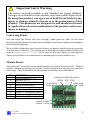
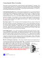
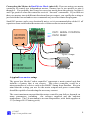
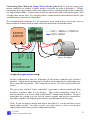
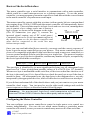
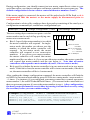
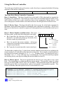
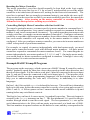
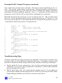
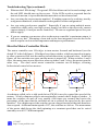
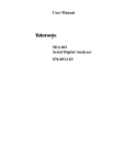
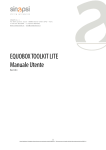
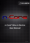
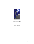
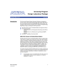
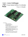
Low-Voltage
Dual Serial Motor Controller
User’s Guide
Contents:
Safety Warning
Contacting Pololu
Module Pinout
Connecting the Motor Controller
Basics of the Serial Interface
Configuring the Motor Controller
Using the Motor Controller
Example BASIC Stamp II Program
Troubleshooting Tips
How the Motor Controller Works
Description and Specifications
Pololu
© 2005
http://www.pololu.com/
SMC05A
!
Important Safety Warning
The motor controller module is not intended for young children!
Younger users should use this module only under adult supervision.
By using this product, you agree not to hold Pololu liable for any
injury or damage related to the use or to the performance of this
product. This product is not designed for, and should not be used
in, applications where the malfunction of the product could cause
injury or damage.
Contacting Pololu
You can check the Pololu web site at http://www.pololu.com/ for the latest
information about the motor controller, including color pictures, application examples,
and troubleshooting tips.
We would be delighted to hear from you about your project and about your experience
with our motor controller. You can contact us through our online feedback form or by
email at [email protected]. Tell us what we did well, what we could improve,
what you would like to see in the future, or anything else you would like to say!
Module Pinout
The function of each of the nine module terminals is listed in the table below. With the
module components facing you and the contacts facing down, the pins are numbered
left to right. The pin functions are also printed on the back side of the module.
PIN
1
2
3
4
5
6
7
8
9
FUNCTION
motor supply (0-7 V)
ground (0 V)
logic supply (3.0-5.5 V)
serial control input
reset
motor 1, positive output
motor 1, negative output
motor 0, negative output
motor 0, positive output
serial port interface pins:
SERIN RST GND
mounting
mounting
hole
hole
motor 0 LEDs
motor 1 LEDs
12 3 4 5 6 7 8 9
Pololu
© 2005
http://www.pololu.com/
2
Connecting the Motor Controller
The motor controller module has connection holes with a standard 0.1" spacing. You
can solder in pins with the same spacing to use the module with a solderless breadboard
or prototyping board. However, soldering wires directly to the board is recommended,
especially for high-current installations. For the high-current terminals (1,2 and 6-9),
use the thickest and shortest wire possible.
Connecting Power (pins 1-3). Connect the ground pin (pin 2) to a ground terminal on
your main controller unit and to the negative terminal of your motor power source.
Connect the positive terminal of your motor power source to pin 1. Connect your logic
power supply to pin 3. The logic power supply is the voltage at which your main
controller operates, such as 5 V. You can connect the same power source to both logic
and motor supplies. For example, if you are using a microcontroller that can run at
4.5 V, you could run both your logic and motors off of three 1.5-volt batteries.
Warning: make sure the motor supply does not exceed 7 volts and the logic supply
does not exceed 5.5 volts.
Reset Input (pin 5). The reset input must be kept high (at the logic supply voltage) for
the motor controller to operate; bringing it low (to 0 V) for a brief moment (at least a
few microseconds) resets the motor controller to its initial state (all motors off, waiting
for its first serial command). Connect this pin to a digital output on your main
controller. This connection is not required, but we strongly recommend using the reset
line; you might also use a pull-down resistor on the reset line so that if your main
controller gets reset, the motors do not keep running.
Serial Input (pin 4). Use a pin on your main controller that can be used as a logiclevel, asynchronous serial output. Serial data can be sent down this line 8 bits at a time,
with no parity bit, at any rate between 1200 and 19200 baud. Once you choose a baud
rate, you cannot change it until the motor controller is reset. Important note: unlike
RS-232 serial lines (the standard for serial ports used to connect devices to personal
computers), this line uses logic voltages between 0 and the supply voltage. The higher
voltages used on RS-232 lines will damage the motor controller. If you need to connect
to a serial port on the computer, see the section below.
RS-232 (COM port) connection. The motor controller features an integrated levelconverter for both the serial and reset control lines. To use the converter, use the three
serial interface pins at the top of the board. The reset line is
again optional, but it can be used with one of the handshaking DB9 serial
port connector
lines (DTR, pin 4, or RTS, pin 7). In some cases, it might be
1
necessary to connect the handshaking lines as shown. When
6
building circuits that connect to a PC, be especially careful
2
7
because you could potentially destroy the PC’s serial port.
3
SERIN
Before attempting to connect your own electronics to a
8
computer, make sure you know what you are doing!
4
RST
9
5
Pololu
© 2005
http://www.pololu.com/
GND
3
Connecting the Motors in Dual Motor Mode (pins 6-9). If you are using your motor
controller to control two independent motors, connect one or two motors to pins 6
through 9. You probably don’t need to worry too much about the polarity, but pins 6
and 9 go positive when the controller receives “forward” commands. If you find out
that your motors turn in different directions than you expect, you can flip the wiring or
just switch the forward and reverse commands on your robot controller program.
Small DC motors can be very electrically noisy, so it is recommended to solder 0.1 uF
capacitors from each lead to the motor case or between the two motor leads.
OUT1: SERIAL CONTROL
OUT2: RESET
MOTOR
BATTERY
0.1
0.1
OUT2
OUT1
Vcc
GND
Up to 5 Amps
0.1
ROBOT
CONTROLLER
Up to 5 Amps
A typical two-motor setup.
The green box labeled “robot controller” represents a main control unit that
includes a battery that is not shown. This robot controller could be a
microcontroller or a device such as the BASIC Stamp from Parallax. Keep in
mind that the wiring you use for the motor outputs and power connections
should be capable of conducting the necessary current.
The exact maximum current that the motor controller can deliver depends on
many parameters, including
the voltages supplied and the ambient
temperature. The 5 A maximum is at room temperature, with both supplies at
5 V (a charged 4.8 V battery pack).
Pololu
© 2005
http://www.pololu.com/
4
Connecting One Motor in Single Motor Mode (pins 6-9). If you are using your
motor controller to control a single motor, you must use pins 6 through 9. Before
connecting the single motor, make sure that you have configured the motor controller
for single motor mode. Connect pins 6 and 9 to one motor lead, and connect pins 7 and
8 to the other motor lead. If you make these connections in dual-motor mode, you
could destroy your motor controller!
We recommended soldering 0.1 uF capacitors from each lead to the motor case or
between the two motor leads to limit electrical interference from the motor.
OUT1: SERIAL CONTROL
OUT2: RESET
MOTOR
BATTERY
0.1
0.1
OUT2
OUT1
Vcc
GND
Up to 10 Amps
ROBOT
CONTROLLER
A typical single-motor setup.
In this configuration, the two H-bridges of the motor controller are wired in
parallel. Single-motor mode must be used to ensure that the two H-bridges are
also controlled in parallel. This setup allows up to 10 A to be delivered to the
motor.
The green box labeled “robot controller” represents a main control unit that
includes a battery that is not shown. This robot controller could be a
microcontroller or a device such as the BASIC Stamp from Parallax. Keep in
mind that the wiring you use for the motor outputs and power connections
should be capable of conducting the current you intend to have flowing.
Note: If you are using a motor that draws less than 5 A, you do not have to use
single-motor mode! In other words, you don’t have to have two motors
connected just because you are in dual-motor mode.
Pololu
© 2005
http://www.pololu.com/
5
Basics of the Serial Interface
The motor controller uses a serial interface to communicate with a main controller,
which could be a small microprocessor or a desktop computer. To use the motor
controller, you must program your main controller to send data with the correct format
to the motor controller’s asynchronous serial input.
The motor controller expects eight bits at a time (with no parity bit) at a constant baud
rate ranging from 1200 to 19200 baud (the motor controller will automatically detect
the baud rate). The serial bits must be at logic levels and non-inverted, meaning that a
zero is sent as a low voltage, and a one is sent as a
LSB
MSB
high voltage, as shown in the diagram to the right.
(The PC-connection (see page 3) corrects the 5V
10011010
inverted signal coming out of PC serial ports.)
Commands sent to the serial input must conform to 0V
the above format or else the motor controller and
start bit
stop bit
other devices connected to the serial line may
behave unexpectedly.
Once you can send individual bytes correctly, you must send the correct sequence of
bytes to get the motor controller to run your motors. This motor controller interface
protocol is compatible with other Pololu serial devices such as our servo controllers, so
you can control multiple Pololu serial devices on a single line. The protocol requires
one start byte, a one-byte device identifier, and then any number of bytes, as required by
the device specified in the second byte:
start byte = 0x80
device type
data byte 1
data byte 2
The start byte is identified by its most significant bit being set; all subsequent bytes
must have bit 7 clear, giving them possible values of 0 to 0x7F (0 to 127 decimal).
Whenever a byte is transmitted on the serial line, all devices on that line check to see if
the byte is the start byte; if it is, then all devices check the next byte to see if the data is
meant for them. All subsequent bytes, the data bytes in the diagram above, are only
interpreted by the appropriate devices, while all other devices wait for a new start byte.
If you did not understand all of the details above and you just want to use your motor
controller, don’t worry. You just need to use the right serial settings and send the
correct sequences of bytes, as described on the following pages.
Summary: Use non-inverted, logic-level serial transmission at baud rates
between 1200 and 19200, 8 bits at a time with no parity and one stop bit.
Configuring the Motor Controller
You can configure your motor controller to control a single motor or to control two
motors independently. You can also set which motor number a particular motor
controller will control, in case you want to control many motors off of one serial line.
Pololu
© 2005
http://www.pololu.com/
6
During configuration, you should connect just one motor controller at a time to your
serial line unless you want to configure each motor controller the exact same way. The
default configuration is for two-motor control with motor numbers 2 and 3.
If the motor supply is connected, the motors will be pulsed as the LEDs flash, so it is
recommended that the motors or the motor supply be disconnected prior to
configuration.
Configuration is achieved by sending a three-byte packet consisting of the start byte, a
configuration command byte, and the new configuration byte:
start byte = 0x80
change configuration = 0x02
The new settings byte contains two parts: a six-bit
motor number and a one-bit flag specifying onemotor or two-motor mode.
"
"
bit 7
new settings, 0x00-0x7F
bit 0
0x x x x x x x
Bits 0-5 specify the motor number(s) to which
the motor controller will respond. In singlebits 0-5: motor
motor mode, the number you choose sets the
number
bit 6: # of motors
number to which the motor controller will
1 = 1 motor
respond. In two-motor mode, the motor
0 = 2 motors
controller will respond to two consecutive
bit 7: always 0
numbers. If you set an even motor number,
the motor controller will control that motor
number and the one above it; if you set an odd motor number, the motor controller
will control that motor number and the one below it. Note that all motor
controllers will respond to motor number 0 (and 1, if in two-motor mode).
Bit 6 specifies whether the motor controller is in one-motor mode or in two-motor
mode. If this bit is clear, the motor controller will be in two-motor mode; if the bit is
set, the motor controller will be in 1-motor mode.
After sending the change configuration command, the motor controller will flash the
red LED for one-motor mode and the green LED for two-motor mode <motornumber>
+ 1 times. For instance, if you configured your motor controller to control one motor,
motor number 3, the red LED should flash 4 times. (The reason for the extra flash is so
that you get some response if you set the motor number to zero). After configuration,
the motor controller must be reset (either by turning it off and back on or by using
the reset line) before you can continue using it.
Examples: (Using PBASIC “SEROUT” command with serial line on pin 5)
‘ “84” parameter sets up 9600 baud serial communication
SEROUT 5, 84,[$80,2,2]
‘2-motor mode, controlling motors 2 and 3
SEROUT 5, 84,[128,2,68]
‘1-motor mode, controlling motor 4
SEROUT 5, 84,[$80,$2,$44] ‘same as above, using hexadecimal
Pololu
© 2005
http://www.pololu.com/
7
Using the Motor Controller
To set the speed and direction of a motor, send a four-byte command with the following
structure to the motor controller:
start byte = 0x80 device type = 0x00 motor # and direction motor speed
The Four-Byte Motor Controller Command
Byte 1: Start Byte. This byte should always be 0x80 (128 in decimal) to signify the
beginning of a command. The start byte is the only byte with the highest bit (bit 7) set,
and it alerts all devices on the serial line that a new command is being issued. All
succeeding bytes sent down the serial line must have their highest bit cleared to zero.
Byte 2: Device Type. This byte identifies the device type for which the command is
intended, and it should be 0x00 for commands sent to this motor controller. All devices
that are not dual motor controllers ignore all subsequent bytes until another start byte is
sent.
Byte 3: Motor Number and Direction. This byte
has three parts, as shown in the diagram to the right:
"
"
"
bit 7
bit 0
0x x x x x x x
Bit 0 specifies the direction of the motor. Set
this bit to 1 to make the motor go forward; clear
the bit to make it go backward.
Bits 1-6 specify the motor number. All motor
controllers respond to motor number(s) 0 (and 1,
in dual-motor mode).
Bit 7 must be cleared since this is not a start byte.
bit 0: direction
1 = forward
0 = reverse
bits 1-6: motor
number
bit 7: always 0
To obtain the complete byte 3 value from a motor number and a direction, multiply the
motor number by 2 and add 1 if the direction is forward. For example, to make motor 5
go forward, byte three should be 5 x 2 + 1 = 11. To make motor 1 go backward, byte 3
should be 1 x 2 = 2. (Two efficient ways to multiply by 2 in a microcontroller program
are shifting left by one digit or adding the motor number to itself.)
Byte 4: Motor Speed. The most significant bit must be zero since this is not a start
byte. The remaining seven bits specify the motor speed. The possible range of values
for byte 4 is thus 0x00 to 0x7F (0 to 127 decimal). 0x00 turns the motor off, and 0x7F
turns the motor fully on; intermediate values correspond to intermediate speeds. The
motor will brake when the speed is set to 0 in forward or reverse.
Examples: (Using PBASIC “SEROUT” command with serial line on pin 5)
‘ “84” parameter sets up 9600 baud serial communication
SEROUT 5, 84,[$80,0,5,127] ‘motor 2 full on, forward
SEROUT 5, 84,[$80,0,5,0]
‘motor 2 brake (off)
SEROUT 5, 84,[$80,0,4,64]
‘motor 2 reverse, half speed
Pololu
© 2005
http://www.pololu.com/
8
Resetting the Motor Controller
The motor controller’s reset line should normally be kept high at the logic supply
voltage. Pull the reset line low to 0 V for at least 2 microseconds to reset the motor
controller to its initial state (all motors off, waiting for the first serial command). The
reset line is optional, but we strongly recommend using it; you might also use a pulldown resistor on the reset line so that if your main controller gets reset, the motors do
not keep running. After turning on the motor controller or resetting it, allow
100 ms for it to start up before sending any serial data.
Controlling Multiple Motor Controllers with One Serial Line
To control a particular motor, you must specify its motor number in command byte 3.
Regardless of configuration, every motor controller responds to commands for motor
number 0, and, in two-motor mode, for motor 1. To control more than two motors with
a single serial line, you need to use motor numbers 2 through 63. Configure each motor
controller to respond to different motor numbers, then connect them to the same serial
line; each motor controller will respond only to the motor number to which it is
configured. After you configure a motor controller, you can write its motor number on
a label to keep track of your motor numbers.
For example, to control six motors independently with dual-motor mode, you need
three motor controller boards, each with different motor numbers. All three motor
controllers respond to commands for motor numbers 0 and 1. For controlling the six
motors independently, use motor numbers 2, 3, 4, 5, 6, and 7. (In single-motor mode,
you would need six motor controllers configured to numbers 1 through 6 since only
motor number 0 is a universal motor number.)
Example BASIC Stamp II Program
The program on the next page, which can run on a BASIC Stamp II controller, makes
motor 1 gradually speed up, then slow down, then speed up in the other direction, and
then slow down again. For the code to work, pin 15 must be connected to the reset input
(pin 5), and pin 14 must be connected to the serial input (pin 4). The interface code
should look similar in other programming languages; the description below should
help you in understanding the code and, if necessary, in translating it to other
languages.
On line 1, the 8-bit variable speed is declared for later use. The serial line is then taken
high, to its idle state, before the motor controller is reset by a low-going pulse on pin 15
(lines 3 and 4). A 100-ms pause on line 5 ensures that the motor controller is up and
running before any serial data is sent to it.
The first for loop on lines 6-9 causes motor 1 to gradually speed up. The serial output is
created by the serout statement on line 7. The first parameter, 14, specifies the pin
number through which to send the serial signal. The next parameter, 84, sets up the
serial characteristics to be 8 bits with no parity, non-inverted, at a baud rate of 9600.
The four numbers in square brackets are the data to be sent, and they correspond to the
Pololu
© 2005
http://www.pololu.com/
9
Example BASIC Stamp II Program (continued)
four control bytes for the motor controller. The first two bytes should always be $80
and 0. The second 0 makes motor 1 go backward. The speed variable, which increases
every time through the loop, is the only part of the command that changes, and that is
what makes the motor gradually speed up. The pause statement on line 8 causes the
program to wait for 20 ms (0.02 seconds) before sending the next command.
When the first loop ends, the motor is set to its full speed of 127. The second loop on
lines 10-13 slows the motor back down by sending speeds from 127 down to 0. The
next two loops on lines14-21 then repeat the process, except for the parameter value of
1 in byte three, which causes motor 1 to spin forward.
speed
var byte
high 14
‘take serial line high
low 15
‘reset motor controller
high 15
pause 100
‘motor controller startup time
for speed = 0 to 127
serout 14,84,[$80, 0, 0,speed]
pause 20
next
for speed = 127 to 0
serout 14,84,[$80, 0, 0,speed]
pause 20
next
for speed = 0 to 127
serout 14,84,[$80, 0, 1,speed]
pause 20
next
for speed = 127 to 0
serout 14,84,[$80, 0, 1,speed]
pause 20
next
1
2
3
4
5
6
7
8
9
10
11
12
13
14
15
16
17
18
19
20
21
Troubleshooting Tips
All motor controllers are fully tested prior to shipment; if your motor controller does
not work at first, it can be difficult to determine the cause. Nevertheless, patience and
meticulous attention to detail, along with these tips, should usually help you through.
"
"
Double check all of your connections. Are your logic and motor supply grounds
connected? If you are using a breadboard or connectors, are the motor controller
pins all making good contact?
Double check your code. Are your baud rate settings correct? If you cannot get
your design working with the top baud rate of 19200, try lowering it to 9600, where
slight timing mismatches are less likely to frustrate your efforts.
Pololu
© 2005
http://www.pololu.com/
10
Troubleshooting Tips (continued)
"
"
"
"
What are the LEDs doing? The green LED should turn on for forward settings, and
the red LED should turn on for reverse. If the LEDs work as expected but the
motors do not run, it is possible that the motor drivers have burned out.
Are you using the correct motor number? If nothing seems to be working, start by
using motor number 0, which should work regardless of the configuration.
Are you using good power supplies? Especially if you are using multiple motor
controllers, make sure your logic power supply can deliver the necessary current
(approximately 10 mA per motor controller). Do not use regulated power for your
motor supply.
If you are running your motors close to the motor controller’s maximum output, it
will get very hot. Mounting a heat sink to the four integrated circuits above the
motor outputs can lower the temperature and improve performance.
How the Motor Controller Works
The motor controller uses H-bridges to turn motors forward and backward (see the
dotted ‘H’ in the left figure). H-bridges have four switches, which are turned on in pairs
to allow current to flow into the motors in both directions, as shown below. In the left
figure, all four switches are open, and the motor is turned off. When switches 1 and 4
close, the motor turns in one direction; when switches 2 and 3 close, the motor turns the
other way. The dual serial motor controller contains two H-bridges, allowing
bidirectional control of two motors.
V+
1
V+
2
1
V+
1
2
M
M
3
4
V-
2
M
3
4
V-
3
4
V-
A technique called pulse width modulation (PWM) is used to control the speed of the
motors. A little computer called a microcontroller controls the H-bridge switches. It
turns the switches on and off very rapidly (600 times per second) and varies the
percentage of the time that the switches are on to achieve the speed set by the serial
interface. For a higher speed, the switches are on a larger fraction of the time than for a
slower speed. At the maximum speed of 127, the switches are left on. The momentum
of the motor shaft keeps the shaft spinning at a constant speed that can be varied
smoothly over all 127 different speeds.
Pololu
© 2005
http://www.pololu.com/
11
The Pololu Low-Voltage Dual Serial Motor Controller
For a robot to interact with its environment, it must be able to convert
electrical signals into motion. However, the power requirements of
actuators, electrical devices capable of producing motion, are typically
so high that normal digital circuitry cannot drive them. In addition,
precise motion control requires constantly changing the signals sent to
the actuators, leaving the control circuitry with little time to attend to
other tasks.
The Pololu motor controller bridges the gap between robot controllers
and power-hungry actuators. Using one serial output from your robot
controller, you can independently set each of two small DC motors (the
kind typically found in remote-control cars and motorized toys) to go
forward or backward at any of 127 different speeds. To control
additional motors, you can connect multiple motor controllers to the
same serial line. The motor controller is compatible with the Pololu
servo controllers, so you can control an almost unlimited number of
motors and servos with one serial line.
The low-voltage aspect of the motor controller makes it especially suited
for robots and mechanisms that use low-cost toy motors that run at low
voltages but high currents. This motor controller has no minimum
motor supply voltage, and it can deliver up to 5 amps per motor.
Specifications
PCB size.................................
Motor ports.............................
Speeds....................................
Maximum current...................
Motor supply voltage.............
Logic supply voltage...............
PWM frequency......................
Serial baud rate.......................
Pololu
© 2005
http://www.pololu.com/
0.90" x 1.0"
2
127 forward and backward, brake (off)
two motors 5 A each, one motor 10 A
0-7 V
3.0-5.5 V
two motors 600 Hz, one motor 750 Hz
1200-19200 (automatically detected)
12