1
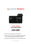
VEHICLE CCTV AND SAFETY SYSTEMS
VEHICLE JOURNEY RECORDER
SVC100GPS
SVC100GPS-LCA
SVC100GPS-LCA2
User Guide
www.smartwitness.com
1
CONTENTS
GPS Function ..............................................................................
5
1. Overview ................................................................................
6
SVC100GPS ..................................................................
7
SVC100GPS-LCA/-LCA2 ...............................................8
SVC100GPS-LCA/-LCA2 - Wiring Description ..............
9
2. Contents ................................................................................
10
3. Software Installation ..............................................................
11
4. SD Card Insert .......................................................................
SD Card Care ................................................................
12
15
5. Product Installation ..............................................................
16
SVC100GPS ..................................................................
16
SVC100GPS-LCA/-LCA2 ..............................................16
6. LED Guide .............................................................................
17
7. Camera Functions ................................................................
Camera Operation .........................................................
18
19
8. Software User Guide ............................................................
20
PC Viewer Setting .........................................................
20
File Loading ...................................................................
21
Playback Screen ...........................................................
23
Playback .......................................................................24
Google Maps ................................................................
26
Thumbnail Function ......................................................
27
Save JPG and AVI File .................................................
28
Print Image ...................................................................
29
Reporting ......................................................................30
Backup Event/Log ........................................................
31
Product Information ......................................................
32
Log File Playback .........................................................
33
www.smartwitness.com
CONTINUED...
GPS Log to KML Converter ..............................................
Enhanced Driver Report Function ....................................
34
35
9. Cloud Upload ...........................................................................
47
10. Setting the Journey Recorder .............................................
Speed Dependant G-Sensor ...........................................
User Defined G-Sensor ...................................................
Auto Format Feature .......................................................
Alarm Outputs .................................................................
11. Specifications .......................................................................
48
48
49
50
50
52
Appendices
Appendix 1 - Recording Time Table .........................................
Appendix 2 - Optional Accessory ............................................
Appendix 3 - Firmware Upgrade ..............................................
www.smartwitness.com
53
54
57
SAFETY ADVICE
CAUTION
RISK OF ELECTRIC SHOCK
DO NOT OPEN
DO NOT REMOVE THE COVER
REFER SERVICING TO QUALIFIED SERVICE PERSONNEL
Connect your vehicle’s power cable (Cigarette Jack) to the
product after starting the vehicle to avoid damage.
Install the product where it does not block the driver’s view of
the road. Please refer to the installation section in the user
manual for a full guide on where to install product.
Damages caused by production malfunction, loss of data or
other damages that may occur while using this product is not
the responsibility of the manufacturer. When malfunction
occurs, the product may not save all videos and the sensor
may not recognise shock impacts.
WARNING:
DO NOT EXPOSE PRODUCT TO RAIN OR MOISTURE
4
www.smartwitness.com
GPS RECEPTION
1. Activate the product in an area without large buildings to improve
GPS reception.
For commercial purposes GPS has an average range error of more than 15
meters and the range error could be more than 100 meters depending on
environmental conditions like buildings and roadside trees etc.
2. The temperature range for optimum operation of the GPS receiver in
your car is -10 ~ 50°C.
3. When using the product for the first time or after a long period (more
than three days), it may take a little longer to recognise your current
location.
It may take between five and thirty minutes to get GPS reception.
GPS reception may be impaired under the following circumstances:
1) If there is an object at the end of the GPS antenna
2) If your vehicle has metallic elements on the windshield
3) If equipment generating electromagnetic waves that interfere with the GPS
signal are installed in the vehicle e.g. other GPS devices including certain
types of wireless activated alarms, MP3 and CD players and camera
alarms using GPS.
4) If you are using a receiver connected by a cable, electrical interference can
be avoided by simply changing the location of the receiver (antenna).
5) On heavily overcast or cloudy days, if the vehicle is in a covered location
such as under a bridge or raised roadway, in a tunnel, an underground
roadway or parking area, inside a building or surrounded by high-rise
buildings.
6) If GPS signal reception is poor, it may take longer to locate your current
position when the vehicle is moving than when it is stationary.
www.smartwitness.com
5
1. OVERVIEW
The SVC100GPS-LCA/-LCA2 is a Vehicle Journey/Accident Recorder with
3 Axis Shock Sensor & GPS for measuring braking, acceleration, driving
style and recording location. The unit includes a transparent locking case to
prevent tampering with evidence.
This evidence can protect a driver from many of the issues faced on the
roads today:
•Cash for Crash / Pre-meditated staged accidents
•False/Exaggerated Whiplash Claims
•Conflicting Reports of Actual Events
•Lack of Witnesses
•Driving Offence Allegations (Speed Cameras, Traffic Signal Violations etc...)
Features:
• Continuously records the driver’s view via a 170º high-quality lens
• Continuously records braking/acceleration/collision G-forces
• Approved for installation in commercial vehicles
• Built-in GPS receiver ensures the highest accuracy for vehicle
location and speed
• Simple DIY installation
• E-mark, EMC, CE and FCC approved for extra piece of mind
• VOSA and Data Protection Act compliant
6
www.smartwitness.com
SVC100GPS
FRONT
Bracket
Stick adhesive
tape here
Camera Lens
RIGHT
LEFT
DC Power In
(DC 12V~24V)
Memory
Card Slot
REAR
Record Button
Internal GPS
Antenna
Record LED
Blue LED
SD Card Format
Button
www.smartwitness.com
Overwrite LED
Red LED
7
SVC100GPS-LCA/-LCA2
FRONT
Bracket
Stick adhesive
tape here
Camera Lens
Tamper Resistant
Locking Case
RIGHT
LEFT
Key Lock
Protects SD
Card Slot
DC Power Input
Connected with
permanent wiring
Rear
Record Button
Internal GPS
Antenna
Record LED
Blue LED
SD Card Format
Button
8
www.smartwitness.com
Overwrite LED
Red LED
SVC100GPS-LCA
- Wiring Description
Remote SW+
Remote SWBattery -
Alarm Out (G-Sensor & Panic)
Battery+ (Connect to ignition)
SVC100GPS-LCA2
- Wiring Description
Remote SW+
Remote SWBattery -
Alarm Out (G-Sensor & Panic)
Battery+ (Connect to ignition)
Alarm Out (SD Card Fault)
For further information, please contact your installer.
If you want to power your camera permanently, please see Appendix 2 on
page 54.
www.smartwitness.com
9
2. CONTENTS
SVC100GPS-LCA/-LCA2
SVC100GPS
SVC100GPS Camera
/Recording Unit including bracket
Wire Splice Clips
Item contains all accessories on
the left, plus the following:
Keys for Locking Case
Sticker for Windscreen
Mounting (Double-sided Tape x 2)
Power Cable (Cigarette Jack)
Spare Mounting Bracket
USB 2.0 SD Card Reader
Spare Mounting Bracket
SD Memory Card*
Transparent Locking Case
Telematics Cable
Please note: The SVC100GPSLCA2 will have an extra alarm
output wire
*SD Card size will depend on the
model and may not be included.
10
www.smartwitness.com
3. SOFTWARE INSTALLATION
Software Installation
(Windows)
Software
Installation
(Windows)
PC SYSTEM REQUIREMENT
Recommended PC specifications for PC Viewer software
OS
CPU
RAM
Interface
HDD Free Space
Display
Windows 2000, Windows XP, Windows Vista,
Windows 7
Pentium4 2.6GHZ or higher
512MB or higher
SD Memory Card Reader
Install 20MB or higher
Backup 2GB or higher
1,024 x 768 pixel / High Colour (16 bit) or higher
If the PC does not meet the minimum system requirements, the Analysis
Software may not function properly.
www.smartwitness.com
11
1. To download the SVC100GPS software, type ‘www.smartwitness.com’
into your browser and go to the support section.
2. Choose ‘Software’ and ‘SVC100GPS’ options from the drop down
menu as shown below.
*Screenshot taken from www.smartwitnes.com
3. Click the ‘Download’ button (file will automatically download to PC).
4. When downloaded, go to the ‘Downloads’ folder and double click the ‘Setup’ file.
5. Select the language and then follow the on screen dialog box.
6. The ‘PCViewer’ icon will now be displayed on your desktop.
NOTE: To Un-install the PC Viewer
Open the ‘Control Panel’
Select ‘Remove Program’ and remove PC Viewer SVC100GPS
12
www.smartwitness.com
4. SD CARD INSERT
PLEASE NOTE
If you have been supplied with an SD card, then
this will need to be setup using the latest Smart
Witness Software.
1. Insert the SD memory card into the computer using the SD card reader.
2. This software can be downloaded from
www.smartwitness.com/article/76/support
3. Once on the page, select the correct software by using the Drop Down
Menu
4. When downloaded, go to the ‘Downloads’ folder and double click the
‘setup’ file.
5. Follow the setup - instructions, then the software icon will appear on your
desktop.
6. Double click the software icon to load the software. (Below)
www.smartwitness.com
13
7. Click the ‘Tool’ button
8. Select the “SD Card Initilize” button from the drop down menu
9. You will be presented with another drop down list to select the card to format.
10. Select the “DRIVERREC” from the drop
down and tick the “Quick Format” box
when prompted.
11. Click “Start” to begin formatting.
12. Once the card has been formatted, you
will see the screen on the right.
Then, remove the SD Card from the
computer.
13. Make sure the unit is turned off before
inserting the SD Card.
14. Insert the SD memory card into the SD
card slot.
PLEASE NOTE
The very first time you power up your unit with the SD Card inserted, it is
important not to disconnect the power before the 2 minutes are up, as this
may damage the unit.
14
www.smartwitness.com
SD CARD CARE
SD cards are a popular recording consumable. They are very robust and
reliable.
However, if they are not correctly maintained their lifespan can be reduced
and the file structure could become corrupt. Maintaining SD cards is quick
and easy and is carried out by regular formatting.
If you ever experience card failure, missing or corrupt recordings, then this is
a sign that the SD card is in need of a format. All makes and models of Micro
SD and full size SD cards require formatting regularly.
AUTO FORMAT FEATURE
The Smart Witness SVC100GPS range has a convenient feature that will
Auto Format the SD card if it detects a card error. The process takes less
than 10 seconds and will delete all data on the card. For this reason we
advise you to immediately remove the card from the unit and take a backup
of an incident that needs to be kept has occurred.
For full details on how to use this feature, please refer to section 10
CARD FAILURE INDICATOR
If the Auto Format feature cannot fix the card issue the card may be faulty. In
this case both LEDs on the unit will be solid for over 20 seconds,
indicating a card fault. The card should then be checked for errors using a
computer. If the card cannot be repaired or formatted by a computer it is
likely that the card will need to be replaced.
PLEASE NOTE
Under no circumstances whatsoever shall Smart Witness be liable for any
indirect or consequential loss or for any loss of profits, loss of business,
depletion of goodwill, loss of data, loss of opportunity, loss of
contract and any similar loss arising from the purchase and use of this
product.
www.smartwitness.com
15
5. PRODUCT INSTALLATION
SVC100GPS
- DIY Fitting
1. Attach the double sided adhesive
tape to the unit.
2. Secure the SVC100GPS to the
windscreen behind the rear view
mirror. Please make sure that the
surface is clean and dry before
attaching.
Tip:
Hold in position
with firm
pressure for
30 Seconds
3. Adjust camera view and make
sure the lens has an unobstructed
view.
4. Arrange the power cord neatly
alongside the windshield and
door pillar trim. Use the provided
wire splice clip.
5. Connect the SVC100GPS to the cigarette
lighter socket.
SVC100GPS-LCA-LCA2
- Professional Installation Recommended
Please don’t attempt to permanently wire this unit
unless you are familiar with auto wiring.
Any incorrect installations will not be covered by
the warranty.
16
www.smartwitness.com
For a full wiring description,
please see section 2.1.
6. LED GUIDE
Blue LED
Red LED
See the table below for an explanation of the LED status changes on the
back of the recorder.
No.
BLUE LED
RED LED
Meaning
1
Blink every half second
OFF
Event Recording
2
Blink every 4 seconds
OFF
Continuous Recording
3
Solid
OFF
Pre-Recording
(Awaiting Triggers)
4
OFF
Blink every half second
Card Fault
5
SOLID
SOLID
System Booting Up
6
Blink every half second Blink every half second
Unit Fault
7
SOLID
OFF
SD Card Removal
in Safe Mode
8
OFF
OFF
No Power
www.smartwitness.com
17
7. CAMERA FUNCTIONS
Auto Start Function
Connect your vehicle’s power cable to the SVC100GPS after starting the
vehicle and the SVC100GPS will automatically start.
(Use the provided power cable.)
PLEASE NOTE
The unit will not start recording immediately after power on. It takes around 1
minute for the built-in power backup system to charge. Thereafter, the
internal flash memory will be ready to record.
Event Recording
The event recording will be automatically started by the G-sensor.
The G-sensor sensitivity can be set by your PC. To set the G-Sesnor
Sensitivty, please refer to section 10 - Setting the Vehicle Journey
Recorder. Each event file contains 15 seconds prior & 5 seconds post event.
Manual Recording
Press the [RECORD] button to begin recording manually. Each manual file
contains 15 seconds prior to activation & 5 seconds post activation.
Continuous Recording
The continuous recording will be automatically started after the unit is turned
on. The SVC100GPS doesn’t make a separate event file during the
continuous recording. It will mark the Event area by the G-sensor or Record
button in the continuous recording file which can be easily searched for
during playback.
Built-in power backup (Super Capacitor)
When power to the unit is interrupted, the SVC100GPS creates the last file
using the internal Super Capacitor. This will ensure that no vital information
is lost during that time.
Buzzer
A ‘Beep’ sound will occur when recording starts (this can be turned off if
required).
18
www.smartwitness.com
Camera Operation
Event Record
1. Connect your vehicle’s power cable to the SVC100GPS after starting the
vehicle.
2. Blue LED & Red LED will be slowly blinking simultaneously and then the
Blue LED will remain on. The Blue LED light means SVC100GPS is
ready for the event recording.
3. The event recording will automatically begin by the G-sensor with one
short “Beep” sound.
4. The manual recording will start by pressing the [RECORD] button.
PLEASE NOTE
Multiple impacts coverage
Flash memory captures the video data from the second impact even as the
first impact is still occurring. It will start writing immediately after the first
recording is finished.
Normal Record
1. Connect your vehicle’s power cable to the SVC100GPS after starting
the vehicle.
2. Blue LED & Red LED will be slowly blinking simultaneously and then the
Blue LED will remain on and flash every 4 seconds.
3. Blue LED light flashing every 4 seconds means SVC100GPS is
recording continuously.
4. The continuous recording (normal recording) will automatically begin just
after the power is turned on.
www.smartwitness.com
19
8. SOFTWARE USER GUIDE
PC Viewer Setting
This setting is for the PC Viewer itself. To set the Recorder, refer to
Section 10.
The ‘Date’ formats and ‘Speed’ unit will be set automatically according to the
PC Windows settings, however it can be changed with this PC viewer setting
menu:
Normal Video
Left/Right Flip
Up/Down Flip
20
www.smartwitness.com
File Loading
When Record Method is set as ‘Event record’
‘G-sensor’
means
recording was
activated
by impact
Check
the event
‘Switch’ means
recording was
activated by
button
Check
all files Button
Load
Button
When Record Method is set as ‘Normal record’
Check
the event
Recording
duration:
The maximum
duration is 10
minutes
Load
Button
Check
all files Button
5. Check the event or normal recorded file from the list using a mouse or
click [All] button. Then click [Load] button.
www.smartwitness.com
21
6. Once you’ve clicked the “Load Button” the “FileList” tab will change to the
“PlayList” tab as shown below.
7. Click the file you wish to playback to play that file. Or click the
button to play all the files continuously.
When Record Method is set as ‘Event record’
Now playback
this file
Check
this button
for
continuous
playback
Return to the
[FileList]
When Record Method is set as ‘Normal record’
Now playback
this file
Check
this button
for
continuous
playback
Return to the
[FileList]
Event data search in the playback file
22
www.smartwitness.com
Playback Screen
When Record Method is set as ‘Event Record’
[POST]: post-recorded frame
[PRE]: pre-recorded frame
Check it for continuous playback
Display frame/Total frames number
Frame size
When Record Method is set as ‘Normal Record’
Event area marking by G-sensor
or button (5seconds per each event)
Google Map location
data only available
with SVC100GPS
model
Playback position indicator
www.smartwitness.com
23
Playback
7. Click play button for playback.
GPS Speed,
G sensor data & GPS location
data
Playback Speed
Date & Time
Drag & Move the white bar to move the
playback position.
Before 15 seconds
After 5 sec
Event
Playback Buttons:
X2, 4, 8, 16
Fast Reverse
Previous
Image
X0.5, 1
Reverse
X0.5, 1
Play
Pause
X2, 4, 8, 16
Fast Forward
Next
Image
Zoom In G-sensor graph
Single View
24
4x4 Multi-view
(Thumb-nail
function)
www.smartwitness.com
Reset Zoom
Zoom Out G-sensor
graph
NOTE: PC keyboard hot buttons
Function
PC keyboard hot buttons
1024x768 mode
Enter
Return to the previous mode: Enter
Full Screen Mode
Alt + Enter
Return to the previous mode: Enter
Playback Speed Control
Crtl + F
0.5 => 1
Reverse Playback Speed Control
Ctrl + B
0.5 => 1
Pause / Play
Space
Previous Image
Next Image
→ Direction Button
← Direction Button
www.smartwitness.com
25
Google Maps
The route taken will be displayed on the Google map located at the lower
right corner of the software.
To see the route &
position on Google
Maps, the GPS data
should be recorded with
video.
To see Google Maps, the
PC should be connected
to the Internet.
The Playback position
will be shown on the map
with an arrow. The blue
markings show the route
taken.
Double click the blue
mark to change the video
playback position to that
point.
The camera icon indicates that there is a
recorded file.
The total camera icons
shown will be less than
100, even if there are
more than 100 events.
When the unit is set to
‘Normal’ recording mode,
there will be no route &
camera icon on the map.
26
www.smartwitness.com
Thumbnail Function
8. Click the button for 4x4 multi-view (Thumbnail function)
Click the thumbnail image to change the playback position.
Click the right mouse button to select single image playback mode.
9. Click [Close] button to quit the playback.
Click [Close] to finish the playback.
Then the [PlayList] window will be
changed to the initial status.
www.smartwitness.com
27
Save JPEG and AVI File
10. Pause the playback and click ‘Save Image’ icon to make a JPG file.
‘Save Image’ Icon
11. Click ‘Save AVI’ icon to make a AVI file.
‘Save AVI’ Icon
28
www.smartwitness.com
Print Image
12. Pause the playback and click ‘Print Image’ icon.
‘Print Image’ Icon
Type in the File Name [Print Title] & any comments [Print Comment] using
the Keyboard.
The ‘Print Comment’ window allows up to 7 lines in total.
www.smartwitness.com
29
Reporting
13. Click [Print] button in the print preview windows for printing.
The File Name [Print Title], Comment [Print Comment], G-sensor graph & map will be printed on the first page.
Click [ 2x2 ] and then click [Print] to print 4 images on one page.
30
www.smartwitness.com
Backup/Event Log
14. Click [Backup Event/Log files] icon to backup the files to the PC.
‘Back Up’ Icon
Select [Event data] or [Normal data] and select [Log data] first, before
clicking the [Backup Event/Log files] icon. Then selected Event, Normal or
Log data lists are on the Backup windows.
To backup the whole data from SD card to the PC, check [Backup All]
www.smartwitness.com
31
Product Information
15. Click [About] icon to check the product information.
‘About’ icon
32
www.smartwitness.com
Log File Playback
16. Select [LOG] windows and then check the log from the log list using
mouse or click [Check All] button. Then click [Load] button.
Log Data: Log data will be recorded during driving even if there are no
events. The total log data size is no more than 60MB. The log data
overwrites the oldest data when 60MB is reached. Using this log data, we
can use the data sorting function which helps to find specific data, i.e, more
than 80mph (or 80km), for example.
Search button
Input sorting data
G-sensor graph
GPS speed, G-sensor X value, G-sensor Y value, G-sensor Z value,
can be checked first on the small check box at right side of each value.
Then input the data for data sorting. If there is recorded video data, [Switch]
or [G-Sensor] mark will be displayed on list.
G-sensor X value: Front & Back (e.g Quick brake or Quick Start)
G-sensor Y value: Left & Right (e.g Quick Turn)
G-sensor Z value: Up & Down (e.g. Prominence and Depression)
www.smartwitness.com
33
GPS Log to KML Converter
To see the whole route on Google Earth, select the log file and click the
Google Earth icon, as shown below.
STEP 1. Install Google Earth on your PC.
(http://www.google.com/ earth/)
STEP 2. Check the log file
STEP 3. Click the Google Earth button
The route will then be shown on
Google Earth. We recommend you
use Google Earth Version 5.0 or
above.
Tip: Click [Car Track] and then
Click [Play Tour] button
34
www.smartwitness.com
Enhanced Driver Report Function
The SVC100GPS offers an Enhanced Driver Report (EDR) function.
The EDR function uses driving data: Speed, G-Sensor and GPS recorded by
the SVC100GPS to analyse and quantify driving information for a set amount
of time to highlight driver safety and economy issues.
To use the EDR function:
Make [program] folder at SD root folder as below
1. Launch the SVC100GPS/-LCA PC Viewer Software.
2. Select the data folder by clicking [file] on the tool bar and selecting the
SD Card.
Click the [Tool] button and scroll down and click [Driver Report] function.
www.smartwitness.com
35
The below screen will pop up showing a list of the data files.
Data File List and Calendar
All the dates that contain data will be highlighted in blue. Click on the date
you wish to view and all the data from that day will be listed on the Data
FileList section.
Check the data files from the data file list on the right hand side of the screen. Then click [Load] to view. The graphs will be shown as above.
36
www.smartwitness.com
A. Data File List Control Buttons
[Select All], [Unselect]: Use the [Select All] button to select all the data in the
data list. Similarly, use the [Unselect] button to unselect checked data.
[Load]: This button should be used to load the selected data.
B. Drive Data Graph
The Drive Data Graph displays Speed and G-Sensor information for the
file selected by the user.
1) Speed
The axis on the left hand side indicates Speed. The Scale can be configured
in the Setup Menu.
The Speed is shown as the red line on the graph.
The colour key at the top of the page explains the progress bars on the
bottom of the graph.
Driving / Idling – The Blue line shows the driver is on the move and the grey
line shows when the driver is stationary [Idling]
Speeding (ECO) / Speeding – The Eco speed limit is determined by what
ever speed the driver deems to be Economical. The Green will appear on
the graph when the driver is exceeding the eco-speed limit. The Red line will
appear when the driver is exceeding the actual speed limit.
Eco RPM / Excess RPM function only available with the SVC400GPS
Recorder.
www.smartwitness.com
37
2) G-Sensor Graph
The axis on the left hand side of the graph above indicates the acceleration
force in gs (1g = 9.81m/s2)
The Red line on the graph displays the G-Forces forces from
acceleration/deceleration (X axis)
The Green graph line displays the left and right G-Forces (Y axis)
The Blue line on the graph displays the Up/Down G-Forces (Z axis)
The colour key at the top of the graph explains the colours on the progress
bar on the bottom. For example, the Grey bar indicates the driver is driving
under the G-Force threshold. A Red bar will show when the driver exceeds
the G-Force threshold.
Normal / Sdn Start. Accel. Brake: Normal (When the driver is driving
under the G-Force threshold. This will be indicated by a Grey bar. A Red bar
will appear if a sudden acceleration, deceleration or turn that exceeds the
G-Force threshold is made.
C. Drive Information
The drive information can be found at the top of screen and shows the data
analysis of the whole journey selected in the data file list.
38
www.smartwitness.com
D. Tools
There are 3 tools offered in this function; (From left to right) Zoom, Map and
Print Daily Report.
1) Zoom
When you click the zoom button on the tool bar of the graph, the screen will
pop up as shown above. The user can zoom in on a certain part of the drive
data by clicking the point on the graph they wish to see.
The user can use the arrow keys to advance or retreat from the pre-selected
point in time.
www.smartwitness.com
39
The user can also print out the detailed Zoomed Graph Report by
clicking the [Print] button in the bottom right corner (Below).
40
www.smartwitness.com
2) Driving Map
Click on the Driving Map button on the tool bar to view the driving map
(above).
This will bring up a map showing the whole route of the selected data. When
clicking on a certain point on the Drive data graph, an orange arrow will
indicate the location at that certain point on the map.
www.smartwitness.com
41
3) Daily Report Function
When the Daily Report Button is clicked, a report (below) will print, showing
an analysis of the data file selected. The analysis will cover distance
travelled, average speeds, G-Forces etc and give an economy score and
an overall Driver Score.
F. Set up
To continue the function and display, click the [setup] button on the bottom
right corner of the main display screen.
42
www.smartwitness.com
1) Analysis Criteria Settings
Acceleration/Brake
Scroll down to select the limit for the G-Sensor value for acceleration/deceleration. Any force exceeding this limit will be classified as sudden start or
stop and the unit will start recording.
Speed Limit
Set the speed limit and duration of speeding that you wish to use. For
example, if you drive over 70mph for more than 10 seconds, it will count as
speeding.
Eco Speed Limit
To make the vehicle more economical (i.e. get more miles from less fuel),
the driver can set an economical speed limit. For example, if the driver sets
an eco speed limit of 40mph and exceeds that limit, the driver score will
decrease.
The user can also change the duration at which they exceed that speed limit
for it to count as speeding. For example, if the limit is set at 10 seconds,
the driver would need to exceed 40mph for more than this for it to count as
speeding.
RPM Limit
RPM limit function is only available with the SVC400GPS.
www.smartwitness.com
43
2) Grading Criteria Settings
This sets the grading criteria for each grading category.
The user can set the limit for each parameter which will determine the
driver’s Score. For example, if the settings are as above and the driver
experiences a sudden acceleration for 0.7 times per hour on average, the
driver will get a Grade B in that category.
44
www.smartwitness.com
Point/Weight Settings
The Point/Weight setting can be accessed by clicking on the
button at the bottom right corner of the “Grade Criteria Settings” page.
Point/weight settings sets out the numerical score and weights for each
grade.
For example, if the settings are as above, your B grade for sudden
acceleration will be scored as 80 and since the weight is 14%, your eco
score will be 14% of this – 11.2 points.
Calculation of Safety Score, Eco Score and Total Score
The safety score is calculated by adding up all the weighted points from 7
categories:
Sudden Start count, acceleration count, sudden stop count, speeding count,
speeding duration ratio, peak speed relative to the speed limit and average
speed relative to the speed limit.
www.smartwitness.com
45
Eco-score is calculated by adding up all the weighted points from 5
categories: Sudden start count, acceleration count, sudden stop count,
eco-speeding count and eco-speeding duration ratio.
The total score is the average of the safety score and eco-score.
3) Graph Display Setting
Max Speed: This sets the maximum value of the graph’s speed scale.
Max G-Sensor: This sets the maximum value of the graph’s G-Sensor scale.
Max RPM: This sets the maximum value of the graph’s RPM scale.
(RPM limit function is only available with the SVC400GPS).
Zoom Window Display Time: This sets the time period, in minutes, displayed
on the zoom graph.
46
www.smartwitness.com
9. Cloud Upload
If you have subscribed to our Cloud Upload Service please refer to the Cloud
Upload Service Guide.
www.smartwitness.com
47
10. SETTING THE JOURNEY RECORDER
Speed Dependant G-Sensor
The user can now select the G-Sensor to automatically adjust G-Sensor
value relative to vehicle speed.
For example, if the vehicle brakes when at a high speed the G-force will be
much greater than if the vehicle was to break at a low speed. Therefore, it is
possible that the unit won’t record an incident at a lower speed if the
G-Sensor value is set to high.
By setting the unit to automatically adjust to the vehicle speed the user can
avoid this.
To activate this setting, click the ‘Recorder Settings’ button and
bring up the below screen.
Then check the ‘Auto adjust G-Sensor to Vehicle Speed’ box. This option is
highlighted with the red box.
48
www.smartwitness.com
User Defined G-Sensor
The user defined G-Sensor option allows the user to adjust the G-Sensor
settings to suit your needs.
For example, vehicles that drive slower will have lower G-Sensor threshold
and therefore a custom setting would be more beneficial.
To set the G-Sensor to custom, check the “Custom” option and select the
threshold levels (below).
The user can also use a “Pre-set” G-Sensor option. This allows the user to
set the sensitivity level (between 1-9). Setting the sensitivity at 1 will mean
that the unit will start recording after a heavy impact or turn. Level 9, will
therefore detect a light turn or impact.
The default setting is 5 (medium).
The user can also set the X, Y and Z value sensitivity. To do this, uncheck
the “simple setting mode” option and chose the value from the drop down
menu as shown above.
www.smartwitness.com
49
Auto Format Feature
The auto format feature allows the user to set the SD Card to automatically
format itself if the is an error on the card.
To enable this function in the settings option, check the “Auto Format”
function (Below).
To disable this feature, uncheck the “Auto Format” feature.
Alarm Outs
- SVC100GPSLCA/-LCA2
The Software allows the user to set an alarm input and 2 alarm outputs on
the units. Please note that the second alarm output is only available on the
SVC100GPS-LCA2.
SVC100GPS-LCA
The Alarm Input can be connected to 3rd party devices like a Panic Button.
When triggered, the Alarm Input will mark or start recording on the unit.
The Alarm Output is triggered when either of the following are triggered:
• Alarm Input
• G-Sensor
• Emergency Record button
When this happens the alarm will signal 3rd party devices connected to it,
such as a Tracker or Telematics unit.
To turn this feature on, check the
“AlarmOut1” option in the settings menu.
Please note that the “AlarmOut2” option will
not be clickable for the SVC100GPSLCA.
50
www.smartwitness.com
SVC100GPS-LCA2
The SVC100GPSLCA2 alarm input and outputs work exactly the same as
the SVC100GPSLCA. However, the SVC100GPSLCA2 has an extra alarm
output.
This 2nd Alarm Output will trigger if there is an error with either the SD card
(providing auto format is not turned on) or the unit.
To turn this feature on, check both the
“AlarmOut1” and “AlarmOut2” options
in the settings menu.
Please make sure that the “Auto Format” function has been disabled before
doing this, or the “AlarmOut2’ function won’t work.
www.smartwitness.com
51
11. SPECIFICATIONS
Image Sensor
DSP
Standard DSP
Video Resolution
640x480, 320x240
Recording Speed
Up to 30fps
Recording Modes
Continuous
By Event
By Emergency Button
Angle of View
Recording Time
52
1/4” CMOS
170°
4GB (6 Hours ~ 93 Hours)
16GB (7 Hours ~ 167 Hours)
32GB (15 Hours ~ 500 Hours)
Backup
SD Memory Card
Memory
Supports Cards of up to 32GB
GPS
Internal GPS
G-Sensor
Internal 3-Axis G-Sensor
RTC
Internal Battery
Buzzer
Recording Start, error
LED
2 LEDs (Record, Overwrite)
Super Capacitor
Enable recording of last file and shut down
PC Software
Available from the Smart Witness Website
Power Input
12V to 24V DC
(Cigarette Plug for SVC100GPS)
Power Consumption
3.6W (12V x 300mA)
Size (WxH) in mm
80x50
Weight
0.1 KG
Operation Temp
-10°C~50C
www.smartwitness.com
APPENDIX 1
Recording
VEHICLETime
CCTV Table
AND SAFETY SYSTEMS
Recording/Storage Time Table
Resolution Quality Size
HIGH
40KB
LOW
20KB
HIGH
15KB
LOW
10KB
640x480
320X240
PLEASE NOTE
FPS
2GB
4GB
8GB
1 555 min 1408 min 3115 min
5 111 min 282 min
623 min
10
55 min 141 min
311 min
15
37 min
94 min
208 min
1 1109 min 2816 min 6229 min
5 222 min 563 min 1246 min
10 111 min 282 min
623 min
15
74 min 188 min
415 min
1 1479 min 3755 min 8306 min
5 296 min 751 min 1661 min
10 148 min 375 min
831 min
15
99 min 250 min
554 min
1 2219 min 5632 min 12459 min
5 444 min 1126 min 2492 min
10 222 min 563 min 1246 min
15 148 min 375 min
831 min
16GB
109 hour
22 hour
11 hour
7 hour
218 hour
44 hour
22 hour
15 hour
290 hour
58 hour
29 hour
19 hour
435 hour
87 hour
44 hour
29 hour
32GB
225 hour
45 hour
22 hour
15 hour
445 hour
89 hour
45 hour
30 hour
500 hour
119 hour
59 hour
40 hour
500 hour
178 hour
89 hour
59 hour
Limitation of the event file number
The total number of recorded files must be less than 3,000.
If the SVC100GPS records more than 3,000 files, there is a possibility that
unit will take longer than 1 minute to boot up.
As a result, the maximum recording time is 500 hours, regardless of SD
Card size.
(3,000 files x 10 min = 10,000 min = 500 hours)
www.smartwitness.com
53
APPENDIX 2
Optional Accessory
- Power Cable
Model name: SVCSPWK (SVC100GPS Only)
This cable allows the unit to be permanently wired into the vehicle
Power
Connector
Y Connector
Power On/Off
(Ground Connection)
Switch
12v / 24v Switch
Fuse Cable
Fuse (220v 2A)
Installation
1. Connect the Fuse Cable (+), (the wire with the white dotted line) to the Fuse box in the vehicle. This should be connected to a battery circuit
(i.e. Permanent Power).
54
www.smartwitness.com
2. Connect the black Ground cable (highlighted by the Y pin connector) to
the chasses of the car or ground point.
3. Connect the power connector to the SVC100GPS recorder.
4. To connect the power connector to the SVC100GPS-LCA/-LCA2, please
follow the steps below. Please note, to power these models, you will need
a DCS-B and a DCS-P Connector (available from Smart Witness).
A: Cut the power connector cord on the SVCSPWK.
www.smartwitness.com
55
B: Strip back the wire to reveal the Red (+) and Black (-) wires.
C: Connect the wires to the DCS-B and secure using a screw driver.
Connect the Red wire to the Positive connection and Black to the
negative.
D: Take the SVC100GPS-LCA/-LCA2 unit, and connect the Red (+) and
Black (-) wires to the DCS-P. (Shown Below). Using a screw driver,
connect the Red wire to the Positive connection and Black to the
negative.
E: Secure the DCS-B and the DCS-P together, connecting the
SVC100GPS-LCA/-LCA2 and the SVCSPWK.
4. Finally turn on the Power using On/Off switch located on the unit
(See Fig 1)
56
www.smartwitness.com
APPENDIX 3
Firmware Upgrade
First, upgrade the SVC100GPS/-LCA main unit.
Second, install new PC viewer software on your PC and then initialize the
SD card using new PC viewer software.
1. Preparing Firmware
Make [program] folder at SD root folder as below
Copy “SVC100_X.X.X.bin” file in to the SD card [program] folder.
[NOTE] To get the upgraded firmware, please contact your local distributor.
2. Upgrade SVC100GPS Series
Insert the prepared SD card to SVC100GPS Series and turn on the power.
The Blue & Red LED will be quickly blinking together during upgrading.
There willl be a continuous “Beep” sound during upgrading.
This will take around 2min 30sec.
Do not turn off the power during upgrading.
If the upgrade has failed, the “SVC100GPS/SVC100GPS-LCA” should
be returned to your local distributor.
Once the upgrading is finished, press RECORD button to check
SVC100GPS.
If the SVC100GPS records as normal, turn the power off.
Bring the SD card to your PC and initialize the SD card. To initialize the SD
card, please see section 4 - SD Card Insert.
www.smartwitness.com
57
3. Uninstall the old version PC Viewer from the PC
PC Windows [Start] => [Control panel]
And uninstall [SmartWitness]
4. Uninstall the old version Viewer from the Mac
Drag the Smart Witness file from the applications folder to the recycle bin
and empty the bin.
5. Install the new PC Viewer
Please see section 3 - Software Installation for full installation instructions.
Alternatively, if you have a Mac, please see the Mac Software User Guide.
PLEASE NOTE
After installing the new PC Viewer, initialise the SD card.
Then new software will then be automatically copied to [pcsw] folder on
the SD card.
58
www.smartwitness.com
TECHNICAL SUPPORT & WARRANTY
Technical Support
For Technical Support, please contact your local distributor.
Limited Warranty
This product is supplied with a 2 year warranty. The Warranty excludes
products that have been misused, (including accidental damage) and
damage caused by normal wear and tear. In the unlikely event that you
encounter a problem with this product, it should be returned to the place of
purchase.
www.smartwitness.com
59
Manufactured Exclusively for:
VEHICLE CCTV AND SAFETY SYSTEMS
www.smartwitness.com
Smart Witness, Unit 2 Valley Point, Beddington Farm Road, Croydon, Surrey, CR0 4WP