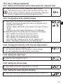
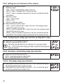
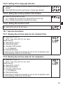
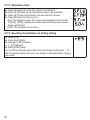
1
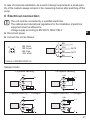
Pin 1
Pin 3
Pin 4
(OUT1)
Pin 2
(OUT2/
InD)
L+
L•Switching signal: limit values for volumetric flow
•Pulse signal: 1 pulse every time the defined volumetric flow quantity is
reached.
•Switching signal: quantity meter reached preset value
•Frequency signal for volumetric flow quantity
•Switching signal: empty pipe detection
•IO-Link
•Switching signal: limit values for volumetric flow
•Switching signal: limit values for temperature
•Analogue signal for volumetric flow quantity
•Analogue signal for temperature
•Switching signal: empty pipe detection
•Input for external reset signal (InD)
Core colours of ifm sockets:
1 = BN (brown), 2 = WH (white), 3 = BU (blue), 4 = BK (black)
7 Operating and display elements
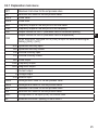
Enter
▲
▼
1 to 8: Indicator LEDs
•LEDs 1-6 = Unit of the currently represented numerical value → 11.1 Reading the
process value
•LED 7 = switching state of output OUT2 / of input InD
•LED 8 = switching status of output OUT1
9: Alphanumeric display, 4 digits
•Current volumetric flow quantity (with setting [SELd] = [FLOW])
•Meter reading of the totaliser (with setting [SELd] = [TOTL])
•Current medium temperature (with setting [SELd] = [TEMP])
•Parameters and parameter values
22