1
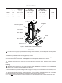
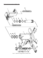
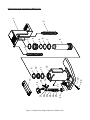
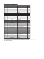
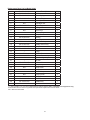
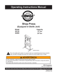
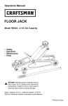
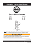
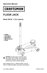
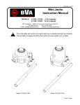
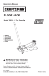
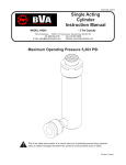
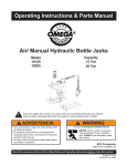
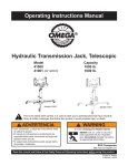
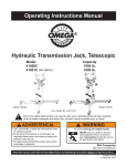
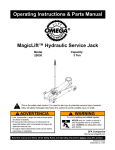
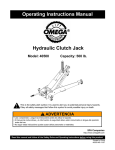
Operating Instructions & Parts Manual
Hydraulic Toe Jacks
Model
13060
13120
13200
!
Capacity
3 Ton
6 Ton
10 Ton
This is the safety alert symbol. It is used to alert you to potential personal injury hazards.
Obey all safety messages that follow this symbol to avoid possible injury or death.
! advertencia
• Leer, comprender, y seguir las instrucciónes antes
de utilizar el aparato.
• El manual de instrucciónes y la información de
seguridad deben estar comunicado en lengua del
operador antes del uso.
• No seguir estas indicaciónes puede causar daños
personales o materiales.
! WARNING
To avoid crushing and related injuries:
NEVER work on, under or around a
load supported only by a hydraulic
jack. ALWAYS use adequately rated
jack stands.
SFA Companies
http://www.omegalift.com
Read this manual and follow all the Safety Rules and Operating Instructions before using this product.
Printed in Taiwan
13060-M0 rev 07/08
Save these instructions. For your safety, read, understand,
and follow the information provided with and on this jack
before using. The owner and/or operator of this equipment
shall have an understanding of this jack and safe operating
procedures before attempting to use. The owner and/or
operator shall be aware that the use and repair of this product
may require special skills and knowledge. Instructions and
safety information shall be conveyed in the operator's native
language before use of this jack is authorized. If any doubt
exists as to the safe and proper use of this jack, remove from
service immediately.
!
WARNING
To avoid personal injury and/or property damage:
• Read, understand and follow all printed materials provided
with and on this jack.
• This is a lifting device only! Never work on, under, or
around a load supported only by a hydraulic jack.
• Immediately support the lifted load with appropriately
rated mechanical means.
• Use only on hard, level surfaces capable of sustaining
rated capacity loads.
• Center load on saddle.
• No alteration shall be made to this device. Use only
attachments, adapters and accessories provided by the
manufacturer.
• Be alert and sober when using this product! Never
operate this equipment when under the influence of drugs
or alcohol.
• Use only high grade hydraulic jack oil in this product.
• Always use a calibrated means of determining how
much force is being applied by this product. Never
exceed the rated capacity of the jack.
Inspect before each use. Do not use if broken, bent, cracked,
or damaged parts (including labels) are noted. Any jack that
appears damaged in any way, operates abnormally or is
missing parts, shall be removed from service immediately. If
you suspect that the jack was subjected to a shock load (a
load dropped suddenly, unexpectedly upon it), immediately
discontinue use until the jack has been checked by a factory
authorized service center (contact distributor or manufacturer
for list of Authorized Service Centers). It is recommended that
an annual inspection be done by qualified personnel. Labels
and owner's manuals are available from manufacturer.
!
Use of this device may require special skills and
knowledge. Read, understand, and follow all printed
materials provided with and on this device before use.
PRODUCT DESCRIPTION
This product is designed to lift, position, or move, but not
sustain, rated capacity loads. It is not designed to be used as
a stand-alone device. Any load lifted, positioned, or otherwise
moved by this device, must immediately be supported by
appropriately rated mechanical means. A wide variety of
applications exist for this category of product. Special skill,
knowledge and training may be required for a specific task and
this product may not be suitable for all jobs listed. Unsuitable
applications include applications that call for a device to
lift, position, move or support persons, animals, hazardous
materials, mobile homes and dwellings in general, mirrors,
plate glass or to connect/secure hatches, components, and
materials between bulkheads. The user ultimately must make
the decision regarding suitability of the product for any given
task and therefore accept responsibility for that decision.
BEFORE USE
!
Before using this jack, ensure that the intended load contact point is able to withstand the load applied by
this jack.
1. Before using this product, read the owner’s manual
completely and familiarize yourself thoroughly with the
product, its components, and recognize the hazards
associated with its use.
2. To familiarize yourself with basic operation, use the
operating handle to engage and turn the release valve:
a. Clockwise until firm resistance is felt to further thread
engagement. This is the ‘CLOSED’ release valve
position used to pressurize the hydraulic fluid and
raise the ram plunger.
b. Counter-clockwise, but no more than 1 turn from the
closed position. This is the ‘OPEN’ release valve
position used to lower the ram plunger.
3. Check that the pump operates smoothly before putting into
service. Replace damaged or missing parts with factory
authorized replacement parts only. Repair of this product
may require special skills and knowledge and should
only be attempted by a factory authorized service center.
Contact the manufacturer or distributor of this product for
a list of factory authorized service centers. Lubricate as
instructed in Maintenance Section.
HYDRAULIC JACK TECHNICAL
SPECIFICATIONS
Rated Capacity of J13060: 6,000 lbs. (3 ton)
Rated Capacity of J13120: 12,000 lbs. (6 ton)
Rated Capacity of J13200: 20,000 lbs. (10 ton)
Brand name: Omega
Hydraulic Pressure @ Rated Capacity:
J13060: 4,185 psi
J13120: 4,000 psi
J13200: 5,400 psi
!
Use of this device may require special skills and
knowledge. Read, understand, and follow all printed
materials provided with and on this device before use.
2
Bleeding/ Venting Trapped Air
With the release valve in the OPEN position (2b above) and
with saddle fully lowered, locate and remove the oil filler plug/
screw. Insert the handle into the handle sleeve; then pump
6 to 8 full strokes. This will help release any pressurized air
which may be trapped within the reservoir. Oil level should
be even with the bottom of the oil filler hole. Reinstall the oil
filler plug/screw.
SPECIFICATIONS
Model
Capacity
Base Size
(L x W)
Toe Saddle
Min. / Max Height
Head Saddle
Min. / Max. Height
Hydraulic Lift
13060
3 Ton
8-5/8" x 7-1/2"
5/8" ~ 5-3/4"
9" ~ 14-1/8"
5-1/8"
13120
6 Ton
11" x 7-1/2"
7/8" ~ 6"
10-1/2" ~ 15-5/8"
5-1/8"
13200
10 Ton
11-5/8" x 9-1/4"
1-1/8" ~ 6-1/4"
11" ~ 16-1/8"
5-1/8"
Head Saddle
Toe Saddle
Oil Filler Plug/Screw
(not shown)
Carry Handle
Return Spring
Handle
Handle Sleeve
Release Valve
Figure 1 - 13060, 13120 & 13200 Nomenclature
OPERATION
! Use of this device may require special skills and knowledge. Read, understand, and follow all printed materials provided
with and on this device before use.
Raising the Ram Plunger
1. Assemble the 3-pc handle, ensure that spring clips align with slots.
2. Use the handle to engage and turn the release valve clockwise until firm resistance is felt to further thread engagement.
3. Pump until load reaches desired height. Immediately secure with appropriately rated mechanical devices.
It is recommended you follow the load with cribbing and blocking where practical.
! Never allow personnel to work or pass under a load until the load is secured by cribbing, blocking, or other mechanical
means.
Lowering
! Make certain that all personnel are clear of the load before lowering. Control the rate of descent of the load at all times.
The more you open the release valve, the faster the load descends.
1. Use the manufacturer's provided operating handle to engage and slowly turn the release valve counter-clockwise, but no
more than 1 turn.
! If the operating handle is damaged, operates abnormally, or will not positively engage the release valve, immediately
discontinue use of the jack until a manufacturer's replacement handle assembly can be acquired.
2. Push ram down and handle sleeve in to reduce exposure to rust and contamination after removing jack from under load.
3
MAINTENANCE
Important: Use only good grade hydraulic jack oil. Avoid mixing different types of fluid and NEVER use brake fluid, turbine oil,
transmission fluid, motor oil or glycerin. Improper fluid can cause premature failure of the jack and the potential for sudden and
immediate loss of load. We recommend Mobil DTE13M or equivalent.
Adding
1. With saddle fully lowered set jack in its upright, level position. Locate and remove oil filler plug/screw.
2. Fill with oil even with the bottom of the oil filler hole. Reinstall the oil filler plug/screw.
Changing oil
For best performance and longest life, replace the complete fluid supply at least once per year.
1. With saddle fully lowered set jack in its upright, level position. Locate and remove oil filler plug/screw.
2.
Lay the jack on its side and drain the fluid into a suitable container.
Note: Dispose of hydraulic fluid in accordance with local regulations.
3. Fill with oil even with the bottom of the oil filler hole. Reinstall the oil filler plug/screw.
Lubrication
A periodic coating of light lubricating oil to pivot points will help to ensure that pump piston linkages move freely.
Note: Never apply oil to saddle.
Cleaning
Periodically check the pump piston and ram plunger/saddle for signs of rust or corrosion. Clean as needed and wipe with a clean,
oil soaked rag.
Paint contains lead!
DO NOT sand or grind painted surface!
Storage
Store the jack with pump piston, ram plunger/saddle fully lowered and release valve open, but never more than 1 turn. This will
help prevent rust and corrosion to those critical surfaces.
!
! WARNING
• The paint on this product contains lead, a chemical
known in the State of California to cause cancer, birth
defects and other reproductive harm.
• Do not ingest paint chips and keep product away from
children.
• Wash hands after each use.
TROUBLESHOOTING
Symptom
Possible Causes
Corrective Action
Jack will not pressurize
• Release valve not tightly closed
• Load is too heavy
• Ensure release valve tightly closed
• Consider higher capacity jack
Jack *bleeds off after lift
* 'bleeds off' means load slowly and
unintentionally lowers after lifting
• Hydraulic unit malfunction
• Contact Service Center
While lowering, fluid leaks from
reservoir area
Jack saddle will not descend to lowest advertised height
• Reservoir overfilled
• Ram plunger/cylinder deformed,
seized up in ram cylinder and/or
top nut, likely the result of offcenter loading
• Drain fluid to proper level
• Contact Service Center
Ram plunger will not remain lowered
after released from contact with load
(creeps back up)
• Air trapped in system
• Follow the Owners Manual instructions
for bleeding air from system.
Poor lift performance
• Fluid level low
• Air trapped in system
• Hydraulic unit malfunction
• Ensure proper fluid level
• Follow the Owners Manual instructions
for bleeding air from system.
• Contact Service Center
• Fluid level low
• Ensure proper fluid level
Will not lift to full extension
4
7
6
5
4
17
12
20
19
34
33
32
30
31
29
28
27
35
18
26
23
25
24
21
22
16
10
9
8
11
12
13
14
15
2
3
1
2
Replacement Parts Illustration for Model 13060
Figure 2 - Replacement Parts Illustration for Model 13060
5
Replacement Parts List for Model 13060
Item
Part# for 13060
Description
Qty.
1
136-3-1108-109
Saddle
1
2
522-2-0206-104
Return Spring
2
3
115-6-1808-102
Retainer Ring
1
4
*
O-ring
1
5
136-6-1204-103
Guide Ring
1
6
*
O-ring
1
7
N/A
Piston Rod
1
8
*
Back-up Ring
1
9
*
U-cup
1
10
599-7-0360-103
Guide Ring
1
11
N/A
Base Assy.
1
12
N/A
Steel Ball
2
13
511-2-0050-025
Spring
1
14
*
Washer
1
15
649-1-0080-046
Bolt
1
16
*
Oil Seal
1
17
238-6-1701-403
Release Valve
1
18
N/A
Valve Cap
1
19
414-6-1215-307
Screw
1
20
*
O-ring
1
21
512-2-0067-010
Spring
1
22
414-6-1216-107
Needle Valve
1
23
* 505-9-0092-207
Oil Filler Plug
1
24
226-3-1300-102
Handle Sleeve Assy.
1
25
511-5-0012-016
Snap Pin
2
26
518-4-0070-307
Pin
2
27
226-4-1415-105
Pump Assy.
1
28
N/A
Pump Piston
1
29
*
O-ring
1
30
*
Oil Seal Assy
1
31
N/A
Pump Cylinder
1
32
*
O-ring
1
33
*
Washer
1
34
226-6-1402-108
Swivel Seat
1
35
181-3-2100-103
Handle Assy
1
*
136-3-9906-107
Seal Kit
1
(*)- Items available only as Seal Kit. Replacement requires special skills, knowledge, and equipment. Only
an authorized service center may perform the repair and/or replacement of these items.
N/A = Not user serviceable
6
8
7
6
5
4
19
20
12
27
21
22
23
24
25
26
18
17
16
11
15
10
14
13
9
2
3
2
1
Replacement parts illustration for Model 13120
Figure 3 - Replacement Parts Illustration for Model 13120
7
Replacement Parts List for Model 13120
Item
Part# for 13120
Description
Qty.
1
186-3-1108-109
Saddle
1
2
522-2-0206-104
Return Spring
2
3
*
Dust Wiper
1
4
186-6-1810-304
Cylinder Fastener
1
5
*
O-ring
1
6
*
O-ring
1
7
186-6-1204-103
Guide Ring
1
8
N/A
Piston Rod
1
9
*
Back-up Ring
1
10
*
U-cup
1
11
*
Guide Ring
1
12
N/A
Base Assy.
1
13
181-3-2100-103
Handle Assy.
1
14
226-3-1300-102
Handle Sleeve Assy.
1
15
511-5-0012-016
Snap Pin
2
16
518-4-0070-307
Pin
2
17
* 505-9-0092-207
Oil Filler Plug
1
18
A20-4-1500-106
Hyd. Cartridge Assy.
1
19
*
Oil Seal
1
20
238-6-1701-403
Release Valve
1
21
226-4-1415-105
Pump Assy.
1
22
N/A
Pump Piston
1
23
*
O-ring
1
24
*
Oil Seal Assy.
1
25
N/A
Pump Cylinder
1
26
*
O-ring
1
27
266-2-1402-108
Swivel Seat
1
*
186-3-9906-107
Seal Kit
1
(*)- Items available only as Seal Kit. Replacement requires special skills, knowledge, and equipment. Only
an authorized service center may perform the repair and/or replacement of these items.
N/A = Not user serviceable
8
Replacement parts illustration for Model 13200
Figure 4 - Replacement Parts Illustration for Model 13200
9
Replacement Parts List for Model 13200
Item
Part# for 13200
Description
Qty.
1
226-3-1108-100
Saddle
1
2
522-2-0206-104
Return Spring
2
3
226-6-1808-106
Retainer Ring
1
4
*
Dust Wiper
1
5
N/A
Dust Wiper Set
1
6
226-5-1204-108
Guide Ring
2
7
*
O-Ring
1
8
N/A
Piston Rod
1
9
*
Back-up Ring
1
10
*
U-cup
1
11
226-6-1209-104
Bearing
2
12
N/A
Base Assy.
1
13
G55-4-1900-105
Vent Screw Assy.
1
14
226-3-1300-102
Handle Sleeve Assy.
1
15
511-5-0012-016
Snap Pin
2
16
518-4-0070-307
Pin
2
17
*
O-ring
1
18
N/A
Oil Filler Screw
1
19
324-4-1900-208
Oil Filler Screw Assy.
1
20
A20-4-1500-106
Hyd. Cartridge Assy.
1
21
*
Oil Seal
1
22
238-6-1701-403
Release Valve
1
23
226-4-1415-105
Pump Assy.
1
24
N/A
Pump Piston
1
25
*
O-ring
1
26
*
Oil Seal Assy.
1
27
N/A
Pump Cylinder
1
28
*
O-ring
1
29
226-6-1402-108
Swivel Seat
1
30
181-3-2100-103
Handle Assy.
1
*
226-3-9906-108
Seal Kit
1
(*)- Items available only as Seal Kit. Replacement requires special skills, knowledge, and equipment. Only
an authorized service center may perform the repair and/or replacement of these items.
N/A = Not user serviceable
10
ONE YEAR LIMITED WARRANTY
For a period of one (1) year from date of purchase, SFA Companies will repair or replace, at its option,
without charge, any of its products, which fails due to a defect in material or workmanship under normal usage. This
limited warranty is a consumer's exclusive remedy.
Performance of any obligation under this warranty may be obtained by returning the warranted product, freight
prepaid, to SFA Companies Warranty Service Department, 10939 N. Pomona Ave., Kansas City, MO 64153.
Except where such limitations and exclusions are specifically prohibited by applicable law, (1) THE
CONSUMER'S SOLE AND EXCLUSIVE REMEDY SHALL BE THE REPAIR OR REPLACEMENT OF DEFECTIVE
PRODUCTS AS DESCRIBED ABOVE. (2) SFA Companies SHALL NOT BE LIABLE FOR ANY CONSEQUENTIAL
OR INCIDENTAL DAMAGE OR LOSS WHATSOEVER. (3) ANY IMPLIED WARRANTIES, INCLUDING WITHOUT
LIMITATION THE IMPLIED WARRANTIES OF MERCHANTABILITY AND FITNESS FOR A PARTICULAR
PURPOSE, SHALL BE LIMITED TO ONE YEAR, OTHERWISE THE REPAIR, REPLACEMENT OR REFUND AS
PROVIDED UNDER THIS EXPRESS LIMITED WARRANTY IS THE EXCLUSIVE REMEDY OF THE CONSUMER,
AND IS PROVIDED IN LIEU OF ALL OTHER WARRANTIES, EXPRESS OR IMPLIED. (4) ANY MODIFICATION,
ALTERATION, ABUSE, UNAUTHORIZED SERVICE OR ORNAMENTAL DESIGN VOIDS THIS WARRANTY AND
IS NOT COVERED BY THIS WARRANTY.
Some states do not allow limitations on how long an implied warranty lasts, so the above limitation may not
apply to you. Some states do not allow the exclusion or limitation of incidental or consequential damages, so the
above limitation or exclusion may not apply to you. This warranty gives you specific legal rights, and you may also
have other rights, which vary from state to state.
11
SFA Companies
10939 N. Pomona Ave. Kansas City, MO 64153
888-332-6419
[email protected]
Note Page
Contact:
SFA Companies
10939 N. Pomona Ave. Kansas City, MO 64153, U.S.A.
Tel:(888)332-6419 Fax:(816)891-6599
E-Mail:[email protected]
Omega Website: http://www.omegalift.com
12