1
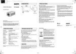
e_l5ax2_xe_7.fm Page 2 Monday, July 5, 2004 10:12 AM CONNECTIONS AND INSTALLATION ADJUSTMENTS AND SETTINGS AC 24 V connection CONNECTIONS GND AC24V CAMERA ADJUSTMENTS/SETTINGS DC 12 V connection GND AC24V 3 3 Monitor DC12V 1 VIDEO OUT POWER The camera comes pre-adjusted and ready to install at time of factory shipment, but you may want to make adjustments or settings to adapt to the operating conditions or installation environment. If you have trouble adjusting the camera, consult your dealer or an Authorized Sanyo Service Center. ( = Factory default setting) DC12V 2 2 CAMERA INSTALLATION Check that the polarity is correct. Change iris setting when using either lens below. Figure 2 EI CAMERA ADJUSTMENTS/SETTINGS Camera screws (Shorter) AI BLC HI CENT LL EI MULTI MANU Digital video recorder or time-lapse VCR L H : VIDEO IN : VIDEO OUT AI INT NORM OFF ATW Bracket screws (Longer) CONNECTIONS Q Q PHASE LEVEL Q The camera attachment bracket can be reconfigured as shown in Figure “ CAMERA INSTALLATION” above depending on the installation environment. As per design, use the removed screws. When using an RG-59U (3C-2V) cable, do not use it on piping or air wiring. Select the cable according to the distance between the devices you wish to connect. If you use a cable other than the types above, the image or sync signal will be attenuated and will not be transmitted correctly. Making connections 1 Connect the camera and peripheral equipment. 2 Connect the power cable. <When using an AC 24 V adapter> Connect 3 wire grounded cable (18AWG or higher) as shown in Figure 1. 3 Insert the power adapter plug into the wall outlet. NOTE on EI setting: If fluorescent lighting is used where the camera is installed, the object will flicker as a result. This type of phenomenon can be avoided by replacing the fluorescent lighting with incandescent lamps. If the light entering the lens exceeds the maximum required illumination, the image cannot be displayed properly. In that case, manually adjust the lens iris. HI Increased sensitivity allows shots to be taken in dark environments. NORM Normal setting NOTE: The HI setting causes noise generation and a grainy image. 3 BLC: Backlight compensation This camera has three different backlight compensation modes. Change the mode to match the backlight condition. Multi-spot metering, normal mode: When applying backlight compensation to the entire screen. Flange-back adjustment This normally does not need adjustment. If the picture is out of focus at the telephoto position, adjust the flange-back position as described below. Multi-spot metering, high mode: When applying more backlight compensation than normal mode. 1 Loosen the LOCK screw. 2 Set to the maximum telephoto position and focus the picture using the focus ring. Center-weighted metering mode: When applying backlight compensation to only the central portion of the screen. 3 Set to the maximum wide-angle position and focus the picture using the flange-back adjustment dial. Repeat steps 2 and 3 if the image does not stay in focus when changing from a wide-angle shot to a telephoto shot. 4 When the setting is complete, tighten LOCK <When using a DC 12 V adapter> Connect the cable as shown in Figure 2. Camera attachment bracket NOTE: When monitoring lighting or other extremely bright objects (which exceed the maximum required illumination), smearing may occur in the vertical or horizontal direction (either above and below the high-brightness object or as a perpendicular band). In such a case, adjust the angle of illumination and other factors while observing the monitor. When using the camera attachment stand (sold separately), select a location that will be able to withstand the weight of the camera and stand for many years, and fix them securely in place. Q When using an auto-iris lens. If the entire image is too dark or too bright, adjust the contrast using the LEVEL dial. • L (Counterclockwise): Closes the lens iris, making the entire image darker. • H (Clockwise): Opens the lens iris, making the entire image brighter. For adjusting the sensitivity of the camera. Use this setting for shooting in dark environments. What you need Supported coaxial cables (for indoor use) When using a manual or fixed iris lens and the electronic iris function is on. • Set the lens aperture to the shortest F stop. 2 Gain control CAMERA INSTALLATION Peripheral equipment (such as monitor, digital video recorder or timelapse VCR) Cables for connecting peripheral equipment and camera (coaxial cables, connecting plugs) Power adapter (AC 24 V or DC 12 V) You can use any of the following coaxial cables: RG-59U (3C-2V) Length: 250 m max. RG-6U (5C-2V) Length: 500 m max. RG-11U (7C-2V) Length: 600 m max. Q R WB B OFF Lets you fine-tune the white balance manually. MANU ATW WB • R (Red) dial : Turn clockwise to augment screen red. • B (Blue) dial : Turn clockwise to augment screen blue. Compensation is performed automatically. 5 Sync setting 1 Iris setting To prevent a fire hazard use any UL listed wire rated VW-1 for the AC 24 V input terminal. Figure 1 4 WB: White balance (color compensation) 3 This function is off. the LOCK screw. The POWER indicator (red) lights. NOTE on multi-spot metering: If the background of the object is extremely dark, set to “Center-weighted metering mode.” (Only when using an AC 24 V adapter) LL Line-Lock: Synchronizes the unit with power frequency when two or more cameras are connected via a switcher unit. When the image on the monitor rolls vertically, adjust the phase. • If using this unit as the second or subsequent camera; Adjust the roll by turning the PHASE dial. • If using this unit as the first camera; Adjust the roll using the phase adjuster on the second and subsequent cameras. INT Internal sync NOTE: When using a DC 12 V adapter, the sync setting is set to Internal sync.