1
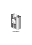
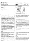
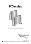
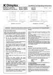
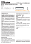
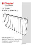
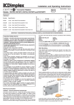
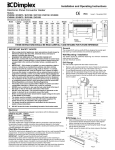
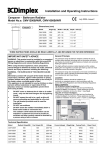
Installation and Operating Instructions
Dimplex Convector Heaters
INDCUK308R
Issue 6
Models : 3082S, 3087S, 3087ST, 3088T and 3088TA.
Dimensions
(millimetres)
450
MIN
Models
Specification
3082S
2.0kw
Heat Switch / Thermostat / Neon / 24hr Timer
3087S
3.0kw
Heat Switch / Thermostat / Neon / 24hr Timer
230
MIN
777 - 3.0kw
657 - 2.0kw
230
140
MIN
357
3087ST
3.0kw
On/Off Switch / Thermostat / Neon / 24hr Timer / Turbo
3088T
3.0kw
Heat Switch / Thermostat / Neon / Turbo
3088TA
3.0kw
Heat Switch / Thermostat / Neon / Turbo / Ioniser
432
230
MIN
Floor Mtd.
Wall Mtd.
THESE INSTRUCTIONS SHOULD BE READ CAREFULLY AND RETAINED FOR FUTURE REFERENCE.
IMPORTANT SAFETY ADVICE
Wall Mounting
WARNING – THIS APPLIANCE MUST NOT BE USED IN A
BATHROOM.
Three identical wall mounting brackets are secured to the base of the
heater with a fixing screw. To wall mount appliance, first remove the
brackets as follows :
Lay the heater on its back.
Following the sequence in Fig. 1 – identify and remove the fixing screw
securing the brackets located beside Mains Cable as shown in (a), then
pull out brackets and rotate them to disengage them from the slot (b).
Withdraw the brackets from the slot (c).
WARNING - DO NOT USE THIS HEATER IN THE IMMEDIATE
SURROUNDINGS OF A BATH, A SHOWER OR A SWIMMING POOL.
WARNING – THIS HEATER MUST NOT BE LOCATED IMMEDIATELY
BELOW A FIXED SOCKET OUTLET.
DO NOT USE THE HEATER UNTIL THE FEET OR WALL BRACKETS
ARE FITTED CORRECTLY.
FOLLOW these instructions carefully.
NEVER cover or obstruct in any way the heat outlet slots at the top
of the heater or the air inlet slots in the base of the heater.
The heater carries a warning ‘DO NOT COVER’ to alert the user to the
risk of fire that exists if the heater is accidentally covered.
Timer models 3082S, 3087S and 3087ST can be set to switch on
automatically. Remember to observe all safety warnings at all times.
If young children, the aged or infirm are likely to be left in the vicinity
of the heater, we advise that adequate precautions should be taken.
We recommend that a guard be fitted to ensure contact with the
heater is avoided and objects cannot be inserted into the product.
If the mains lead is damaged, it must be replaced by the
manufacturer or its service agent or a similarly qualified person in
order to avoid a hazard.
For further information, please contact our guard supplier direct on
Tel. No. 01603 667957, or in case of difficulty or for further advice
contact the Customer Helpline.
(a)
(b)
(c)
Fig. 1
Select a suitable position on a wall, near to a mains power socket,
making sure that there is at least 230 mm below the heater and at least
450 mm above the heater of unobstructed space. See also ‘Positioning
the heater’.
Fix the two top retaining brackets to the wall, using suitable fixings, for
2kw models at 358 mm centres and 3kw models at 478 mm centres –
see Fig 2.
Electrical connection
WARNING – THIS APPLIANCE MUST BE EARTHED
This heater must be used on an ~ supply only and the voltage marked on
the heater must correspond to the supply voltage. This heater is fitted with
a rewireable plug incorporating a 13 amp fuse. In the event of replacing
the fuse in the plug supplied, a 13 amp fuse approved by ASTA to BS
1362 must be used. If any other type of plug is used, a 15 amp fuse must
be fitted in the plug, the adaptor, or at the distribution board.
IMPORTANT : If the plug is not suitable for your socket, the 13 amp plug
should be removed. Before wiring the appropriate plug, please note that
the wires in this mains lead are coloured in accordance with the following
code :
GREEN AND YELLOW :
BLUE :
BROWN :
EARTH
NEUTRAL
LIVE
Connect the GREEN AND YELLOW wire to the terminal marked ‘E’ or by
, or coloured GREEN or GREEN AND YELLOW.
the earth symbol
Connect the BROWN wire to the terminal marked ‘L’ or coloured RED.
Connect the BLUE wire to the terminal marked ‘N’ or coloured BLACK
Fig. 2
Locate the heater on the top brackets and allow it to hang in place.
Fit the bottom bracket into the slot in the heater and then fix it to the wall.
Test that the heater is now securely fixed to the wall.
Positioning the heater
Heat Selector Switch
Always ensure that the heater is stood on a firm, level base near to, but
not directly beneath, a suitable mains supply socket.
Ensure that curtains and furniture are not positioned close to the chosen
position, as this would create a potential fire hazard.
We recommend that the heater should be wall-mounted in rooms where
children may be left unattended.
See also ‘Important Safety Advice’.
Free standing use
NEVER USE THE HEATER FREE STANDING WITHOUT THE FEET
FITTED.
Heat selection is available on all models as an economy feature.
On models 3082S and 3087S - the switch is a 2 position switch with two
possible heat settings as follows :
I
- The heater operates at half heat output.
II
- The heater operates at full heat output.
On models 3088T and 3088TA - the switch is a 4 position switch with an
Off position marked ‘O’ and 3 possible heat settings as follows :;
I
- The heater operates with 1kW output
II
- The heater operates with 2kW output
III
- The heater operates with full 3kW output
ON/OFF Switch
On model 3087ST – the switch operates as follows :
O
- The heater is off
I
- The heater operates with 2kW output
Lay the heater on its back,
and locate the foot fixing
screw (see a. in Fig. 3).
Remove the screw using
an X–head screwdriver,
then align foot over slots
and holes in base (see ‘b’
in Fig. 3) and push into
slots until the foot clips
into place.
Finally take the foot fixing
screw, insert and tighten
using a screwdriver to
secure the foot.
Note : The above description of the On/Off switch operation is with the
turbo neon switch in the off position – see also ‘Model 3087ST’ in the
‘Turbo Fan Models ..’ section.
Digital Timer Operation
IMPORTANT Remember to observe all safety warnings when operating
the heater on auto setting unattended or attended .
Fig. 3
NOTE – The wall mounting brackets indicated in Fig. 3 can be left secured
to the base if they are not required.
Using the heater
Plug in and switch on at the wall socket.
The timer allows you to select ‘MANUAL ON’ , ‘AUTO’ or’ MANUAL
OFF’ operation mode by pressing the ‘MODE’ (Input/Output) button until
the required mode appears at the bottom of the timer display.
‘MANUAL ON’ mode allows power to the heater uninterrupted by the
timer settings. The heat selector switch will control the output (see ‘Using
the heater’).
‘AUTO’ mode allows the convector to switch ON and OFF according to
the timer settings (see ‘Setting Programs’ section below).
‘MANUAL OFF’ mode switches off all heater operation completely.
On models 3082S & 3087S the timer clock will operate all the time that
the heater is connected to the mains supply, regardless of the setting of
the heat selector switch. Set the timer control switch as required for OFF,
Manual or Automatic
operation – see ‘Timer Operation’.
12/24 Hour Mode Either 12 or 24 hour modes can be used.
Press the S (Set) and PROG (Program) buttons simultaneously to switch
between 12 and 24 Hour mode.
The heat output is controlled by the
thermostat - see ‘Thermostat’
For initial use, plug the heater into a regular household power point and
turn the power on.
The ‘Power On’ neon will only light, when the heater is connected to the
power supply and the timer is in either ‘MANUAL ON’ or ‘AUTO’ On
mode.
Clear all current information by pressing the R button with a pointed
object such as a pencil. Note: Do not use a needle or pin.
The timer is now ready to be set up for use.
Please note – the element has been
coated with a protective film which will
burn off during the first few minutes of
use and may cause a small amount of
fuming. This is quite normal – the fumes
are non-toxic and will quickly disappear.
We recommend that you open a
window to ventilate the room when
using the heater for the first time.
Initial Operation
Fig. 4
(Model 3082S , 3087S
control shown)
Controls
Thermostat
The thermostat controls the heat output according to the room
temperature.
This ensures that the heater will not produce heat unnecessarily when the
room is warm.
To set the temperature you require, turn the thermostat knob clockwise
until the desired temperature is reached. Alternatively to heat a cold room
quickly, turn the thermostat knob up fully.
When the room has reached the desired temperature, turn the thermostat
knob anti-clockwise until the thermostat just clicks off.
The heater will now automatically operate at this temperature.
The thermostat also has a frost protection setting marked ‘∗’. This setting
is useful in areas such as garages to prevent frost damage. If the
thermostat is set to its minimum setting '∗', the heater will cycle ON and
OFF to maintain a temperature of approximately 5°C to help protect
against frosty conditions.
Fig. 5
Setting Current Time
1.
2.
3.
Press the S (Set) button and keep pressed while pressing the D
(Day) button until the actual day is displayed. Continue by pressing
H (Hour) or M (Minute) button until the current hour or minute is
displayed. When resetting, the buttons D, H or M can be held down
for rapid forward counting.
Release both buttons. The day and time will now be set.
To reset incorrect time, repeat previous steps.
Summertime Function
Summertime function is very useful for areas with summertime system ,
the timer can quickly & easily be changed to operate in SUMMER time
mode i.e. one hour ahead , and back again as follows ;
1.
2.
Press the S (Set) and MODE (Input/Output) buttons simultaneously.
The LCD will show ‘SUMMER’. The clock will switch ahead one hour.
Press the buttons together again and the clock will switch back again
one hour to standard time & ‘SUMMER’ will no longer be displayed .
Turbo Fan models
(3087ST, 3088T & 3088TA)
Setting Programs
Once the correct time is set , a total of 8 ON/OFF time programs can be
set for AUTO operation. These can be set to operate on any of 16
different combinations of individual days or groups of days depending on
your individual choice. To program the timer follow the setting instructions;
1.
2.
To select the first of your 8 ON/OFF programs simply press the
PROG (Program) button once , the program is then input as follows ;
You first select one of the 16 different combinations of individual days
or groups of days you wish to set this program for. Continue to press
and release the D (Day) button to go through the choices until the
day or blocks of days you require appears along the top of the timer
display then stop pressing , the 16 different combinations that can be
chosen are as follow ;
1)
2)
3)
4)
5)
6)
7)
8)
3.
4.
5.
6.
Mo
Tu
We
Th
Fr
Sa
Su
Mo, Tu, We, Th, Fr, Sa, Su
9)
10)
11)
12)
13)
14)
15)
16)
Mo, Tu, We, Th, Fr
Sa, Su
Mo, Tu, We, Th, Fr, Sa
Mo, We Fri
Tu, Th, Sa
Mo, Tu, We
Th, Fri, Sa
Mo, We Fr, Su
Now set the time by pressing the H (Hour) button and then M
(Minute) button until the desired time setting is displayed.
Press the PROG (Program) button again to finish the first ON setting
and enter into the first OFF setting. By repeating steps ‘2’ & ‘3’ above
you can now complete the input of the first OFF setting.
Press the PROG (Program) button again to finish the first ON/OFF
nd
program and enter into the 2 ON setting. Repeat steps ‘2’ , ‘3’ and
‘4’ to complete this program , then press P again and repeat cycle as
necessary.
Once you have completed the number of ON/OFF programs you
require (up to a maximum of 8) , press the S (Set) button to save the
settings and the timer is now ready to operate in Auto mode .
EXAMPLE : To set Timer ON at 18:15 and Timer OFF at 22:15 everyday
a)
b)
c)
d)
e)
f)
g)
Once the timer batteries are fully charged , if there is either a power cut
or if the heater is disconnected from the mains for less than 100 hours ,
then the timer will continue to keep time & the settings in the memory will
remain intact .
If however the timer back up batteries have not been charged fully , or if
the heater is deprived of power for longer than 100 hours , then the time
and the programme settings are likely to be lost and you may therefore
need to reset the time and the programme before using in ‘Auto’ mode
again.
Press PROG and LCD displays
‘1_ON’
Press D until LCD displays
‘MO, TU, WE, TH, FR, SA, SU’
Press H until LCD displays
‘6:00PM’ or ’18:00’
Press M until LCD displays
‘6:15PM’ or ’18:15’
Press PROG and LCD displays
‘1_OFF’
Repeat c) and d) until LCD displays
‘10:15PM or 22:15’
Press S and the program is saved and the current time display
returns.
TIP : When verifying your programs ensure that the settings do not
overlap, especially when using the block option.
The turbo fan can be used to circulate
the heat around the room to help it
reach the desired temperature more
quickly.
On all turbo models with the heat
selector switch at max. setting (3kw
operation) the fan automatically
switches on to override the operation
of the Turbo On/Off neon switch. This
permanent operation of the fan at
maximum heat setting ensures more
efficient operation and heat circulation
around the room
Model 3088T & 3088TA
On these models you can choose to
Fig. 6
use the fan to help circulate the heat
Turbo Models
at lower heat settings by switching the
Turbo switch on with the heat selection
switch at setting I or II .
In warm weather you can also use the fan on these models to circulate
cool air as follows: Set the heat selector switch to it's off position - 'O' ,
set the Turbo switch to it's on position and set the thermostat to it's
maximum setting by turning the thermostat knob fully clockwise.
Model 3087ST
On this model with the I / II switch at position I and the turbo switch in it’s
Off position ( neon off ) there is no heat output from the convector. With
the I / II switch still in the I position you can have 1kw output but only with
the turbo boost on, also by switching the turbo switch to it’s On position
(neon on). To get an output of 2kW leave the turbo switch off and set the
I / II switch to position II. (Note 2kw is only possible with turbo off). To
achieve 3kw output now turn on the turbo switch which will combine the
2kW setting with a 1kW fan boost setting to give the total output of 3kw
with fan boost.
Note there is no cold blow operation on this model and that all heat
settings operate under the control of the thermostat.
Note that on all models the fan and the neon on the Turbo switch will
cycle on and off under the control of the thermostat – see ‘Thermostat’.
Ioniser Model 3088TA
The ioniser operates all the time that the heater is connected to the
mains supply.
Principles of ionisation :
•
TIP : To clear a section in a Program, press the C (Clear) button. To
reactivate this section press the C button again.
Notes on switching between Manual ON/Auto/Manual OFF
1.
2.
3.
4.
Pressing MODE (Input/Output) button allows you to change between
Manual ON / Auto / Manual OFF modes , current mode will be
displayed on the bottom of the LCD display.
In Manual ON or Manual OFF mode, the Timer operates but the
programme settings are inactive.
When the mode is turned from Manual ON to Auto, the Timer mode
will remain ON until the next programmed timer off setting is reached.
When the mode is turned from Manual OFF to Auto the timer mode
will remain OFF until the next programmed timer ON setting is
reached.
Note - Timer Memory Back Up Batteries
Once the heater has been left plugged in with the socket switched on for
at least 12 hours the timers memory back up batteries will be fully
charged.
•
•
•
Restores the natural balance of the air.
The physiological and psychological effects of negative ions are well
known, including increased alertness, easier breathing and better
sleep.
In addition to the direct benefits, the stream of negative ions will
charge dust, pollen, bacteria and smoke particles. These charged
particles are then attracted to the surfaces in the room and
deposited as fine dust, leaving the air cleaner, fresher and healthier.
The output from the ioniser will be combined with the output of the
heater, with or without fan boost. The fan increases the volume of
air affected by the ioniser, enhancing its range and increasing the
amount of pollutants from the air.
In warm weather, the ionised air can be circulated by using the
turbo fan only – see ‘Turbo fan models’.
Safety – overheat protection
Cleaning and User Maintenance
For your safety, this appliance is fitted with a thermal cut-out. In the event
that the product overheats, the cut-out switches the heater off
automatically.
To bring the heater back into operation, remove the cause of the
overheating, then unplug or turn off the electrical supply to the heater for a
few minutes.
When the heater has cooled sufficiently, re-connect and switch on the
heater.
WARNING – ALWAYS DISCONNECT FROM THE POWER SUPPLY
BEFORE CLEANING THE HEATER.
Do not use detergents, abrasive cleaning powder or polish of any kind on
the body of the heater.
Allow the heater to cool, then wipe with a dry cloth to remove dust and a
damp cloth (not wet) to clean off stains. Be careful not to allow moisture
into the heater.
Important Notes
After Sales Service
Although this heater is manufactured to comply with the relevant safety
standards, certain types of carpets could become discoloured by the
temperatures under a portable heater. If you are concerned about this, we
recommend that you contact the carpet manufacturer for guidance.
Alternatively, either stand the heater on a suitable base to shield the
carpet or wall-mount it – call our Helpline for further advice.
You may notice some parts of the element appearing to be hotter from
time to time because of the variable airflow through the heater. This does
not cause a safety hazard.
Your appliance is guaranteed for three years from the date of purchase.
We undertake to repair or exchange free of charge within this period, any
part found to be defective due to a manufacturing fault.
Your rights under this guarantee are additional to your statutory rights,
which in turn are not affected by this guarantee.
Please retain your receipt as proof of purchase.
The heat outlet grille may become discoloured with use – this is caused by
airborne pollution and is not a fault.
The product complies with the European Safety Standards EN60335-2-30 and the European Standard Electromagnetic Compatibility
(EMC) EN55014, EN60555-2 and EN60555-3 which cover the essential requirements of EEC Directives 73/23 and 89/336
Glen Dimplex UK Limited
Millbrook House
Grange Drive
Hedge End
Southampton
Hampshire. SO30 2DF
UK customer help line (8.00AM – 6.00PM Mon-Fri; 8.30AM-1.00PM Sat)
Customer Services:
Republic of Ireland
Tel. 0870 7270101
Fax. 0870 7270102
e-mail [email protected]
Tel. 01 8424833
[c] Glen Dimplex UK Limited
All rights reserved. Material contained in this publication may not be reproduced in whole or in part, without prior permission in writing of Glen Dimplex UK Limited.