1
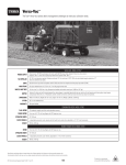
Topper-Inst-Mono10
24/2/10
16:06
Page 1
Product No’s 16150
Operating Instructions
16165
16174
Customer service
Tel:
01522 507550
Fax:
01522 689011
E-mail: [email protected]
Topper-Inst-Mono10
24/2/10
16:06
Page 2
Spaldings Limited Customer service Tel: 01522 507550 Fax: 01522 689011
Topper-Inst-Mono10
24/2/10
16:06
Page 3
Section
CONTENTS
1
1
INTRODUCTION
INTRODUCTION
1.0 Identification . . . . . . . . . . . . . . . . . . . . . . . . . . . . . . . 1
1.1 Before operation . . . . . . . . . . . . . . . . . . . . . . . . . . . . 1
1.0 Identification
2
SAFETY GUIDELINES
2.0 Symbols . . . . . . . . . . . . . . . . . . . . . . . . . . . . . . . . . . 2
2.1 Understanding the safety symbols . . . . . . . . . . . . . . 2
2.2 General safety instructions . . . . . . . . . . . . . . . . . . . . 3
2.3 Operator requirements . . . . . . . . . . . . . . . . . . . . . . . 3
3
INSTRUCTIONS FOR USE
3.0 Headstock positioning . . . . . . . . . . . . . . . . . . . . . . . 4
3.1 Connection to a tractor . . . . . . . . . . . . . . . . . . . . . . . 4
3.2 Working height. . . . . . . . . . . . . . . . . . . . . . . . . . . . . . 5
3.3 Hydraulics . . . . . . . . . . . . . . . . . . . . . . . . . . . . . . . . . 5
3.4 In the field . . . . . . . . . . . . . . . . . . . . . . . . . . . . . . . . . 5
3.5 Road transport . . . . . . . . . . . . . . . . . . . . . . . . . . . . . . 5
•
•
•
•
•
•
•
4
MAINTENANCE
4.0 Lubrication . . . . . . . . . . . . . . . . . . . . . . . . . . . . . . . . 6
4.1 Belts adjustment . . . . . . . . . . . . . . . . . . . . . . . . . . . . 6
4.2 Blades adjustment . . . . . . . . . . . . . . . . . . . . . . . . . . 6
4.3 Replacement of front stone guards . . . . . . . . . . . . . 6
4.4 Storage and post-season . . . . . . . . . . . . . . . . . . . . . 6
5
SPECIFICATION & SPARE PARTS
5.0 Specification . . . . . . . . . . . . . . . . . . . . . . . . . . . . . . . 7
5.1 Replacement parts to fit 2.8m & 2.2m Toppers. . . . . 7
5.2 Replacement parts to fit 1.95m offset Topper . . . . . . 8
5.3 Replacement parts to fit 1.65m compact Topper . . . 8
5.4 Replacement flails . . . . . . . . . . . . . . . . . . . . . . . . . . . 8
The identification plate (Fig. 1), attached to the machine shows
the following information:
Manufacturer’s Name
CE mark
Year of production
Serial number
Recommended tractor horsepower
Overall weight
PTO speed and direction of rotation
NOTE: It is important to refer to the data on the identification plate
in order to check the compatibility of the topper with the tractor to
be used and when ordering spare parts.
Fig.1 Identification plate
1.1 Before operation
At the factory each machine is carefully inspected to guarantee
proper functioning. Each machine has a pre-delivery
inspection.
e-mail: [email protected] visit: www.spaldings.co.uk
1
Topper-Inst-Mono10
Section
24/2/10
16:06
Page 4
2
SAFETY GUIDELINES
2.0 Safety symbols
2.1 Understanding the safety symbols
The operator must fully understand the warning symbols on the
machine.
Before operating the machine, it is important that each
operator understands the following explanations.
The symbols are used to highlight important information:
Safety symbol
Symbol meaning
BEFORE OPERATION
DANGER
To draw the operator’s attention to situations which
could endanger his or other peoples safety.
CAUTION
To draw the operator’s attention to situations which
could affect the machine performance but not his or
other peoples safety.
1.
2.
IMPORTANT
To draw the operator’s attention to situations which do
not affect the machine performance and his or other
peoples safety.
1 & 2. Before operating, adjusting or
servicing the machine, it is important
that each operator carefully reads the
operating instructions.
Servicing etc. should be carried out
with the engine stopped, hand brake
applied and the starter key removed.
DURING OPERATION
3. Danger from flying objects.
Any persons near the machine must
keep at a safe distance.
It is important to comply with the instructions given by the safety
stickers, which must always be on the machine. If new stickers are
required, contact Spaldings.
3.
4 & 5. Danger of hand injury.
Keep away from rotating parts and
the PTO shaft.
Do not attempt to remove safety
guards or make adjustments whilst
the machine is working or the
tractor engine running.
The manufacturer is not responsible for any consequence due
to the inobservance of these instructions.
4.
6.
5.
7.
6. Danger of feet injury. Any persons
near the machine when working,
must keep at a safe distance.
7. Danger of hand injury. Any person
near the machine when working,
must keep at a safe distance.
Do not attempt to remove safety
guards or make adjustments whilst
the machine is working or the tractor
engine running.
SERVICING
8.
8. Servicing, lubrication etc. should
be carried out with the engine
stopped, the hand brake applied
and the starter key removed.
Once the machine is raised do not
work underneath it without secure
support.
LIFTING
9. When lifting the machine always
use appropriate lifting gear attached
to the lifting eyes on the machine
frame.
9.
2
Spaldings Limited Customer service Tel: 01522 507550 Fax: 01522 689011
Topper-Inst-Mono10
Section
24/2/10
16:06
Page 5
2
SAFETY GUIDELINES
2.2 General safety instructions
2.3 Operator requirements
• During operation keep a safe distance from rotating parts and
the PTO shaft.
• Do not remove safety guards during operation or with the
tractor engine running.
• Servicing, lubrication etc. should be carried out with the engine
stopped, the hand brake applied and the starter key removed.
• Once the machine is raised do not work underneath it unless
supported securely.
• Whilst at work ensure any persons or animals nearby are a safe
distance from the Topper to avoid injury caused by flying
objects.
• When lifting the machine always use appropriate lifting gear
attached to the lifting eyes on the machine frame.
• The operator must understand how the machine works, be
responsible when operating the machine and aware of
potential danger.
• The operator must have read this booklet and fully understand
the warning symbols on the machine.
• The operator must be adequately trained and qualified to
operate the tractor and the implements attached to it.
e-mail: [email protected] visit: www.spaldings.co.uk
3
Topper-Inst-Mono10
Section
24/2/10
16:06
Page 6
3
INSTRUCTIONS FOR USE
3.0 Headstock positioning
3.1 Connection to a tractor
SIDE POSITIONING
LINKAGE
1.65m Model
It is possible to fit the headstock in a central position or shifted to
one side by 15cm. To change the position of the headstock:
Some Topper models have adjustable lower link brackets. Before
attaching the machine to the tractor, adjust the brackets to match
the distance between the tractor arms.
1. Remove the bolts connecting the headstock to the chassis and
reposition it using the next series of holes on the chassis.
2. Refit the ‘H’ shaped plates so that they blank the holes on the
chassis to avoid material escaping through the holes.
1. On a flat surface, reverse the tractor to the machine, apply the
hand brake, attach the lower links and then the top link.
2. Adjust tension chains or links in order to allow only a minimum
sideways movement, adjust the top link so that when in
operation the machine is parallel to the ground.
3. Fit all locking pins.
Model AT
When this model is not fitted with the optional hydraulic side shift,
it is possible to manually move the headstock to the desired
position:
1. Slacken the bolts that lock the sliding tube to the galvanised
tube.
2. Remove the two bolts fixing the top stay to the guide on top of
the chassis and reposition the headstock.
3. Re-fit and secure the bolts.
Models GT, LT
When these models are not fitted with the optional hydraulic side
shift, it is possible to manually move the headstock to the desired
position:
FITTING THE PTO SHAFT
IMPORTANT: Please ensure that the PTO power shaft is cut to
the correct length to suit the tractor which the Topper is
attached – for further information see the instruction booklet
attached to the power shaft.
BOTH SECTIONS OF THE POWER SHAFT MUST BE CUT TO
THE EXACT SAME LENGTH.
4. Check that the guards chains are properly secured.
1. Slacken the bolts that lock the sliding brackets to the
galvanised tube and reposition the headstock.
2. Secure the bolts.
4
Spaldings Limited Customer service Tel: 01522 507550 Fax: 01522 689011
Topper-Inst-Mono10
Section
24/2/10
16:06
Page 7
3
INSTRUCTIONS FOR USE
3.2 Working height
3.3 Hydraulics
The working depth is controlled by re-positioning the skids or the
rear wheels (where applicable).
When the machine is fitted with hydraulic side shift, connect the
hoses to the tractor double-acting spool valve.
SKID ADJUSTMENT
The hydraulic side shift should never be operated with the
machine standing on the ground
1. Slacken the front bolt A (Fig. 2)
2. Remove the rear bolt B
3. Adjust the skid to the required position
4. Re-fit the rear bolt. Re-tighten front bolt.
Repeat the operation on the other side of the machine.
DO NOT SET THE MACHINE TOO LOW.
BLADES TOUCHING THE GROUND ARE DANGEROUS AND
CAN DAMAGE THE ROTOR.
3.4 In the field
Lower the Topper to the ground, engage the PTO and increase
the speed. Start to move forward at an adequate speed.
3.5 Road transport
If the machine is fitted with rear wheels, these must be folded by
relocating the pin.
A
B
Fig. 2 Skid adjustment
REAR WHEELS ADJUSTMENT
(OPTIONAL EXTRA)
With the wheels in the working position.
1. Slacken the bolt A (Fig.3) to adjust the distance
between the wheels.
2. Remove and reposition bolt B to achieve the
required depth.
Repeat the operation on the other side.
B
A
Fig. 3 Rear wheel adjustment
e-mail: [email protected] visit: www.spaldings.co.uk
5
Topper-Inst-Mono10
24/2/10
16:06
Page 8
4
Section
MAINTENANCE
TENSIONING BELTS
BEFORE CARRYING OUT ANY SERVICING TURN OFF
THE TRACTOR ENGINE, APPLY THE HAND BRAKE AND
DISENGAGE THE PTO. WHEN WORKING BENEATH THE
MACHINE ENSURE IT IS ADEQUATELY SUPPORTED.
Model XT
The correct belts tension is obtained by adjusting the tensioner
placed inside the transmission case.
4.0 Lubrication
Every 10 working hours:
1. Grease the rotor’s supports and the rear roller supports (when
fitted) with lithium grease through the grease nipples located
on the side of the machine.
Every 50 working hours:
1. On those models fitted with side shift, grease all sliding parts
using lithium grease.
2. Check the gear box oil level. If necessary, top up using gear oil
EP90, the oil level plug is fitted halfway up the gearbox casing
and placed on the side or front of the gearbox depending on
the model.
Every 250 working hours / or once a year:
1. Change the gear box oil.
1. Slacken the counter nut A (Fig. 6) and turn the bolt B until the
right tension is obtained. This can be checked through the slot
placed on the opposite side of the transmission case. The belts
must not have a free movement of more than 5mm.
2. Secure the counter nut A.
4.2 Blades replacement
1. Everyday check the bolts for tightness and the blades for wear
and breakages (Fig. 7).
2. Replace all broken, bent or worn blades. To keep the rotor
balanced, cut or grind the new blade so that it weighs as the
other blades.
3. Depending on the model, blades can be reached from the back
once the tailgate has been lifted or from underneath by lifting
the machine.
4.1 Belts adjustment
After the first 2/3 hours of work and every 40 thereafter check the
belts tension. Through the slot on the belt guard, check that the
belts do not give more than 5mm.
TENSIONING BELTS
Models AT, GT, HT & LT, MT, KT, ST
1. Slacken the bolts under the gearbox (models AT, GT, HT) or
next to the gearbox (models LT, MT, KT, ST) and those holding
the side shaft plate located on the side of the machine.
2. To obtain the right tension adjust the screw A (Figs. 4, 5) in
order to move the whole transmission parallel.
Fig. 7 Blade replacement
4.3 Replacement of front stone guards
A
If the front stone guards are damaged, they must be immediately
replaced.
A
1. Remove the bolt securing the pivot rod and slide it out until the
damaged guard can be replaced.
2. Push the rod back in and fix it.
Figs. 4 & 5 Belts adjustment
4.4 Storage and post-season
Before storing the machine for short or long term periods:
A
B
Fig. 6 Belts adjustment
6
1. Clean the machine.
2. Inspect it for damaged or broken parts and replace them as
necessary.
3. Spray with a rust inhibitor all parts that during use have lost their
initial paint (Agri-wax, 5 ltrs, prod. 04442).
4. Grease the PTO shaft following the manufacturer
recommendations.
5. Store the machine in a dry place.
Spaldings Limited For replacement parts, Tel: 01522 507600 Freefax: 0800 716040
Topper-Inst-Mono10
Section
24/2/10
16:06
Page 9
5
SPECIFICATION & REPLACEMENT PARTS
5.0 Specification
Spaldings
prod no.
Working
width
Dimensions
Weight
Rotor
diameter
PTO
speed
Power
requirement
Flails
prod no.
No. of
Flails
940kg
200 x 10mm
540 rpm
80 – 110 hp
08493
26
550kg
150 x 10mm
540 rpm
60 – 80 hp
16166
28
540 rpm
25 – 35 hp
16166
26
REAR MOUNTED FLAIL TOPPERS
16150
2.8m
295 x 130 x 95cm
OFFSET REAR MOUNTED FLAIL TOPPER
16165
1.95m
208 x 124 x 162cm
COMPACT REAR MOUNTED FLAIL TOPPER category 1 linkage
16174
1.65m
180 x 80 x 70cm
230kg
108 x 8mm
5.1 Replacement parts
TO FIT 2.8 & 2.2m REAR MOUNTED TOPPERS (Fig.8)
16175
16176
16131
16142
16148
16182
16133
16212
16117
16118
16119
16122
16121
Cat.2 Lower link pin.
Cat.2 Top link pin.
Transmission V-belt (4 required).
Drive shaft oil seal.
Drive belt guard.
Rear roller (2.8m).
Roller bearing.
Main rotor bearing.
Skid R.H.
Skid L.H.
Bolt-on skid wear plate (fits 16117 & 16118).
Bolt and lock nut, c/sunk hex key fitting, for 16119. Pk of 10.
Front metal stoneguard.
16147
16141
16143
16140
16189
16145
16146
16147
16132
16162
16163
Complete gearbox.
Gearbox input shaft.
Complete PTO shaft.
Side shift tube (post July 2007).
Side shift tube, 2-hole fixing (pre-2007).
Side shift hydraulic ram.
Headstock swan neck.
Side shift bearing.
Enamel paint, Spaldings Topper red, 5 litres.
Aerosol enamel paint, Spaldings Topper red, 400 ml.
16132
16141
16148
16142
16146
16131
16189
16117
16118
16140
16143
16121
16122
16119
16133
Fig. 8
e-mail: [email protected] visit: www.spaldings.co.uk
7
Topper-Inst-Mono10
Section
24/2/10
16:06
Page 10
5
SPECIFICATION & REPLACEMENT PARTS
5.2 Replacement parts
5.4 Replacement flails
TO FIT 1.95M OFFSET TOPPER (Fig. 9)
TO FIT 2.8 & 2.2m REAR MOUNTED TOPPERS (Fig. 10)
16164
16169
16171
16121
08493
16144
16134
PTO Power shaft and guard.
Drive belt (4 required).
Bearing for roller.
Front metal stoneguard.
Heavy duty forged flail. 16.5mm Φ.
Spacer (2 per flail), pack of 10.
M16 x 110mm 10.9G bolt & lock nut. Pack of 10.
16134
16144
16164
08493
Flails per machine:
2.8m – 26, 2.2m – 20
Fig. 10
Fig. 9
TO FIT 2.8 & 2.2m REAR MOUNTED TOPPERS (Fig. 11)
5.3 Replacement parts
TO FIT 1.65M COMPACT TOPPER
16183
16177
16178
16179
16194
16180
Rotor c/w flails (1.65m).
Drive belt (2 required).
Complete PTO shaft.
Front metal stoneguard.
Rear roller.
Roller bearing.
16136
16135
16137
16134
Heavy duty grass flail.
Bush for 16136.
Spacer for 16135.
M16 x 110mm 10.9G bolt & lock nut. Pack of 10.
16134
16137
16135
Flails per machine:
2.8m – 26 sets of 3 (78)
2.2m – 20 sets of 3 (60)
16136
Fig. 11
TO FIT 1.95m OFFSET & 1.65m COMPACT TOPPERS (Fig.12)
16166
16167
16168
Heavy duty forged flail. 14.5mm Φ
M14 x 90mm 10.9G bolt & lock nut. Pack of 10.
Spacer (2 per flail). Pack of 10.
16167
16168
16166
Flails per machine:
1.95m – 28, 1.65m – 26
Fig. 12
8
Spaldings Limited For replacement parts, Tel: 01522 507600 Freefax: 0800 716040
Topper-Inst-Mono10
24/2/10
16:06
Page 11
e-mail: [email protected] visit: www.spaldings.co.uk
24/2/10
16:06
Page 12
www.spaldings.co.uk
Spaldings Limited, Sadler Road, Lincoln LN6 3XJ
Tel: 01522 507550 • Fax: 01522 689011
Spaldings (Ireland) Limited, Moydrum Business Park, Athlone, Co. Westmeath
Tel: 090 6486008 • Fax: 090 6486133
Flail topper Inst: 02.2010
Topper-Inst-Mono10