1
Micro Double Valve Pump Operating Instructions
Model 408M Micro DVP
Operating Principles
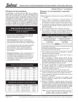
When the Solinst Micro Double Valve Pump (DVP) is placed in a well or
borehole, water rises inside the pump and up the concentric tubes to static
level. A Control Unit is used to supply compressed gas or air to the pump
on the drive cycle. The gas pushes down on the water column contained in
the outer, 3/8” dia. tubing (drive line), closing the check valve at the base of
the pump. This forces the water up the inner 3/16” dia. sample line tubing.
A vent cycle, during which the gas is released, allows water to refill the pump
and drive line (outer tubing). The top check valve prevents water in the
sample line from falling back into the pump body. This drive and vent cycle
is repeated manually or automatically as set by the timers on the control unit.
The cycle may be regulated for purging or sampling.
3/16” Teflon Sample Line
Sample Discharge
Pump Head Manifold
Sample
Stem
Drive Gas
Entry
Note: The pump has been cleaned before leaving Solinst, however, if you wish
to decontaminate your pump before use, follow the decontamination
procedure overleaf.
Purging/Sampling Setup
1. When using the Solinst Model 466 Electronic Control Unit, connect the "Air
Out" line to the quick connect fitting on the side of the Delrin pump head
manifold.
3/8” Teflon
Pump Body
2. This feeds air or nitrogen to the drive line, which is the larger diameter tubing.
3. The smaller inner tube is the sample line.
Taking a Sample with the Micro Double Valve Pump
3/8” Teflon or
LDPE Tubing
1. Prior to installing 408M take a Water Level measurement using an accurate
Water Level Meter such as the Solinst Model 101 to determine the height
of water above the pump intake. A minimum of 10 ft. is recommended.
2. Insert your sample line at surface into your sample container.
Needle Valve
Note: Please refer to the 466 Electronic Control Unit Operation Instructions
for proper setup and operation using a compressed gas source.
3. Adjust the control unit “Pressure Regulator” to the appropriate value [(pump
intake depth below grade in feet x 0.43) +10 psi].
4. Adjust the Drive and Vent times on the Model 466 Electronic Control Unit
to adjust the sampling flow rate to the desired amount.
Stainless Steel
Check Ball
5. During the Drive period on the Control Unit, the sample line will produce
your water sample. During the Vent period on the Control Unit, the Drive
Line is filling again under hydrostatic pressure.
6. For Double Valve Pump Optimization, select the desired flow rate from
the pre-set screens. Use the Flow Regulator to adjust flow to your desired
rate. If a higher flow is required, slowly increase the Drive time to increase
the flow rate. If air is expelled, decrease the Drive time. To further optimize
the flow rate, increase or decrease the Vent time until the highest flow rate
is achieved.
7. Once optimum flow rates have been achieved, make note of the pressure,
flow rate and timer settings for subsequent sampling dates. For example,
with an 85 ft. - 408M assembly and a static water level at 60 ft. With a
pump pressure of [(85 ft. x 0.43) + 10psi] = 50psi., a suitable drive of 11 sec.
and vent of 9 sec., will produce a flow rate of about 150mL/min.
Removable
50/100 Mesh
Intake Filter
Actual Size
Complete Assembly
with Manifold
High Quality Groundwater and Surface Water Instrumentation
Decontamination Suggestions
1. Disassembling your Model 408M Micro Double Valve Pump
is not recommended.
2. Following your usual cleaning protocols, we suggest washing
the exterior of the pump assembly with a suitable cleaning
solution (ie. soap, mild solvent).
466 Electronic Control Unit
(160 & 250 psi)
Air In
Drive
Line
3. The pump's interior can be cleaned by flushing or pushing
your cleaning solution up and through the pump's intake.
You have a couple of options to achieve interior flushing.
4. With the filter unscrewed and off the pump's intake, push a
clean piece of 5/8" X 3/8" silicon (or equivalent) tubing over
the 3/8" OD SS pump intake. Alternatively, you can use a
1/4" push fitting (1/4" X 10-32 UNF) which can be directly
threaded into the pump's intake. Then push a suitable length
of 1/4" tubing into this fitting. With either option, connect
the other end of the tubing to a peristaltic pump and push
your cleaning solution through the pump's interior.
Sample Line
Optional Multi-Purge Manifold Assembly
To purge and sample up to 7 Micro Double Valve Pumps, at a
single location, a Multi-Purge Manifold Assembly is available.
1. Mount the Multi-Purge Manifold over the well installation,
after obtaining water level measurements.
2. Thread the pumps down through the collar opening in the
Multi-Purge Manifold below the head assembly.
Sample
Bottle
466 12 Volt Compressor
3. Connect each individual pump manifold to the appropriately numbered Multi-Purge Manifold connection by pushing
the male LL10 connector (on the pump manifold) into the
brass quick connect fitting (on the assembly) while pulling
back the brass sleeve on the fitting.
4. Connect the compressed gas source/controller to the Multi-Purge
connection at the top of the head assembly, using the same
method as describe in step 3.
Filter
408M Micro
Double Valve
Pump
5. Open and adjust valves on the head assembly of the Multi-Purge
Manifold for those pumps that require purging/sampling.
Operate control box according to the instructions provided.
Typical Sampling Setup
Note: Minimum input pressure to
466 Electronic Control Unit is 100 psi
Top and Side View of Multi-Purge Manifold
with 4 Pumps Connected.
Printed in Canada
01/2005
For further information contact: Solinst Canada Ltd.
Fax: +1 (905) 873-1992; (800) 516-9081 Tel: +1 (905) 873-2255; (800) 661-2023
35 Todd Road, Georgetown, Ontario Canada L7G 4R8
Web Site: www.solinst.com E-mail: [email protected]