1
Table of Contents
1
2
3
4
General Information .................................................................................................................... 3
Components and Materials of Construction ............................................................................. 3
Regulations and Safety Instructions ......................................................................................... 3
Application and Planning ........................................................................................................... 4
4.1
4.2
4.3
5
Application .................................................................................................................................................4
MVHR operation overview.........................................................................................................................4
MVHR installation planning .......................................................................................................................4
Installation ................................................................................................................................... 5
5.1
General information ...................................................................................................................................5
5.2
Impact noise reduction ..............................................................................................................................5
5.3
Wall mounting the MVHR ..........................................................................................................................5
5.4
Heat exchanger retaining bracket .............................................................................................................5
5.5
Ducting ......................................................................................................................................................6
5.5.1
Duct connections................................................................................................................................6
5.5.2
Left-handed installation duct connections (viewed from the top of the MVHR) .................................7
5.6
Condensate drain ......................................................................................................................................7
5.7
Typical installation example ......................................................................................................................7
5.8
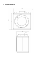
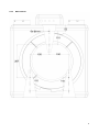
Installation dimensions ..............................................................................................................................8
5.8.1
MVHR unit ..........................................................................................................................................8
5.8.2
Wall brackets......................................................................................................................................9
6
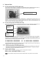
Technical Data........................................................................................................................... 10
6.1
Air flow settings (Xcell 200 QV model only) ........................................................................................... 10
6.2
Air flow settings (Xcell 200 QVW model only) ........................................................................................ 10
6.2.1
PCB Port pins (Xcell 200 QVW model only): .................................................................................. 10
6.3
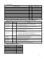
Factory speed settings: .......................................................................................................................... 10
6.4
Technical data: ....................................................................................................................................... 11
6.5
Applied Energy accessories for manual or automatic MVHR operation: ............................................... 11
6.6
Applied Energy MVHR spares: .............................................................................................................. 11
7
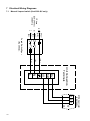
Electrical Wiring Diagrams ....................................................................................................... 12
7.1
7.2
7.3
7.4
7.5
8
Controller Functions ................................................................................................................. 17
8.1
8.2
8.3
8.4
8.5
8.6
8.7
9
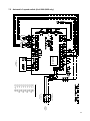
Manual 2-speed switch (Xcell 200 QV only) .......................................................................................... 12
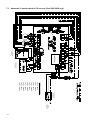
Automatic 3-speed switch (Xcell 200 QVW only) ................................................................................... 13
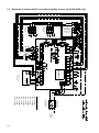
Automatic 3-speed switch & CO2 sensor (Xcell 200 QVW only) ............................................................ 14
Automatic 3-speed switch, CO2 sensor & up to three humidity sensors (Xcell 200 QVW only) ............ 15
Automatic 3-speed switch & up to four humidity sensors (Xcell 200 QVW only) ................................... 16
Manual 2-speed switch (Xcell 200 QV model only) ............................................................................... 17
Automatic 3-speed switch (Xcell 200 QVW model only) ........................................................................ 17
CO2 sensor (Xcell 200 QVW model only) .............................................................................................. 18
Humidity sensor (Xcell 200 QVW model only) ....................................................................................... 18
Automatic defrost protection (Xcell 200 QVW model only) .................................................................... 18
Fan fault monitoring (Xcell 200 QVW model only) ................................................................................. 19
Defrost heater unit .................................................................................................................................. 19
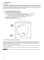
Maintenance .............................................................................................................................. 20
9.1
Filters ...................................................................................................................................................... 20
9.1.1
Removing and re-fitting the filters ................................................................................................... 20
9.2
Air filter box (optional accessory) ........................................................................................................... 20
9.3
Cleaning the heat exchanger ................................................................................................................. 21
10 Malfunctions .............................................................................................................................. 21
10.1
10.2
Fault locating table ................................................................................................................................. 21
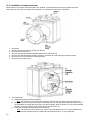
Installation of replacement fans ............................................................................................................. 22
11 Customer Notes (to record details of filter / recuperator cleaning etc.) ................................ 24
Maintenance Log ............................................................................................................................. 26
GUARANTEE.................................................................................................................................... 28
2