1
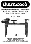
8” x 5” PLANER THICKNESSER
OPERATING INSTRUCTIONS
MODEL: W588
Charnwood, Cedar Court, Walker Road, Bardon, Leicestershire, LE67 1TU
Tel. 01530 516 926 Fax. 01530 516 929
Email; [email protected] website; www.charnwood.net
Introduction
To get the most out of your new planer thicknesser, please read through this manual and safety
instructions before use. Please also save the instructions in case you need to refer to them at a
later date.
Technical data
Voltage/frequency
Power rating
Planer:
Planing width
Planing depth
Work table
Working height
Fence
Angle range
Thicknesser:
Planing width
Capacity
Planing depth
Work table
Feed-in speed
No. of blades
Extractor outlet
230 V ~ 50 Hz
1500 W
200 mm
0-3 mm
740 x 210 mm
360 mm
530 x 100 mm
90-135°
200 mm
5-127 mm
0-2 mm
270 x 210 mm
8 m/min
2
100 mm dia.
Main components
1. Rear table
2. Guide fence
3. Blade guard arm
4. Blade guard
5. Width adjustment knob
6. Angle adjustment knob
7. Depth adjustment handle (thicknesser)
8. Front table
9. Plane depth adjustment knob (plane)
10. Blade housing
11. On/off switch
12. Stabilising holes
13. Thicknesser table
14. Plane depth indicator
15. Arm adjustment knob
16. Hole for depth adjustment (in back table)
An extractor nozzle, tools and blade adjustment gauge are also included (not llustrated here).
2
Special safety instructions
For planing wood only.
Never use the machine if the blade is not correctly locked in the blade housing.
When not in use, cover the blade housing.
Use a piece of scrap wood as a pusher when planing small items.
Never allow fingers or tools to get near the blade when machine is in use.
Never try to plane across the grain.
Test on/off switch regularly.
3
Mounting
Place on a level, stable surface.
Fit the side guide (2) using the two screws supplied.
Fit blade guard arm (3) to rear table (1) opposite side guide.
Stabilise machine if required by passing a piece of wood through stabilising holes (12) on base.
This is advisable if large items are to be planed.
Attaching extractor hose
Planing
Turn depth adjustment handle (7) anti-clockwise to fully lower thicknesser table (13).
4
Connect extractor hose to thicknesser table under the front table. The three studs in the extractor
nozzle slot into the corresponding holes on the table.
Raise thicknesser table again by turning handle clockwise, until nozzle fits tightly to underside of
table.
Fit adapter on nozzle and connect to extractor system.
Thicknessing
Slacken width adjustment knob (5) on blade guard (4), and push clear of blade housing (10).
Fit extractor to back table using handle (a).
Fit adapter on nozzle and connect to extractor system.
Setting guide fence
Set guide fence at desired angle (90-135°) using adjustment screw (b)
Insert plug in mains socket.
5
Use
Planing
IMPORTANT: The Dust Extaction Hood must be fitted underneath the cutterblock before
operating the machine.
Sensors will detect if the hood is not fitted correctly and disable the switch.
Turn adjustment knob (9) to lower front table to desired height. Planing depth can be seen
on indicator (c)
Place workpiece on front table and set blade guard to required height using arm adjustment knob
(15).
6
The workpiece should be able to pass unhindered under the guard.
Set guide fence angle, if planer is to be used for beveling.
Start machine at on/off switch (11).
Slide item slowly and steadily towards blade.
Thicknessing
IMPORTANT: The Dust Extaction Hood must be fitted over the cutterblock before operating
the machine. Sensors will detect if the hood is not fitted correctly and disable the switch.
Arrange blade guard over blade housing and secure in place.
Set thicknesser to desired depth using handle.
Planing depth can be seen on indicator (14).
Start machine.
Place workpiece on thicknesser table on side of machine with arrow, and slide slowly and
steadily forward with side to be planed facing upwards.
Wedge-shaped items must be planed thick end first.
7
General
Switch off machine after use and remove chips and dust from blades.
Cleaning and maintenance
Always disconnect machine from mains before performing maintenance!
Servicing and replacing blades
Remove side guide and blade guard. Slacken screws (d) with the screwdriver supplied.
Turn blade housing until holder (e) and blade (f) can be removed.
Clean mounting bearings, blade housing and blade with an oily cloth. Replace or sharpen blade if
blunted.
Fit blade and holder in blade housing.
Place blade adjustment gauge (g) on rear table and check blade height is even both ends.
Tighten screws with screwdriver.
Check blade can revolve freely.
Fit guide fence and cover blade housing with blade guard.
8
General cleaning
Remove dust and chips regularly from machine with a brush or compressed air. Check that motor
ventilation slots are not blocked.
Lubricate all bearings and moving parts regularly with oil. Avoid getting oil on drive belt.
Regularly remove sap and the like from the front and rear tables with household spirit or
petroleum.
Environmental information
Please dispose of packaging for the product in a responsible manner. It is suitable for recycling.
Help to protect the environment, take the packaging to the local amenity tip and place into the
appropriate recycling bin.
Only for EU countries
Do not dispose of electric tools together with household waste material!
In observance of European Directive 2002/96/EC on waste electrical and electronic equipment
(EEE) and its implementation in accordance with national law, electric tools that have
reached the end of their life must be collected separately and returned to an environmentally
compatible recycling facility.
Your local refuse amenity will have a separate collection area for EEE goods.
9
Charnwood W588 Parts List
Part No
Description
Part No
1 Chain tensioning rivet
2 Chain tensioner
3 Open Collar 6
4 Spring washer 5
5 Nut M5
6 Flat Washer 5
7 Adjustable Chain Wheel
8 Chain 2 (p=8)
9 Positioning table rivet
10 Press & shaving material sign
11 Hexagon bolt M5 x 12
12 Negative Leading screw
13 Active Leading screw
14 Hexagon Socket Stud Bolt M5x20
15 Open Pin 3x15
16 Sleeve
17 Racket
18 Workbench Weld Component
19 Crank Connect block
20 Guide Plate
21 Hexagon Bolt M8x20
22 Crank Stop
23 Crank Bolt
24 Crank Nip
25 Hexagon Bolt M8x20
26 Flat Washer 4
Cross Recessed Raised Pan Head Screws
27 M4x10
28 Spring Washer 4
29 Pressing And Shaving Feeding Pointer
30 Rubber Footing
31 Nut M4
32 Cable Clip
33 Cross Recessed Raised Pan Head Screws M4x16
34 Footing Cover Plate (B)
35 Auxiliary Station Plate Welding Component
36 Tapping Screw ST4.2x10
37 Rising/Lowering Scale Sign
38 Hexagon Bolt M5x8
39 Curve Preventing Sheath
40 Cover
41 Wires
42 Tapping Screw ST4.2x20
43 Power Supply Line (Plug)
44 Bolt
45 Lock Spring
10
Description
46 Lock Bolt Components
47 Cap Nut M5
48 Big Flat Washer 5
49 Coupling Stud
50 Locating Bush Fixed Workbench
51 Locating Bush Moving Workbench
52 Nail Bearing K10x13x13
53 Block Tension Spring(B)
54 Block
55 Block Tension Spring
56 Roller Component
57 Planer Blade
58 Planer Blade Spring
59 Spring Pin 3x8
60 Planer Blade Binder Plate
61 Binder Plate Bolt
62 Bearing
63 Nut M6
64 Fixed Workbench
65 Flat Washer 4
66 Hexagon Bolt M4x12
67 Goniometer (A)
68 Flat Washer 6
69 Spring Washer 6
70 Male Hexagon Bolt M6x12
71 Goniometer Mount
72 Hexagon Socket Locating Screw
73 Hexagon Bolt M6x25
74 Big Flat Washer 6
75 Lock Screw
76 Angle Pointer
77 Spring Pin 3x10
78 Locking Axis
79 Angle Iron
80 Male Hexagon Bolt M4x15
81 Goniometer (B)
82 Ruling Plate Welding Component
83 Dust Exhaust Hood
84 Open Collar 6
85 Dust Exhaust Hood
86 Open Collar 6
87 Planing Pointer
88 Planing Pointer Sign
Cross Recessed Raised Pan Head
89 M5x12
90 Knob
Part No
Description
Part No
91 Adjusting Bar
92 Lock Nut M8
93 Lever
94 Insert Block
95 Stopper
Description
136 Square Bush
137 Big Gear
138 Connection Plate Rivet
139 Connection Plate Tensioning Spring
140 Axis Collar (12)
Cross Recessed Raised Pan Head Screws
141 M5x12
142 Spring Washer 3
143 Flat Washer 3
144 Cable Clip
145 Micro-Switch Connecting
146 Driving Pulley
147 Ajar Block Screw
148 Micro-Switch Block
149 Eccentrc Axis Washer
150 Spring Washer 8
Hexagon Half Socket Button Head Screws
151 M8x15
152 Motor
153 Footing Cover (A)
154 Exterior Teeth Locking Gasket 4
155 M16 Fastener
156 Switch Box Mount
Cross Recessed Raised Pan Head Screws
157 M5x10
158 7A Overload Protector
159 Switch Box Cover
160 Tapping Screw T4.2x15
161 Thin Nut M12
162 KJD12-16 Main Switch
163 Eccentric Axis
164 Movable Workbench
165 Brush Housing Fixing Screw M4x12
166 Cable Clip (Motor)
167 Motor Shell
168 Brush Housing
169 Carbon Brush
170 Nut
171 Ball Bearing 6101
96 Tapping Screw ST4.2x6
97 Locking Bush
98 Cantilever Components
99 Bridge Supporting Welding Component
100 Locking Knob
101 Locking Knob
102 Shield Plate
103 Location Limit Screw
104 Locking Clamping Plate
105 Location Clamping Screw
106 Locating Screw
107 Catch
108 Hanging Rod
109 Gasket (brake)
110 Brake
111 Bearing Cover
112 Ball Bearing (6000-2Z)
113 Main Station Plate Welding Component
114 Feeding Scale Sign
115 Ajar Block Spring
116 Hexagon Bolt M5x10
117 Ajar Washer (B)
118 Macro Switch (Idler Wheel Style)
119 Arbor Belt Wheel
120 Multi-Wedge Belt (5PJ604)
121 Bush
122 Big Chain Wheel
123 Hexagon Socket Button Head Screws M6x15
124 Driving Chain (P=12.7)
125 Pinion
126 Multi-Wedge AL Belt Wheel
Cross Recessed Raised Pan Head Screws
127 M5x20
128 12 Axis Collar
129 Multi-Wedge Belt (3PJ604)
130 Coupling Stud
131 Housing
132 Main Sign
133 Axis Collar 9
134 Washer (Connection Plate)
135 Small Chain Wheel
172 Inductance
173 Stator-End Insulation
174 Armature
175 Stator-End Insulation
176 Stator Terminal Insulation
177 Tapping Screw ST5x56
178 Vane
179 Ball Bearing 80201
180 Motor Cover
11
Charnwood W588 Exploded View Diagram
12