1
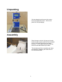
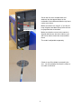
Machinery & Tooling at its best!
10” BANDSAW
OPERATING INSTRUCTIONS
MODEL: W715
Charnwood, Cedar Court, Walker Road, Bardon,
Leicestershire, LE67 1TU
Tel. 01530 516926 Fax. 01530 516929
email; [email protected] website; www.charnwood.net
GENERAL SAFETY RULES
WARNING: Do not attempt to operate the machine until you have thoroughly read and understood
completely all instructions, rules, etc. contained in this manual. Failure to comply may result in
accidents involving fire, electric shock, or serious personal injury. Keep this owner's manual and
review frequently for continuous safe operation.
1. Know your machine. For your own safety, read the owner's manual carefully. Learn its
application and limitations, as well as specific potential hazards pertinent to this machine.
2. Make sure all tools are properly earthed.
3. Keep guards in place and in working order. If a guard must be removed for maintenance or
cleaning, make sure it is properly replaced before using the machine again.
4. Remove adjusting keys and spanners. Form a habit of checking to see that the keys and
adjusting spanners are removed from the machine before switched it on.
5. Keep your work area clean. Cluttered areas and workbenches increase the chance of an
accident.'
6. Do not use in dangerous environments. Do not use power tools in damp or wet locations, or
expose them to rain. Keep work areas well illuminated.
7. Keep children away.
8. All visitors should be kept a safe distance from the work area.
9. Make workshop childproof. Use padlocks, master switches
and remove starter keys.
10. Do not force the machine. It will do the job better and be safer at the rate for which it is
designed.
11. Use the right tools. Do not force the machine or attachments to do a job for which they are
not designed. Contact the manufacturer or distributor if there is any question about the
machine's suitability for a particular task.
12. Wear proper apparel. Avoid loose clothing, gloves, ties, rings, bracelets, and jewellery which
could get caught in moving parts. Non-slip footwear is recommended. Wear protective hair
covering to contain long hair.
13. Always use safety glasses. Normal spectacles only have impact resistant lenses. They are not
safety glasses.
14. Do not over-reach. Keep proper footing and balance at all times.
15. Maintain the machine in good condition. Keep the machine clean for best and safest
performance. Follow instructions for lubrication and changing accessories.
16. Disconnect the machine from power source before servicing and when changing the blade.
2
17. Never leave the machine running unattended. Turn the power off. Do not leave the
machine until it comes to a complete stop.
18. Do not use any power tools while under the effects of drugs, alcohol or medication.
19. Always wear a face or dust mask if operation creates a lot of dust and/or chips. Always
operate the tool in a well ventilated area and provide for proper dust removal. Use a
suitable dust extractor.
ADDITIONAL RULES FOR BAND SAWS
1. Ensure that the saw table is clear of off-cuts, tools or anything else that might foul the workpiece.
2. When cutting long boards use one or more roller stand(s) to support the work or have a
competent helper to support it as it feeds off the rear of the table.
3. Always make sure that the blade is tracked and tensioned correctly before starting to use
the saw.
4. Always use a brush to clear the table of dust or debris. NEVER use your hands, especially
when the machine is running.
5. Always ensure that the thrust bearings and guide blocks are correctly adjusted before using
the saw.
6. ALWAYS USE A PUSH STICK WHEN IT IS NECESSARY TO PUSH ANY PIECE OF MATERIAL OF
SUCH SIZE THAT IT WOULD BRING YOUR HANDS WITHIN 30 CM OF THE BLADE.
7. Do not cut material that is badly warped or which has screws or nails in it.
8. Be extra vigilant when cutting stock which has loose knots in it as these my fly out of the
saw.
9. NEVER tilt the table when the saw is running.
10. To avoid exposure to hazardous dust, do not use this saw without connecting it to a suitable
dust extractor.
11. Always work with a sharp saw blade and feed the work at a rate suited to the thickness and
hardness of the material.
Note: This band saw has been designed and built solely as a woodworking machine. Do not modify it
in any way or use it for anything other than its designated purpose. Neither the manufactures nor
the supplier are liable for any damage or injury caused by incorrect assembly, operation or electrical
connection of this machine.
3
Specification
Table size
340 x 335 mm
Motor
370W
Blade length
1712 mm
Blade speed (no load)
1400±10% m/min
Blade widths
6 to 12 mm
Maximum depth of cut at 90o
100mm
Maximum depth of stock at 45o
70mm
Throat capacity
250mm
Dust extractor hose connection
40mm
Weight
30kg net
Features
Precision ground, cast iron table with adjustable scale on rip fence carrier
0 to 45o table tilt
High Quality, British made blade
Easily portable machine
Quick release, positive lock rip fence
Cross cut/mitre fence with easily read scale
Tool free blade tracking and tensioning
4
Unpacking
Cut the strapping and remove the carton
from the polystyrene insert. Remove all
parts from the packaging
Assembly
Place the saw, so that it is lying on its back.
Hold the table in place with the four threaded
holes in line with the holes in the upper
trunnion. Fix it in place with two of the four
bolts and serrated washers provided
Tilt the table and fit the remaining two bolts
and washers, tightening the bolts after all
four have been fitted.
5
Screw the four hex, headed bolts and
washers into the tapped holes on the
underside of the table and slide the rip fence
carrier on to them.
Make sure that it is a snug fit. If you do not
keep it tight to the table the rip fence will not
be perpendicular to the table.
Make sure that the cut out in the carrier is
aligned with the tee slot in the table or you
will not be able to insert the crosscut/mitre
fence.
The scale is adjustable separately
Check to see if the blade is centred in the
slot. You will probably find that it is offset to
one side or the other.
6
The lower trunnion is attached to the body of
the saw by four hex headed bolts.
These may be slackened and the trunnion
slid in either direction until the blade is
centred.
After adjustment, tighten them securely.
Adjustable pointer.
This lever locks and unlocks the trunnion so
that the table may be tilted.
Having set the table so that the blade is
centred, apply a little tension to the blade
and use a set square to position the table at
right angles to it.
Lock it in position and if necessary, adjust
the pointer so that it aligns with the zero as
shown above
7
Screw in and lock the push stick hanger on
the back of the frame.
This completes the assembly of your saw.
Setting up your saw
Blade tensioner
Blade guard positioner and lock
Tracking control and lock
Adjust the blade tension by hand wheel on
top of the upper housing.
‘Pluck’ the back of the blade, as you would
the string of a double bass, at this
point. As the blade tension is increased, the
pitch of the sound will rise. Stop increasing
the tension as soon as the sound starts to
become dull. Alternatively, raise the blade
guard to its highest position and adjust
tension until the blade, at the midpoint
between table and guard can be deflected
only 3 to 5 mm with finger pressure.
Turn the upper wheel clockwise, by hand
and adjust the tracking control until the blade
is centred on the wheel, as shown in the
inset illustration. Lock the adjuster in this
position.
8
The upper and lower thrust bearings and
guide pins should be set up next.
Thrust bearing
Guide pin
Guide pin locking screw
Thrust bearing locking screw
The thrust bearing should be about 0.5 mm
behind the back of the blade. Adjust it and
lock it place.
Slacken the guide pin locking screws, push
the pins in until they touch the blade. Rotate
the top wheel by hand a few turns and lock
the pins in the position they have assumed.
The lower thrust bearing and guide pins are
adjusted similarly.
Guide pin locking screw
Guide pin
Lower thrust bearing
Blade guard
The scale is adjustable and can be slid
within its housing by slackening this
screw.
9
This bandsaw is equipped with a rip fence
and a cross cut/mitre fence which can be
fitted as shown.
The rip fence may be used on either side of
the blade and may also serve as a length
stop for repetitive cross or mitre cuts.
Your bandsaw is now ready for use but it is recommended that it be bolted to a bench and
that a suitable dust extractor is connected.
Changing the Blade
Bandsaw blades are sharp enough to cause injury even when too blunt to cut wood! It is
recommended that protective gloves be worn when handling blades.
Unplug the bandsaw from the mains socket, slacken off the blade tension and open the
upper and lower housing doors with the aid of a suitable screwdriver.
Remove the rip fence carrier.
Loosen the bolt and swing the
lower blade guard out of the
way.
10
Lower the upper blade guide
Remove the rip fence carrier
(shown here still in place)
Slide blade off upper and lower
wheels, bringing it out of the
machine via the slots in the rear
frame and the blade guard.
Reverse these steps to fit the new blade. Ensure that the teeth are at the front and pointing
down.
Position the blade between the guide pins. Tension and adjust the tracking as done during
the initial set up. Check and adjust, if necessary, the position of the two thrust bearings and
the guide pins.
11
Parts List
Item
Description
Quantity
1
2
3
4
5
6
7
8
9
10
11
12
13
14
15
16
17
18
19
20
21
22
23
24
25
26
27
28
29
30
31
32
33
34
35
36
37
38
39
40
41
42
43
44
45
46
47
48
Slotted Insert
Washer
Housing
Washer
Lower Door
Housing, with nut
Tongue
Ext. lock washer 6mm
Hex. head bolt M6x10
Upper door
Saw blade
Retaining ring
Ball bearing
Upper wheel
Balance collar
Tyre
Upper bearing bolt
‘E’ rings
Pin guide
Upper seat bearing bolt
Hex head flange nut
Guide plate assembly
Countersunk set screw
NVR switch
Switch plate
Ext. lock washer
Pan head set screw
Blade tensioner
Frame
Back plastic plug
Blade tensioner tracking knob
Nut
Threaded rod
Washer
Hex head bolt
Hex head bolt
Wing nut
Washer
Washer
Nut
Shaft
Spring
Hex head flange nut
Spacer
Brush
Square head bolt
Hex head lock nut
Lower blade guard
3
3
3
3
1
3
3
3
5
1
1
2
4
1
1
2
1
2
1
1
8
1
2
1
1
2
2
1
1
1
21
1
1
8
9
1
1
10
1
1
1
18
1
1
1
1
2
1
12
49
50
51
52
53
54
55
56
57
58
59
60
61
62
63
64
65
66
67
68
69
70
71
72
73
74
75
76
77
78
79
80
81
82
83
84
85
86
87
88
89
90
91
92
93
94
95
96
97
98
99
100
101
Lower trunnion
Washer
Cap head screw
Thrust bearing retaining block
Guide pin
Thrust bearing shaft
Thrust bearing
Setting screw
Hex. head bolt
Table insert
Table
Coach bolt
Guide piece
Upper trunnion
Indicator
Tilt locking lever
Hex. head bolt
Nut
Hex. head bolt
Rip fence carrier
Roll pin
Rip fence locking lever
Spindle
Rip fence slide
End cap
Fence
Spring
Clamp
Threaded rod
Shaft
Upper blade guide bracket
Self tapping screw
Upper blade guide housing
Cap head screw
Cap head screw
Upper blade guide - fixed piece
Upper blade guide - movable piece
End cap
Screw
Rack
Guide
Upper blade guard adjustment knob
Lock nut
Screw
Lower wheel
Driven pulley
Drive belt
Key
Motor pulley
Coach bolt
Nut
Spring washer
Upper bearing bolt
1
1
3
1
2
4
4
1
8
1
1
1
1
1
1
1
1
5
4
1
1
1
1
1
2
1
1
1
1
1
1
2
1
3
2
1
1
1
4
1
2
1
1
3
1
1
1
1
1
4
1
1
1
13
102
103
104
105
106
107
108
109
110
Spring washer
Motor mounting plate
Motor
Motor cable
Mains cable
Nut
Hex head bolt
Strain relief
Shaft
4
1
1
1
1
2
4
2
1
14
15
Machinery & Tooling at its best!
Charnwood, Cedar Court, Walker Road, Bardon,
Leicestershire, LE67 1TU
Tel. 01530 516926 Fax. 01530 516929
email; [email protected] website; www.charnwood.net