1
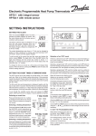
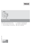
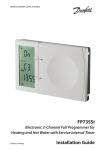
FH-RT Wireless Room Thermostat
FH-BU Wireless Base Unit
Installation & Operating Instructions
Specification
Power
Base unit (230 V)
Order Code:
Primary voltage:
Secondary voltage:
Outputs 1-6:
088H012000
230 V a.c.
230 V a.c.
230 V a.c., 1 A max., relay
controlled
8 A, 230 V a.c./50 Hz, relay
controlled, convertible to
volt-free outputs
Outputs 7-8:
Max. no. of thermostats:
Max. no. of thermal actuators:
Max. no. of thermal actuators
per output:
8 (wireless)
20
Output 8 run-on time:
Thermal actuator & pump exercise
10 min
Once daily (approx. every 24
hours after connecting the
power supply for the first
time)
Settings after power failure:
Enclosure:
Dimensions [mm]
Ambient temperature:
Humidity:
User settings are retained
IP20
310 x 110 x 55
0-50°C
Less than 85%
1
Mode
2
3
4
5
6
7
8
OK
4
20
10
Thermostat
Order Code:
Temperature scale:
Hysteresis:
Scale accuracy:
Night set-back:
Frequency:
Battery life:
Battery type:
Transmission range:
Transmission interval:
Ambient temperature:
Humidity:
30
❄
088H012100
6-30°C +/- 2K
+/- 0.5°C
2K around set point
4K at 20°C
433.70 MHz
Min. 5 years
3.6 V lithium battery, 2100
mAh, size AA
Up to 30 m (radius)
2-30 min
0-50°C
Less than 90%
System Schematic
FH-RT ROOM THERMOSTATS
OPTIONAL
EXTERNAL
ANTENNA
FH-BU WIRING BOX
Mains in
THERMAL
ACTUATORS
MANIFOLD
FLOOR
LOOPS
Zone1
Zone2
Zone3
Pump Interlock
Boiler Interlock
1
These installation and operating instructions describe system function and technical data.
The system is a complete floor heating control system for individual rooms in dwellings, offices, institutions, business
premises, etc.
The system is based on data transfer via radio, and is therefore quick and easy to install.
The system was developed to meet requirements for comfort, heat economy, flexibility and user-friendly operation.
Power
1
Mode
2
3
4
5
6
7
8
OK
20
10
30
❄
Fig. 1. The system consists of a base unit, thermostat and, if necessary, an external aerial.
2.0 Operating principle
The system consists of two unit types: base unit and thermostat.
The base unit is connected to a 230 V supply and through eight
outputs controls the thermal actuators that regulate the flow of hot
water to the individual rooms. The system can also control
circulation pump and boiler. The base unit is centrally located in the
dwelling adjacent to the distribution manifold.
2.1 Base unit
The base unit is the system interface. It consists of a control panel,
radio receiver and alarm.
If faults occur in the wireless data transfer, the base unit raises an
alarm in order to make users aware of the fault. The alarm also
informs the user when a thermostat requires a new battery. The
receiver in the base unit continuously scans the radio signals it
receives from installed thermostats.
The base unit is usually installed about 1.5 metres above the floor in
order to make the control panel easily accessible. Installation at this
height also enhances the radio signal range of the system.
2.2 Thermostat
Up to eight thermostats can be connected to the system. One
thermostat can be used to control several thermal actuators.
Thermostats are positioned at suitable locations in rooms where
temperature control is required. Thermostats have a knob for setting
the desired temperature and a switch for selecting one of three
programs (day, timer control and night).
Each thermostat contains a small battery that supplies current to an
electronic temperature measuring circuit with associated radio
transmitter. At suitable intervals the measured temperature is sent as
a radio signal to the radio receiver in the base unit. If the
temperature is changed the thermostat will transmit the new
temperature after the suitable interval. For transmission test please
see section on Transmission Testing, or Thermostat Test Mode.
Thermostats have no external cable connections.
Each thermostat has a unique identification (ID) number that is sent
with every transmission. The base unit uses these ID numbers to
distinguish the various thermostats. Thermostats must therefore be
registered in the base unit before the unit is able to receive data
from the thermostats.
2
During registration, thermostats transfer their ID numbers to the
base unit. The use of ID numbers also prevents the base unit from
reacting to signals received from neighbouring systems or other
systems based on radio technology.
Thermostats are battery powered and thus fully mobile, making it
easy to re-configure the system if required.
The system is CE marked and approved for use in all EU and former
EFTA countries.
The actual temperature is measured by the thermostat. When the
actual temperature is lower than the set temperature, a command
for heat is sent to the base unit.
Temperature can be set between 6°C and 30°C. A function switch
on the thermostat allows day, timer control or night to be selected.
The day setting allows normal operation, the timer setting allows
time-controlled night set-back to be used, and the night setting
permanently lowers the temperature setting by 4°C.
Thermostats are supplied with pre-installed batteries. Before being
taken into use, thermostats are “dormant” and only begin measuring
temperature and transmitting data on being registered in the base
unit for the first time. The purpose of this dormant state is to
minimise energy use during storage and to avoid unnecessary radio
transmission.
On being installed for the first time, thermostats automatically enter
test mode so that transmission can be tested immediately.
Battery life is guaranteed by the manufacturer to be at least 5 years.
A complete system is illustrated above in Fig. 1.
2.3 Aerial
Normally, the base unit uses a built-in aerial.
The location of the base unit is therefore important for the range,
which can be increased by equipping the base unit with an external
aerial.
An external aerial must be used if the base unit is located in a metal
cabinet.
3.0 Installation instructions
4.0 Operating instructions
The system should be installed by a competent person in the
following sequence.
4.1 Thermal actuator installation
1.
3.1 Base unit
Install the base unit first. Mount the base unit above the distribution
manifold either direct on the wall or inside a wooden or metal
distribution cabinet. Ensure that the base unit is mounted
horizontally, that there is easy access to the control panel and
thermal actuator connections, and that the base unit cover can be
easily removed. Fix the base unit to the wall using two screws.
The base unit must be connected to a 230 volt supply via a double
pole switch socket outlet. If it is installed in a metal distribution
cabinet, an aerial should be installed outside the cabinet in order to
improve radio communication.
2.
3.
4.
5.
6.
7.
8.
9.
Ensure that the power supply to the base unit is
disconnected.
Lift base unit cover after loosening front screws.
Remove internal aerial.
Remove blue thermal actuator terminals from printed circuit
board.
Connect thermal actuator cables.
Reattach thermal actuator terminals in assigned order to
printed circuit board.
Position cables in strain-relief cable glands (see Fig 3).
Replace internal aerial.
Close base unit and tighten front screws
3.2 Thermostat installation
Thermostats should be mounted on an internal wall at a height of
1.2-1.5 metres above the floor, using screws and fixings.
Thermostats must not be placed on an external wall or near heat
sources such as television and stereo sets, ovens or similar.
Thermostats should not normally be placed where they can be
affected by direct sunshine. In rooms that are very humid or damp,
e.g. bathrooms, thermostats must be placed as far from moisture
sources as possible.
3.3 Pre-installation
Thermostats must be registered in the base unit before being placed
in individual rooms.
When registering thermostats, it is important that the room in which
they are to be placed is written or marked on the rear of the
thermostat. Thermostats can then be registered in turn.
The channels to be used for individual rooms must therefore be
decided in advance.
Note: refer to section 4.3 for registration instructions
Fig. 3. Push cable through cable gland.
4.2 Base unit installation
Once the base unit has been mounted on the wall, all thermal
actuators have been connected and any connections for pump and
boiler control have been made, the thermostats can be registered.
First, power up the base unit. The green ‘Power’ LED lights up.
Ca. 1,5m
Fig. 2a. Thermostat location
Power
1
Mode
2
3
4
5
6
7
8
OK
Fig. 4. Control panel. LED indicators 1-8 and ‘Power’ LED.
Fig. 2b. Thermostat installation
3
4.3 Thermostat registration
To get the FH-BU base into registration mode
Press and hold “MODE” and “OK” buttons on base unit for 3
seconds, (all LED’s will flash) then release “MODE” and finally
release “OK”. The system is now in registration mode. Only the
“POWER” LED should be on (unless thermostats already have been
assigned earlier- then the LED for these will be on)
Fig. 6. De-registering thermostats
Note: The system returns automatically to normal mode if no buttons
are pressed during a 5-minute period.
4.5 Setting room temperature
The temperature is set by turning the thermostat setting knob to the
desired temperature.
Fig. 5. Registration mode
Thermostat registration process
Using the point of a pencil press the thermostat transmission button.
The LED for the first available channel (1-8) will start to flash. Select
the channel to be assigned to the thermostat by pressing the “MODE”
button numerous times until the LED for the desired channel flashes.
Then press and hold “OK” for 3 seconds (the LED will flash and
finally be on). The thermostat is now registered. Repeat the
thermostat registration process for each thermostat. (Also if one
thermostat should be assigned to several channels).
After registering all thermostats, press and hold “MODE” for 3
seconds (all LED’s will flash), to return the system to normal mode.
Note: The system returns automatically to normal mode if no buttons
are pressed during a 5-minute period.
4.4 De-registering thermostats
To get the FH-BU base unit into de-registration mode
Press and hold “MODE” and “OK” buttons for 3 seconds, (all LED’s
will flash) then release “OK”, and finally release “MODE”. The
system is now in de-registration mode. (If only one thermostat is
assigned the first assigned LED will start to flash).
Press the thermostat transmission button. The LED for the first
assigned channel will start to flash, (the rest will be on). Select the
channel to be de-registered by pressing the “MODE” button
numerous times until the LED for the desired channel flashes. Then
press and hold “OK” for 3 seconds, (the LED will flash and finally go
out). The channel is now de-registered. Repeat the thermostat deregistration process for each channel to be de-registered.
After de-registering thermostats, press and hold the “MODE” button
for 3 seconds (all LED’s flash) to return the system to normal mode.
4
4.6 Setting min./max. temperature
Lift thermostat cover.
Set min./max. temperatures using the red and blue limiters
respectively.
4.7 Setting thermostat operating mode
Switch position “sun” => normal => no night set-back.
Switch position “moon” => night set-back => 4°C at 20°C.
Switch position “clock” => timer-controlled set-back.
If timer-controlled set-back is required, it must be programmed via
the time clock/timer module (optional) fitted to the base unit.
5.0 Special functions
5.1 Master reset
This function deletes all registered data and reinstalls factory
settings.
Switch off the power supply, press and hold “OK” and “MODE”
simultaneously and keep pressing them while switching the power
back on.
LED indicators 1-8 then light up consecutively, and finally all eight
indicators flash. Release “OK” and “MODE”.
The system has now been reset to initial factory settings.
5.2 Transmission testing
Transmission testing is used to test and identify all registered
thermostats.
Press and hold “OK” for 3 seconds (all LED indicators flash).
All channels with assigned thermostats light up on the indicator
panel. When a channel receives a signal from a thermostat, the
corresponding indicator flashes twice and the indicators go off. If a
signal is subsequently received from the same thermostat, the
indicator for the corresponding channel flashes twice.
The test is automatically terminated once all channels have received
a signal from their assigned thermostat.
If no signal is received from one or more thermostats, the
corresponding LEDs on the indicator panel remain lit.
When the required number of thermostats have been checked,
press and hold “MODE” for 3 seconds to return the system to normal
mode.
Note: The system returns automatically to normal mode if no buttons
are pressed during a 15-minute period.
5.3 Thermostat test mode
This mode is used to test thermostat transmission.
Using the point of a pencil or similar, press and hold the transmission
button on the front of the thermostat for 3 seconds.
This forces the thermostat to transmit a signal every 7 seconds for
5-6 minutes.
can be de-activated by selecting the alarm “OFF” setting on the base
unit (see Fig. 9). The alarm is reset when a button on the control
panel is pressed or when the base unit receives a signal from the
thermostat.
5.6 Thermal actuator & pump exercise
This function prevents the manifold valve and circulating pump from
sticking.
It is activated once yearly. First, all assigned outputs are activated
for 5 minutes, and the pump output is then activated for 5 minutes
(only if pump output is installed).
The function can be turned off by switching the EXERCISE switch to
the OFF position. (See Fig. 10).
5.7 NO/NC thermal actuator settings
Then check whether a signal from the thermostat is received by the
base unit at 7 second intervals (the LED indicator for the assigned
channel flashes on receiving a signal).
The test can be terminated by again pressing the thermostat
transmission button.
Note: The system returns automatically to normal mode if no buttons
are pressed during a 5-minute period.
5.4 Thermal actuator output testing
Thermal actuator output testing is used to check the functioning of
the base unit output relays.
Press and hold the “MODE” button for 3 seconds (all LED indicators
flash).
The first indicator then begins flashing.
Press “OK” to test the first channel. The LED indicator now flashes
rapidly (on/off at half-second intervals) and a small click can be
heard after about 5 seconds indicating that the output has been
activated. Press “OK” again to de-activate the output.
Press “MODE” to select the next output to be tested, and repeat the
process described above.
The test can be terminated by pressing and holding the “MODE”
button for 3 seconds.
Note: The system returns automatically to normal mode if no buttons
are pressed during a 10-minute period.
This function allows “Normally Closed’ (N/C) or “Normally Open” (N/
O) thermal actuators to be used.
Type is selected on the ACTUATOR switch (see Fig. 10).
5.8 “Cooling” mode
This mode allows thermostat signals to be inverted so that outputs
are opened when the temperature is above the desired temperature
and closed when below and is intended for use in cooling systems.
6.0 Boiler and pump interlock setting
As standard, outputs 7 and 8 are set to control thermal actuators.
However, output 7 can also be used to control a boiler via an ON/
OFF signal, and output 8 can be used to control a pump.
To enable a boiler or pump to be controlled, the system must be
configured as shown in Figs 8 and 9 respectively.
Note: If outputs 7 and 8 are not used for thermal actuators, the
following applies:
LED indicators 7 and 8 light up when any other channel
requires heat
5.5 Alarm function
This function is initiated automatically in case of communication
failure.
If the base unit does not receive a signal from a registered
thermostat for 2 hours, the corresponding LED indicator starts
flashing. Simultaneously, the thermal actuator output begins a
continuous cycle of 7 minutes’ activation and 14 minutes’ deactivation.
If after a further 8 hours the base unit has still not received a signal
from the thermostat, an acoustic alarm begins buzzing. The buzzer
Fig. 8. Step 1. Remove right-hand jumper.
Fig. 7. Switches
Fig. 9. Step 2. Bend left-hand jumper as illustrated.
5
8.0 Drawing of Base Unit & Thermostat
Connector for LEDs and buttons on lid
Connector for timer module
Special functions
Fuse holders
Aerial socket
MMI
MODULE
ACTUATOR
NC -> NO
EXERCISE
OFF -> ON
BUZZER
OFF -> ON
TIMER
COOL
HEAT
OUTPUT 7
MODE
SELECTION
Thermal
actuator
output 7 alternatively:
boiler control
output
Thermal actuators outputs 1-6
Fig. 10. Base Unit
OUTPUT 8
MODE
SELECTION
Power supply
connectors
Thermal
actuator
output 8 alternatively:
pump control
output
DANSK VVS IMPORT
LED
indikator
LED
indicator
Transmission button
Transmissionsknap
Min/ Max
Min/max setting
indstilling
Indstilling af
Thermostat
natsænkning
mode switch
Fig. 11. Thermostat
9.0 Registration Record
Output
Channel
1
1
2
2
3
1
4
2
5
1
6
2
7/boiler (optional)
1
8/pump (optional)
2
Room
Circuit
Danfoss Randall can accept no responsibilty for possible errors in catalogues, brochures and other printed material. Danfoss Randall reserves the right to alter its products
without notice. This also applies to products already on order provided that such alterations can be made without subsequent changes being necessary in specifications
already agreed.
Danfoss Randall Limited,
Ampthill Road,
Bedford, MK42 9ER
Telephone: (01234) 364621
Fax: (01234) 219705
Email: [email protected]
Website: www.danfoss-randall.co.uk
6
Part No: 90092 Iss: 04 05/05