1
OPERATING INSTRUCTIONS FOR
AL-KO SECURITY DEVICE FOR AKS 1300 STABILISERS
ASSEMBLY INSTRUCTIONS
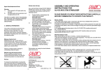
FITTING OF AL-KO SECURITY DEVICE
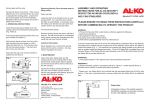
REMOVAL OF EXISTING FIXING BOLTS
Before you start to remove the existing fixing bolts, please note
the following: On most overrun assemblies, the shock absorber
is secured by the fixing bolt (Fig 4/Item 2).
Horizontal Bolt Fitting: (for AL-KO Overruns), Fig 6.
1 Locking plates left/right
2 Inner Hex. Bolt M12 8.8 with flat head to DIN 7984
3 Self locking nut M12
WARNING
The shock absorber (damper) extends independently. Enclosed
with this box is a retaining pin (Fig 5/Item 1) to aid assembly.
Cross-type Bolt Fitting: (for other overruns), Fig 7.
1 Locking plates left/right
2 Inner Hex. Bolt M12 8.8 with flat head to DIN 7984
3 Dome Head Bolt M12 8.8
4 Half moon shaped fixing lugs
5 Section washer (not included in this kit) - please use original
washer from coupling head you are removing
6 Self locking nut M12
a Remove gaiter and loosen self-locking nut from hexagon cap
bolt (Fig 4/Item 1 and Fig 5/Item 2)
c Push or knock out hex. cap bolt (Fig 4/Item 1)
d Knock through retaining pin (Fig 5/2) with (Fig 5/1). Leave the
pin in the shaft for centring the shock absorber (damper).
e Any spacers originally fitted must be re-used.
Illustrations show AK 160/300 couplings but assembly procedure for AKS 1300 is identical.
3
6
1
1
3
1
2
1
Fig 4
2
4
2
2
Fig 5
Fig 6
6
5
Fig 7
3