1
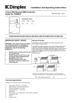
Installation and Operating Instructions
4 Zone Wall Mounted Pilot Wire Controller
Model No. RXPW4
November 2005—Issue 1
Dimensions (mm)
Height
Width
Depth
120
85
31
THESE INSTRUCTIONS SHOULD BE READ AND RETAINED FOR FUTURE USE
IMPORTANT SAFETY ADVICE
WARNING—This product must be installed
by a competent person or electrician in
conjunction with the current IEE Wiring
Regulations and relevant Building
Regulations
•
•
•
DO NOT cover or obstruct the air inlet
or air outlet vents
DO NOT recess the unit in to a wall,
as this will cause overheating and
potentially be a fire risk
DO NOT install the unit in the
immediate vicinity of a bathroom or
swimming pool
General Principle
The RXPW4 controller is compatible with Dimplex DuoHeat, EPX, EVS, RPXN,
Calidou and Apollo heaters.
The RXPW4 controller is designed to allow control of multiple Dimplex heaters
from a single point.
Each heater contains a mains cable with a fourth black pilot wire which can be
connected to heaters in a system in series.
The controller uses the pilot wire to conduct a 240V, low current signal to each
heater to change the heater mode (e.g. comfort, background or on, off)
Only one programmer is required for up to 20 heaters on the same zone. (See
Fig.1 below)
Pilot Wire Connection
IMPORTANT
Do NOT connect the pilot wire to earth
Care should be taken with the installation of the pilot wire(s)
as when switching to background (setback) they become
energised at 240V although only at a current of 1mA.
In every case a suitable means of isolation must be
provided for the pilot wire and marked to indicate that two
sources of supply may be present at the heater.
Where pilot wires are installed separately from the heater
final sub-circuit they should be protected, double insulated
and carry their own integral earth continuity conductor.
Note: Pilot wire installations are appropriate for single
phase connection only
= 240V domestic supply circuit
Technical Specification
Installation in an environment with normal pollution levels
•
•
•
•
•
•
•
•
Power supply—230V~AC, +/- 10%, 50Hz
Functioning temperature—0 to +40ºC
Storage temperature— -10ºC to 70ºC
Type of disconnection: micro-switching / 1.C type according to EN 60730-1
Clock back up in case of power failure—4 hours (approx.) Capacitor
Consumption—2VA
Class—II
Protection—IP30
Fig.1
Installation and Electrical Connection
WARNING—This product must be installed by a competent person or electrician in
The RXPW4 must be wall mounted as follows:
•
•
•
•
•
•
Remove single screw from underneath unit Fig.2 (1)
Separate base, remove bottom centre screw from base and remove cover to expose electrical connections Fig.3 (1) and Fig.4
Install the base with the appropriate screws and fixings for the wall type (not supplied) Fig.2 (2)
Connect the two supply wires to the corresponding Neutral (6) and Live (8) terminals in the base and connect pilot wire(s) (1-4) Fig.4
Position the unit on the base, first hooking the two recesses in the inside top over the hooks on the base then gently swing the unit
down so that the pins engage in the connector Fig.2 (3)
Finally, secure with single fixing screw underneath Fig.2 (1).
Fig.2
Fig.3
Fig.4
Controls
1 - Time (24hr)
2 - Day of the week
3 - Current mode: *
on or off
comfort or background
comfort or frost protection
4 - Mode display for each zone
5 - Modification / override buttons
6 - Validation button
7 - Timed absence mode (e.g.holidays)
8 - Selector switch index mark
9 - Mode selector switch (see Fig.6 and Table 2 below)
Table 1
Symbol
*Dependant on configuration (see ‘Programming—Heater Modes’ overleaf)
Function
Fig.5
Continuous comfort (all zones)
AUTO
Auto mode (heating runs to the preset program for each zone)
Continuous set back (all zones)
Continuous frost protection (all zones)
Set the time
PROG
Set the daily programs
Off (no heat output)
Fig.6
Configures heater modes
Table 2
Programming
Setting the time and day
1.
Turn the mode selector switch to the
2.
3.
4.
Press the ’+’ and ’-’ buttons to set the day
Press and hold the ‘+’ or ‘-’ button to cycle through the time faster.
Cycle through the time until the correct number corresponds with the present day (see Table 3)
(i.e. If the present day is Tuesday, cycle through the time until the number 3 starts to flash at the
top of the screen)
Once the present day is found set the time using the ‘+’ and ‘-’ buttons
5.
position. (see Fig.7)
Number
Day
1
Sunday
2
Monday
3
Tuesday
4
Wednesday
5
Thursday
6
Friday
7
Saturday
Fig.7
Table 3
Setting the daily program
1.
2.
3.
4.
5.
6.
7.
9.
10.
11.
Turn the mode selector switch to the ‘PROG’ position.
‘P=1’ will be displayed. for zone 1 to be programmed.
(To program another zone, press the ’+’ button and ’P=2’ will be displayed for zone 2)
Press ‘OK’ and ‘P=‘ will be displayed with the number ‘1’ at the top of the screen to signify the first day.
Press the ’+’ button for one hour of ’comfort’ or ’on’ and press the ’-’ button for one hour of ’background’, ’off’ or
’frost protection’ (depending on the configuration chosen).
If you wish to repeat a program for the following day, hold down the ‘OK’ button for 5 seconds and the
controller will automatically copy the current program over to the next day
Press ‘OK’ to confirm
‘2’ will now appear at the top of the screen to signify the second day. Repeat steps 4 and 5 until all seven days are programmed
After programming zone 1, ‘P=1’ will be displayed again. Now press the ‘+’ button to programme zone 2, ‘P=2’ will be displayed.
Press ‘OK’ and repeat steps 2-4
To run the program, set the mode selector switch to the ‘AUTO’ position
Fig.8
Fig.8
Configuration– Heater Modes
The controller can be configured to operate various heater modes, dependant
on the heating requirement. (As shown in Table 4)
1.
2.
3.
4.
5.
To change the configuration, turn the dial to the
position (see
Table 4 and Fig.9)
The display will change to ‘PARA’
Press and hold down the ‘+’ and ‘-’ buttons and C1=1 will be displayed
To change the setting to ‘C1=2’ or ‘C1=3’, press the ‘+’ or ‘-’ buttons
and press ‘OK’ to confirm (display returns to ‘PARA’)
If you wish to change these settings in the future turn the mode selector
switch to the
position and repeat steps 2-4.
Fig.9
Display
Mode
C1=1
Comfort and background
C1=2
On and Off
C1=3
Comfort and frost protection
Table 4
Operation
Running the daily program
Once the daily programmes have been set for each zone (see programming—setting the daily program) turn the dial to the Auto position.
The heaters in each zone will function as per the programme
Overriding the daily program
When the programmer is in Auto mode, the setting of each zone can be temporarily overridden.
With the dial in the Auto position:
1.
2.
3.
4.
5.
6.
Press the ‘OK’ button, the bar(s) above zone 1 will flash.
Change the status of zone 1 by pressing the ‘+’ and ‘-’ buttons. Zone 1 will change between 1 and 4 bars (see Fig.10 and Table 5)
Press ‘OK’ to confirm, the bar(s) for zone 2 will flash.
Repeat the above steps for zone 3 and 4.
If you do not wish to change the status of a particular zone, simply press ‘OK’ to move to the next zone
Pressing the ‘OK’ button for zone 4 will return the screen to the normal ‘AUTO’ display.
If no button is pressed in the override mode for 30 seconds the screen will automatically return to the ‘AUTO’ display.
NB—The override function for each zone will end at the beginning of the next program
To override all zones to the same mode, turn the mode selector switch to the relevant symbol.
See Fig.6 and Table 2 on page 2 for details.
Mode
No.of bars
Comfort / On
4
Setback / Off / Frost protection
1
Table 5
Fig.10
NB—The above table depends upon the configuration chosen (see page 3)
Absence mode (Holiday)
The RXPW4 incorporates a timed absence mode for when properties are vacant for a period of time
(e.g. holidays). All heaters in all zones will provide a frost protection temperature for a set period of time.
1.
2.
3.
4.
5.
Turn the mode selector switch to the ‘AUTO’ position.
Press and hold the ‘OK’ button for about 5 seconds.
‘Ab01’ will be displayed.
Press the ‘+’ and ‘-’ buttons for the amount of days you are away (up to 99 days).
At the end of the timed absence the controller will revert back to its original program.
Fig. 11
After Sales Service
Your product is guaranteed for two years from the date of purchase.
Within this period, we undertake to repair or exchange this product free of charge (subject to availability) provided it has been installed and
operated in accordance with these instructions. Your rights under this guarantee are additional to your statutory rights, which in turn are not
affected by this guarantee.
Should you require after sales service you should contact our customer services help desk on 0870 727 0101. It would assist us if you can
quote the model number, date of purchase, and nature of the fault at the time of your call. The customer services help desk will also be able
to advise you should you need to purchase any spares.
Please do not return a faulty product to us in the first instance as this may result in loss or damage and delay in providing you with a
satisfactory service.
Please retain your receipt as proof of purchase.
Glen Dimplex UK Ltd
Millbrook House
Grange Drive
Hedge End
Southampton
SO30 2DF
Customer Help Line
Tel: (0870) 727 0101 (8am-6pm Mon-Fri; 8:30am-1pm Sat.)
Fax: (0870) 727 0102
E-mail: [email protected]
Web-site: www.dimplex.com
Republic of Ireland Tel: 01 842 4833
[C] Glen Dimplex UK Limited
All rights reserved. Material contained in this publication may not be reproduced in whole or part, without prior permission in writing from Glen Dimplex UK Limited.