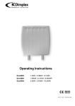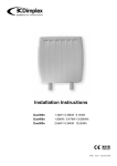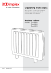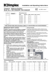
1
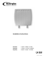
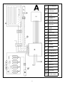
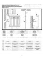
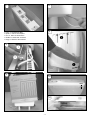
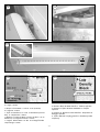
 Contact Details Please note that some of the contact details on this PDF document may not be current. Please use the following details if you need to contact us: Telephone: 0844 879 3588 Email: [email protected] The customer support section of our website also features a wide range of information which may be of use to you and is available 24 hours a day. It includes: • Operating and installation instructions • Easy ‘How to use’ guides for storage heaters • Service and repairs • Where to buy our products • Literature downloads • Heating requirement calculator Visit ‐ www.dimplex.co.uk/support A division of GDC Group Ltd
Millbrook House Grange Drive Hedge End Southampton SO30 2DF
www.dimplex.co.uk
Registered No: 1313016 England
VAT GB 287 1315 50004
EEE Producer Registration Number –
WEE/GE0057TS
Paper from sustainable sources
Installation Instructions
Duo300n
Duo400n
Duo500n
1.3kW / 0.38kW 9.1kWh
1.95kW / 0.47kW 13.65kWh
2.6kW / 0.54kW 18.2kWh
87452 : 4 : June 2009
-1-
A
A
Circuit Diagram
B
Charge Control
Thermostat
C
Over Temperature
Cut Out
D
StorageHeater
Elements
F
Room Sensing
Thermistor
G
Core Sensing
Thermistor
H
Charge Controller
Module
I
User Interface
Module
J
Peak Supply
K
Radiant Element
L
Live
N
Neutral
P
Pilot Wire
E
Manual Fit
Connector
L1
Live Storage In
L2
Live Storage Out
L3
Live Radiant In
L4
Live Radiant Out
S1
Signal In
S2
Signal Out
N1
Neutral In
N2
Neutral Out
M
-2-
Off Peak Supply
Dimensions (including clearances diagram) (millimetres)
Wymiary (w tym schemat minimalnych odległości)
(w milimetrach)
Dimensioni (incluso lo schema degli spazi
liberi) (millimetri)
Dimensions (y compris l’espace libre) (millimètres)
Dimensões (incluíndo diagrama de distâncias mínimas a
manter) (milimetros)
D
E
B
75mm
min.
G
250mm
min.
75mm
min.
C
150mm
min.
A
F
110mm
Height
Hauteur
Altura
Altezza
Wys.
Duo300n
Duo400n
712mm
712mm
600mm
830mm
130mm+10mm
130mm+10mm
Duo500n
712mm
1060mm
130mm+10mm
A
Width
Largeur
Comprimento
Larghezza
Szer.
Depth
Épaisseur
Espessura
Profondità
Gleb.
Model
Modèle
Modelo
Modello
Model
B
D
Curtains
E
Shelf or Overhang
F
Furniture or other
obstruction
Meubles ou autre
obstacle
Mobiliário ou outro
obstáculo
G
Wall
Mur
Parede
Rideaux
Cortinas
Tende
étagère ou consoles Prateleira ou objecto
Ripiano o sporgenza
murales
suspenso
-3-
C
Firanki
Półka lub część
wystająca
Mobile
o altro oggetto
Meble lub inne
elementy
Parete, tende o mobili
Ściany, firanki lub
meble
1
5
1
2
1
6
1. Feet 2. Accessories Bag
1. Pieds 2. Sac à accessoires
1. Pés 2. Saco de acessórios
1. Piedini 2. Sacchetto accessori
1. Nogo 2. Worek z akcesoriami
2
2
1
2
1
4
10A
10mm
10B
-4-
10F
10E
11A
30mm
1.
11c
11D
2.
6.
5.
7.
4.
3.
1. Brick 2. 8mm Drill 3. 3” No. 10 Screws (supplied)
4. Length +15mm
1. Brique 2. Foret 8mm 3. Vis N° 10 3” (fournies)
4. Longueur +15mm
1. Tijolo 2. 8mm Broca 3. 3” No. 10 Parafusos (fornecidos) 4. comprimento +15mm
1. Mattone 2. Punta da 8mm 3. Inserti in fibra n. 10 (in
dotazione) 4. Lunghezza inserto +15mm
1. Cegla 2. Wierto 8mm 3. 3” No. 10 4. Długość kołka
rozporowego +15mm
5. Plaster 6. Low density block 7. Special fixing
5. Enduit 6. Bloc de faible densité 7. Fixation spéciale
5. Estuque 6. Tijolo de baixa densidade 7. Fixação
especial
5. Intonaco 6. Blocchi a bassa densità 7. Dispositivo di
fissaggio speciale
5. Tynk 6. Material o mąłej gęstości 7. Plastikowy kołek
rozporowy.
-5-
12A
12B
12C
13
14
15A
16
15B
-6-
18
18A
18B
19A
19B
19C
19D
19E
19F
1
2
-7-
English
THESE INSTRUCTIONS SHOULD BE READ CAREFULLY AND RETAINED FOR FUTURE REFERENCE
NOTE ALSO THE INFORMATION GIVEN ON THE APPLIANCE
TO ENSURE THIS APPLIANCE IS OPERATING CORRECTLY, IT IS ESSENTIAL TO PERFORM THE CHECK PROCEDURE DETAILED
ON THE BACK PAGE OF THIS INSTRUCTION. THIS MUST BE COMPLETED BEFORE NORMAL OPERATION COMMENCES.
IMPORTANT SAFETY ADVICE
WARNING - This radiator is VERY HEAVY, it is essential that the radiator is FIXED SOUNDLY TO A WALL and mounted on
a FIRM, LEVEL SURFACE.
WARNING – Choose the appropriate fixings to securely attach the radiator to the wall;
Suggested Wall Fittings (see page 8 for further information)
Solid brick/block: Size 10 plastic inserts (provided). 8mm drill bit. Drill 15mm deeper than insert length.
Plasterboard: If possible locate studding and use No. 10 woodscrews directly into the wood, otherwise
M5 intersets.
For other wall types seek specialist advice.
WARNING – If during any reassembly of the radiator, a part of the thermal insulation shows damage or deterioration which
may impair safety, it should be replaced with an identical part.
WARNING – This radiator must not be located below a fixed socket outlet.
WARNING - in order to avoid overheating, do not cover the radiator.
DO NOT COVER OR OBSTRUCT the surfaces of the appliance.
DO NOT POSITION under windows where curtains may contact the radiator (see minimum clearances on Page 6).
DO NOT PLACE OBJECTS in contact with the radiator.
This appliance is not intended for use by persons (including children, who should be supervised) with reduced physical,
sensory or mental capabilities, unless supervision or instruction has been given concerning use of the appliance by a person
responsible for their safety.
DuoHeat Radiators are not suitable for installation in bathrooms, shower rooms etc. or in areas of high humidity.
Electrical Connection
WARNING – THIS APPLIANCE MUST BE EARTHED
The installation of this appliance should be carried out by a competent electrician in accordance with I.E.E. Regulations for Electrical
Equipment. The radiator is fitted with two flexible cables for connection to the fixed wiring of the premises through suitable connection
boxes positioned adjacent to the radiator. Each supply circuit to the radiator must incorporate a double pole isolating switch having a
contact separation of at least 3mm. This radiator is not suitable for connection to a 30A ring circuit.
ATTENTION : IN ORDER TO AVOID OVER HEATING DO NOT COVER THE HEATER
Energy Retention Cells
Energy retention cells are supplied separately to the radiator in packs of two.
The reference number is 85743.
Duo300n
8 Cells (4 Packs)
Duo400n
12 Cells (6 Packs)
-8-
Duo500n
16 Cells (8 Packs)
INSTALLATION OF THE RADIATOR
ASSEMBLY
7.
Ensure the electronic components are not damaged
when removing the panel. Carefully place the panel to one side.
Check that the mains supply cables are not damaged.
If they are to be replaced only heat resistant cable must be
used (min. T85) for both the off peak cable and peak. Refer
to sections 3, 19 and 20 for fitting the off peak and radiant
element cables.
1. Open carton from the bottom. Remove feet and
accessories bag from the polystyrene packaging. (Fig. 1)
2. Before removing the radiator from the carton, fit
the feet to the radiator by engaging the flanges on the
top of the foot with the slots in the base of the radiator
. Push the foot towards the back of the radiator until it is
fully engaged 2 . (Fig. 2)
1
8.
Position radiator against wall in intended final
position, ensuring it is on a firm base and taking note of the
minimum fixing dimensions (see page 6).
3. The direct acting mains cable is clipped to the underside
of the radiator ensuring it is secure during transit. The off
peak mains cable will be secured with cable ties. Prior to
installing the radiator, unclip the direct acting mains cable
(do not remove or discard these clips).
9.
If the floor is carpeted it is important that the feet are
positioned firmly and securely. The feet may rest on top of the
carpet, however carpet gripper should be removed around
the feet so that the radiator rests in a level position.
NOTE: If the off peak mains connection is required
to be made on the right hand side of the radiator, the
pre-wired cable must be passed behind the feet and
secured using the clips on the base of the radiator. For
ease of access this should be done while the radiator
is still upside down in the carton. Similarly when the
direct acting mains cable is ready to be connected (See
Section 19), if the connection is required to be made
on the left hand side of the radiator the cable must be
routed behind the feet. DO NOT clip the direct acting
mains cable at this stage (See Section 19). The cable
clips are already fitted at the factory to allow both mains
cables to be attached, if required.
WALL MOUNTING
The following must be applied before fixing the radiator to
the wall:
NO SKIRTING BOARD / SKIRTING BOARD NO
TALLER THAN 100MM
10A
The radiator is to be mounted as shown in Fig.
10A, with the wall spacer bracket in its standard
orientation.
10B
Mark the position of the two mounting slots with the
radiator pushed tight against the wall Fig. 10B.
Drill holes into the wall toward the bottom of the
marked slots.
4. Stand the radiator on its feet and remove packaging.
Remove all additional internal protective packaging. (Fig. 4)
10C
5. Stand the radiator on its feet and against a wall. Remove
the securing screws along the bottom edge of the front
panel. (Fig. 5)
Use the 10mm spacers provided (4 x 10mm) between
the rear of the radiator and the wall. DO NOT use the
30mm spacers where there are no skirting boards or
they are no taller than 100mm.
10D
6. Carefully swing bottom of panel slightly away from the
rest of the radiator 1, thus disconnecting the radiant element
connector from the front panel, and lift upwards to unhook
the top edge 2 . (Fig. 6).
10E
-9-
Place one 10mm spacer to the inside and another
10mm spacer to the outside of the location hole on
the back panel (see Fig 10A for wall spacer bracket
orientation).
Carefully guide the radiator towards the drilled hole
and screw part way to the wall Fig. 10E.
Panelled internal walls
DO NOT USE 30MM SPACER ON INSIDE OF RADIATOR.
If possible, locate the studding and use No. 10 size
woodscrews. Where it is not possible to locate the studding
use type M5 Rawlplug INTERSETS on securely fastened
plasterboard panelling. For other wall materials the wall
panel manufacturer should be consulted for details of
suitable wall fixing devices.
USE ONLY EXTERNALLY - SEE FIG. 11A.
NOTE: UNDER NO CIRCUMSTANCES SHOULD THESE
SCREWS BE REMOVED WITHOUT FIRST REMOVING
12.
Remove the inner front panel by removing the
screws along its top edge Fig. 12A. Carefully lift the
bottom of the front inner panel out of the retaining flange
at the base of the radiator, Fig 12B and remove the internal
packaging, Fig. 12C taking care not to damage the insulation
attached.
ALL ENERGY RETENTION CELLS FROM THE RADIATOR
10F
Once both sides have been successfully positioned
screw the radiator flush to the wall Fig. 10F.
Do not fully tighten these screws until the core has
been loaded into the radiator as some settling of the
radiator may occur.
13.
Lift out the elements from the base insulation and
rotate forwards. Fig. 13.
DO NOT DISCONNECT THE TERMINALS
11.
SKIRTING BOARD TALLER THAN 100MM
14.
Carefully fit the bottom row of the back layer of
energy retention cells, placing the two end cells in position
first with the flat side toward the back. Fit the top row of
cells also with the recess toward the element. Fig. 14
Use the 10mm and 30mm spacers provided (2 x 10mm
and 2 x 30mm)
11A
11B
If the skirting board is taller than 100mm, the radiator
is to be mounted as shown in fig 11A. Remove
the wall mounting bracket and reassemble in the
alternative orientation to give a greater spacing
distance from the wall.
15.
Refit the elements by carefully feeding the tails
down through the hole in the base insulation, ensuring the
tab is pointing forward. Fit the front layer of cells with the
flat side toward the front of the radiator. Ensure that the tab
on the element is captured below the bottom row of cells
and that the element is vertical. Fig. 15A & 15B.
Place the 30mm spacer to the outside of the radiator
and the 10mm to the inside. Drill the holes as detailed
in Section 10. Carefully guide the radiator towards
the drilled hole. When in position screw part way
to the wall to secure the radiator as in Section 10,
remembering not to fully tighten the screws.
16.
Replace the inner front complete with insulation by
locating its bottom edge behind the front lip of the chassis
and inserting the retaining screws along the top and both
sides. Fig. 16.
17.
Check that the screws securing the radiator to the
wall have been fully tightened. It is essential that all screws
are replaced to ensure earth continuity.
Solid brick/High density block walls - Fig. 11C
These must be drilled and plugged with the No. 10 size
plastic inserts provided. The correct size of drill (8mm)
should be used and the hole should be drilled to a depth of
15mm greater than the length of the plastic insert so that
the fixing is made below the plaster layer.
Once installed DO NOT attempt
to reposition the radiator without
first unloading the energy retention
cells and obtaining the services of a
competent electrician.
Low density block walls - Fig 11d
A special fixing, such as Unifix LB70 should be employed,
following closely the manufacturers instructions.
- 10 -
RADIANT ELEMENT OVERRIDE
18.
In its factory default setting, the radiant element will
be allowed to operate for up to 2 hours after the beginning of
the off peak charge period to maintain a comfortable room
temperature if required. After 2 hours the radiant element
will be automatically disabled until the end of the off peak
charge period.
In circumstances where it will not be necessary to maintain
a high ambient room temperature between the hours
of typically 12am and 2am (for example a commercial
application) this feature can be disabled by removing the
time delay pin on the power enable board (see Fig. 18A),
The BLACK pilot wire is designed to carry a signal from
a compatible remote programming device. If, however, a
remote programmer is not being used, the appliance may
be connected to the fixed wiring of the premises simply by
cutting back the BLACK pilot wire, ensuring that it terminates
within the outer insulating sheath of the supply cable.
DO NOT connect the BLACK PILOT WIRE to earth. When
the programmer drives other radiators, connect the pilot
wires together in series. Any 240V insulated cable may be
used to link pilot wires around the ring main. A low signal
current is used. Suitable connections would be either
an additional single core wire marked or colour coded
appropriately or use a 4 core cable throughout the radiator
ring. As a mains conductor, the pilot wire should be isolated
in accordance with the IEE regulations.
which will automatically switch the radiant element off at
the beginning of the off peak charge period.
The ability to ‘lock’ the controls eg. school conditions, is
achieved by removing the pin shown in Fig. 18B, which will
prevent appliance settings being altered.
For further details of connection to Dimplex programming
devices, please refer to the relevant Dimplex programmer
instructions.
REASSEMBLY
19.
Reconnect the radiant element connector as shown
in Fig 19A-19F. Replace the outer front panel by hooking
onto the two location clips on the top panel Fig. 19B, 19C
& 19E. Swing the bottom of the front panel gently towards
the radiator Fig. 19F until the radiant element connector is
securely placed at the base of the radiator Fig. 19D.
REPLACING MAINS WIRE ON DIRECT ACTING
SUPPLY CIRCUIT
HEAT RESISTING CABLE MUST BE USED
(MIN. T85)
ON NO ACCOUNT SHOULD ANY SURPLUS CABLE
BE PUSHED INSIDE OR BEHIND THE RADIATOR.
CHECK ALL ELECTRICAL CONNECTIONS FOR
TIGHTNESS.
ELECTRICAL CONNECTION
IMPORTANT
20.
The wires in the direct acting supply cable are
coloured in accordance with the following code:
GREEN & YELLOW: EARTH
BLUE: NEUTRAL
BROWN: LIVE
BLACK: PILOT WIRE
- 11 -
CHECK PROCEDURE FOR INSTALLERS FOLLOWING INSTALLATION
THIS CHECK PROCEDURE SHOULD BE CARRIED OUR BY A COMPETENT INSTALLER ONLY.
THE OPERATING INSTRUCTIONS ARE AVAILABLE FOR END USERS.
DuoHeat has a built in self diagnostic function that enables
both service engineers and end users to diagnose faults.
Make sure that the peak supply is on before starting the
diagnostic function.
Adjust the LED’s down until only the blue frost protection
LED is illuminated.
Press and hold the
button for 10 seconds until the blue
LED goes off then release the
button.
The LED’s will now come on one at a time - this indicates
that the radiator is running the diagnostic checks.
A flashing LED will then illuminate to indicate a pass or fail.
-
2.
To check the radiant panel operation (comfort
heat).
(i) Adjust the temperature control display as follows;
press down the
button until all red bars are
illuminated (shown below). After 2 minutes the
front panel should now feel warm, this will confirm
correct operation.
+
-
Pass - 8th LED flashes - if Wall Mounted Programmer
(RXPW4/RXMBS4) is not
connected or in Comfort Mode.
(ii) If the front panel does not heat up and room
temperature is below 26°C, remove front panel
and ensure there is no damage to front panel or
radiant element and that all electrical connections
are secure. If front panel is still not heating up,
phone customer help line.
Pass - 9th LED flashes - if Wall Mounted Programmer
(RXPW4/RXMBS4) is in Setback
mode.
NOTE:
If room temperature is above 26°C, radiator
will not operate.
Fault Conditions
1st Red LED flashing - Room temperature sensor fault.
IMPORTANT
2nd Red LED flashing - Core temperature sensor fault.
Once radiator has been confirmed as fully
operational, use Page 2 of the ‘Operating
Instructions’ to set up initial customer
settings.
Please ensure the “Operating Instructions” are
left with the radiator for user information.
3rd Red LED flashing - Radiant Panel temperature fault.
- +
To exit diagnostic mode press either
or
to return
to normal running mode.
Contact Customer Helpline if any of the above faults are
detected.
- 12 -