Transcript
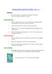
OPERATING INSTRUCTIONS W1411
OPERATING THE ALARM
1.
To set the alarm, Place the Normal / Set Switch into the Set Position.
2.
Turn the Alarm Set pot until the display shows the level at which you want
the alarm to sound.
3.
Replace the Normal / Set Switch into the Normal Position.
When loading the vehicle, The alarm will sound when the display reaches the preset level.
The On / Off Switch can be used to silence the alarm when the level has been exceeded.
The Alarm will only sound with the Switch in the ON position.
Connector 8 Way
Alarm Override
Switch
Normal / Set
Switch
24V
0V
24V
0V
10V
0V
- IN
+ IN
Power
Cable
Alarm
Cable
Loadcell
Cable to
Junction
box
Brown
Blue
Brown
Blue
Brown
Blue
Black
White
+ Supply Side Lights
Ground of vehicle
+ Supply to Alarm
Ground to Alarm
10V Supply to cells
0V Supply to cells
- Signal from cells
+ Signal from cells
WELDING MAINTENANCE
Disconnect Power from Display when
undertaking any welding work.
Alarm level
Adjuster
LOADCELL MAINTENANCE
Regular checks that all Loadcell Mounting
Bolts are tightened to the correct torque are
essential.
JUNCTION BOX connections
O/S Front L/C
Cable to
Display
O/S Rear L/C
Terminal Strip
Browns from front cells & Cable to display - O O - Browns from back cells
Blues from front cells & Cable to display - O O - Blues from back cells
Blacks from front cells & Cable to display - O O - Blacks from back cells
Whites from front cells & Cable to display - O O - Whites from back cells
N/S Front L/C
N/S Rear L/C