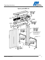
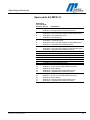
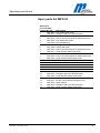
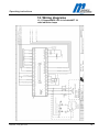
1
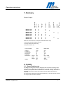
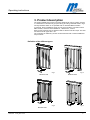
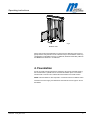
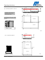
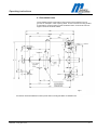
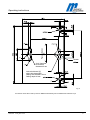
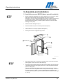
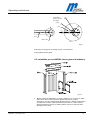
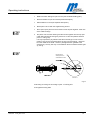
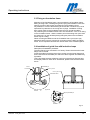
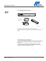
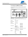
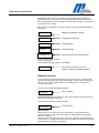
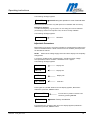
Operating instructions
Operating Instructions
Swing Door
Type MPG 12/22
Contents
1.
2.
2.1
2.2
2.3
2.4
3.
4.
4.1
5.
5.1
5.2
5.3
5.4
5.5
5.6
6.
7.
7.1
8.
9.
10.
11.
12.
13.
581E,5814 10.03_MPG 11/22
Delivery ...................................................................................2
Safety ......................................................................................2
General Safety Notes...............................................................2
Use for intended purpose ........................................................3
Identification of risks ................................................................3
Safety/Operation notes ............................................................3
Product description ...............................................................5
Foundation..........................................................................6–9
Foundation frame.....................................................................8
Assembly & installation ................................................ 10-14
Installation process MPG12 (above ground foundation) .......10
Installation process MPG22 (above ground foundation). ......11
Fixing on foundation frame ....................................................10
Installation of guide line with induction loops.........................13
Opening of the top cover .......................................................14
Assembly of roof with drain....................................................14
Electrical connection..................................................... 15-16
Locking unit..........................................................................17
Installation of locking discs ....................................................17
Commissioning ....................................................................18
Technical support ................................................................18
Spare parts and accessories ........................................ 19-22
Warranty................................................................................23
Control units.................................................................. .24-28
Wiring diagrams ............................................................. 29-39
1
Operating instructions
1. Delivery
Induction
loops
on both sides
Induction loop
Exit
X
X
X
X
X
X
X
X
X
X
X
X
Induction loop
Entry
X
X
X
X
X
X
X
X
Swing door
Pillar left
X
X
X
X
X
X
X
X
MPG12C-XX0
MPG12C-XX1
MPG12C-XX2
MPG12C-XX3
MPG22C-XX0
MPG22C-XX1
MPG22C-XX2
MPG22C-XX3
Pillar right
Upper housing
with cover
Scope of supply:
X
X
X
X
X
X
Electronic control unit MUC + SPS (NOT with MPG12/22C-XX0)
1 x Set of documents inside the top cover
1 x Fixing anchors (in Europe only)
2 x Keys for service door
Technical Data:
Type
MPG12/22
Voltage
Frequency
Current max.
Duty Cycle
Protection
Dimensions Length
Width
Height
Weight
VAC
Hz
A
%
IP
mm
mm
mm
Kg
230
50
2.0
100
54
645 – 2458
1451 – 1623
2234
250 Kg
2. Safety
2.1 General safety notes
The Magnetic swing door has been designed, built and tested according to the
latest technology. Although it has left the factory in a fully operational and safe
condition, it is important that the installation is carried out correctly. Therefore the
operating instructions must be read carefully and the safety notes must be
observed.
The manufacturer declines any liability and warranty in case of incorrect use and
use for purposes other than intended.
581E,5814 10.03_MPG 11/22
2
Operating instructions
2.2 Use for the intended purpose
The Magnetic swing door may be used only to control pedestrians entering or
exiting restricted areas, usually under surveillance. The wide construction of the
swing door allows taking along various objects, e.g. bicycles.
The Magnetic Universal Controller may be used only for controlling the Magnetic
swing door. Any other use is not permitted.
Conversions and modifications to the turnstile or to the control modules are not
permitted.
2.3 Identification of risks
Possible risks and notes are identified with the following symbols in the operating
instructions:
Warning!
This symbol in the operating instructions identifies actions and conditions that
can give rise to danger for life and limb of persons.
Observe the instructions carefully.
Caution!
All actions and conditions that can possibly give rise to damage to objects are
identified with this symbol in the operating instructions.
Observe the instructions carefully.
Note!
Relevant and useful notes for the user are identified with this symbol.
2.4 Safety notes
Disconnect all external opening or closing devices (remote control, control
desk, etc.) during maintenance work.
It is prohibited to install the barrier without proper mounting to the foundation.
A main power switch or residual current operated device is compulsory.
Risk of bodily harm while cover is open.
All swing doors require low maintenance.
An annual safety check has to be realized (see test book).
Documentation should be easily accessible.
Before commissioning make sure that all electrical and functional features are
tested.
The electrical wiring of the barrier must comply with the included drawings.
Only certified and trained electrical technicians may perform the electrical
connections.
581E,5814 10.03_MPG 11/22
3
Operating instructions
Only certified and trained electrical technicians may remove covers for mains
plug, mains receivers or wirings.
Before repairing electrical failures disconnect fuse.
Risk of bodily harm when closing the cover.
During maintenance work the fixing bolts must be checked and tightened, if
necessary.
Current carrying components like transformers, solenoids, resistors, stator
housings of motors, lamps etc. shall not be touched while in operation as the
warm temperature of the surfaces could cause burns.
Predictable fraudulent use may occur when somebody tries to pass the swing
door when it is closed or is beginning to close. Therefore, it is very important
that the operator makes sure that cyclists dismount their vehicles when
passing the swing door.
581E,5814 10.03_MPG 11/22
4
Operating instructions
3. Product description
The series of MPG swing doors have been designed to control cyclists, persons
in a wheelchair or similar user groups entering or exiting restricted areas in high
security situations which is not possible with our standard MPT turnstiles.
In principle, there is a MPG12 which can only be mounted in connection with a
MPT turnstile, and there is the MPG22 in „ stand alone „ version.
Each of both products may be delivered with or without induction loops. The door
movement of both types is 2 x 90°.
The controlling is realized by access control elements with or without additional
loop functions.
Definition of the different types:
Fig.1
MPG12C-XX0
Fig.2
MPG22C-XX0
Fig.3
MPG22C-XX1
581E,5814 10.03_MPG 11/22
Fig.4
MPG22C-XX2
5
Operating instructions
Fig.5
MPG22C-XX3
Above pictures show the definitions in respect to the different types (code of
types) and the entry direction to the induction loops. The definition of the loop
configuration is indicated in the fig. 2-5 (MPP22, definition XX0-XX2). MPG12
and MPG22 are identical in construction.
4. Foundation
A level concrete mounting surface is required to secure the turnstile housing.
For the dimensions, please refer to enclosed foundation plans. The cables
should finish a minimum of 5 meters above the finished concrete surface.
NOTE: This foundation is also required in connection with a foundation frame.
Conduits for mains supply and data lines should finish 50 mm approx. above
foundation.
581E,5814 10.03_MPG 11/22
6
Operating instructions
Conduit 25mm
Fig. 6 Foundation plan MPT 3x + MPG 12
5
Conduit 25mm
Concrete reinforcement
60
80
Concrete PZ 250
Conduit 25mm
Gravel, bed of drain
Foundation, smooth finish to be
positioned in water in a level
and horizontal manner
1.425
26
Lay separate conduits for power supply
and data cables, 50 mm approx. above
foundation.
Side of entry
Conduit 25mm
2.8
0
Conduit 25mm
Conduit 25mm
Side of exit
Side of exit
3.40
Fig.6
5
Abb. 7 Foundation plan MPG 22
Conduit 25mm
Concrete reinforcement
80
60
Concrete PZ 250
Conduit 25mm
Gravel, bed of drain
365
1.34
Side of entry
2.8
0
Conduit 25mm
Conduit 25mm
Side of exit
S id e o f e x it
581E,5814 10.03_MPG 11/22
Fig.7
1.90
7
Operating instructions
4.1 Foundation frame
The foundation frame is required for swing doors to be mounted on a sub
ground, for example in case of paving stone. A level concrete mounting surface
is required for correct mounting of the foundation frame. It should be 150 mm
approx. below the finished surface.
5
Fig.8
The sketch shows the different location points when mounting the MPG 12 with MPT 3X
581E,5814 10.03_MPG 11/22
8
Passage direction
Operating instructions
Conduit
Only ifrequired:
2nd conduit
diametre 25 mm
Anchor bolt dowel (F)
with inside thread M10
Drilling hole diametre 16 mm
Drilling depth 90 mm
Fig. 9
The sketch shows the location points for MPG22 alternatively also available with induction loops
581E,5814 10.03_MPG 11/22
9
Operating instructions
5. Assembly and installation
5.1 Installation process MPG12 (above ground foundation)
•
Before starting the installation you have to determine or to ensure on which
side is the entry and exit of the door (please see point 3, product
description). It is very important that the service door is always located at the
so-called “secure area”. After this determination parts 2 and 3 shall be
aligned respectively and be put aside (rotation centre is on left side when
standing at entry side).
•
Make foundation drillings for part 3.
•
Mount threaded rod (see enclosed separate description).
•
Wait till bolts are cured (see separate description).
•
Mount part 3 with the supplied fixing screws.
Cover
1
Upper housing
2
4 Connection piece
Base for door
3
5 Door
optionally with
induction loop
optionally with
induction loop
5977,5030 Version 1 KF 14.07.2004
Fig.10
581E,5814 10.03_MPG 11/22
•
Place part 2 upon part 3, mount the connection piece 4 and then screw all
parts together. Take care of the cable bushing!!
•
Put part 5 over the lower bearing and then screw together from the top part
5 with plain washers and flange by means of 4 x M16 x40 (Please observe
point 7: Locking unit).
It is very important to pay attention that the motor flange is in the correct
position. This can be recognized when the key slot of the flange - observed
from the middle of the shaft - shows in passage direction (parallel to the
closed door). The key slot may not be between the drive shaft and base (part
3), see fig.
10
Operating instructions
Pay attention to
position of the slot
in the flange
Flange
Door
Door
Base for door
Detail A
T
Fig.11
● Mounting of locking unit according to point 7: Locking unit
● Now tighten all fixing bolts
5.2 Installation process MPG22 (above ground foundation)
Fig.12
•
581E,5814 10.03_MPG 11/22
Before starting the installation you have to determine or to ensure on which
side is the entry and exit of the door (please see point 3, product
description). It is very important that the service door is always located at the
so-called “secure area”. After this determination parts 2, 3 and 4 shall be
aligned respectively and be put aside (rotation centre is on left side when
standing at entry side).
11
Operating instructions
•
Make foundation drillings for part 3 and 4 (see foundation/drilling plan).
•
Mount threaded rod (see enclosed separate description).
•
Wait till bolts are cured (see separate description).
•
Mount parts 3 and 4 with the supplied fixing screws.
•
Place part 2 upon parts 3 and 4 and then screw all parts together. Take care
of the cable bushing!!
•
Put part 5 over the lower bearing and then screw together from the top part
5 with plain washers and flange by means of 4 x M16 x40 (Please observe
point 7: Locking unit).
It is very important to pay attention that the motor flange is in the correct
position. This can be recognized when the key slot of the flange - observed
from the middle of the shaft - shows in passage direction (parallel to the
closed door). The key slot may not be between the drive shaft and base (part
3), see fig.
Bei Montage auf
Stellung der Nut im
Antriebsflansch achten
Türe
EINZELHEIT A
Fig.13
● Mounting of locking unit according to point 7: Locking unit
● No tighten all fixing bolts
581E,5814 10.03_MPG 11/22
12
Operating instructions
5.3 Fixing on foundation frame
Mounting of the foundation frame: correct positioning of foundation frame,
drilling of fixing holes, installing fixing bolts, laying the foundation frame into
water by means of jackscrews and tightening the foundation frame.
Pay attention to correct cable bushing to the turnstile. Conduits may not be
squeezed. Pay attention to the curing time of plugs. Installation of swing
door is then made on the foundation frame as on a normal foundation.
On positioning the foundation frame has to be considered – such as on fixing
on the foundation frame - that the rotation point of the swing door (view from
the entrance) is on the left side (the big triangular plate on the foundation
frame may be a help).
When mounting the MPG12 onto the foundation frame you have to pay
attention that the frame is mounted in connection with the MPT foundation
frame. This is important because both frames have to be screwed together.
5.4 Installation of guide line with induction loops
Description of installation procedure:
The lower flange is pre-mounted in our factory. Please check that the lower
flange can be moved.
Screw the guide line with the three fixing screws onto the lower flange and
then insert the three threaded pins and screw them together simultaneously,
if possible.
This is important because otherwise could occur that the two flanges have
an oblique position to each other. Afterwards, please make sure all screws
are fix.
Threaded pin
Screw
Lock washer
Base of guide line
Base of guide line
Foundation frame
DETAIL
B
(3x) Screw
(3x) Threaded pin
DETAIL
C
Fig.14
581E,5814 10.03_MPG 11/22
13
Operating instructions
5.5 Opening of the top cover
Cover
Side view
Upper housing
1. Unlock the lock and
take out the door
2. Remove screws
3. Remove the cover
Fig.15
5977 5031 V
i
1 KF 14 07 200 4
After opening of the lock and removal of both securing screws the cover can
be removed and put aside (please take care of possible damage of the
paint).
5.6 Assembly of roof with drain
As there are many different possibilities for assembly the documentation of
the roof with drain is added to each delivery as a separate mounting
instruction.
The roof with drain is not fixed to the MPG. Therefore, it has to be
considered as a product separated from the MPG. Only when using a
foundation frame there is a relation to the MPG.
581E,5814 10.03_MPG 11/22
14
Operating instructions
6. Electrical connections
Connection of mains supply should only be performed by a certified electrician
and according to the connecting diagram or after discussion with the supplier.
Fig.16
Connection unit with control unit MUC10 (Fig. 13 MPG 22)
Fig.17
581E,5814 10.03_MPG 11/22
15
Operating instructions
Connecting diagram
Fig.18 Connecting diagram MPG22 without induction loops
(further diagrams please see point 13).
581E,5814 10.03_MPG 11/22
Fig.18
16
Operating instructions
7. Locking unit für MPG 12/22
The swing door includes an electromechanical locking unit. This locking unit is
available in two different versions: In case of power failure it can either be turned
freely or remain locked. The locking discs required have to be assembled during the
mounting of the swing door (see below drawing).
Screw
Flange
Set screw
Locking disc
Screw
Locking disc
Lock washer
Flange
Distance bolt
Door
Door
Locking disc
Set screw
Distance bolt (4x)
Locking disc
Screw (4x)
Lock washer (4x)
Door
Screw
Pay attention to the
position of the cut out!
Screw
Door
Flange
Fig.19
7.1 Installation of locking discs
1.
2.
3.
581E,5814 10.03_MPG 11/22
Mount the swing door to the motor flange by means of 4 fixing screws.
Put the two locking discs on the distance bolts and pay attention that the
disc with the cut out shows in locking direction.
Insert the two hexagon socket screws (M6 x 12). The threaded pin that is
positioned opposite to the cut out serves the swing door as a final stopper.
It is pre-mounted in our factory.
17
Operating instructions
8. Commissioning
Once the mechanical and electrical installation of the swing door has been
completed, it can be put into service.
Check before start-up that all assembly and installation instructions have been
followed and the electrical connections have been performed correctly.
Once the voltage has been supplied and the safety device has been switched
on, the centre column rotates automatically in order to find the starting position
and to lock. Afterwards the centre column remains standing and is ready for
operation. During this rotation sounds a beep.
9. Technical Support
Should faults occur that could not be rectified by a technician, please contact our
authorised after-sales service representative.
In special cases, our Technical Support is available to you.
Please refer to the nameplate on the swing door housing for the data required in
the case of queries.
10. Spare parts and accessories
See Figure 18 for the exploded drawing which details the individual parts and
their identification numbers.
581E,5814 10.03_MPG 11/22
18
Operating instructions
Spare parts MPG 12
2059,5124 (gal
vanized)
2059,5144 (gal
vanized)
2059,5131 (gal
vanized)
without ind. loops
1031,5354 (gal
vanized) w. 2 ind.l.
1031,5355 RAL7042)w.
(
2 ind.l.
1031,5358 (1.4301)
w. 2 ind.l.
1031,5359 (1.4571)
w. 2 ind.l.
ind.loop on entry side
optionally
on entry andexit side
ind. loop on exit side
optionally
1031,5326 (gal
vanized)
on entry side
1031,5367 (gal
vanized)
on exit side
Fig. 20
581E,5814 10.03_MPG 11/22
19
Operating instructions
Spare parts list MPG 12
Small parts
(not indicated)
Position Art.-No.
1
3098,0025
1
3486,5013
2
3306,0007
2
3490,5003
2
3495,0006
2
3498,0020
5
3306,0033
5
3307,0008
5
3490,5003
5
3500,0014
7
3307,5000
7
3490,5009
7
3500,5000
7
3019,5008
8
3490,5010
9
3485,0043
9
3307,5000
10
3330,0014
11
3466,0019
12
3138,0040
13
3098,5000
13
3469,5017
13
3469,5018
13
3485,5018
13
3500,5006
14
3098,5000
14
3469,5017
14
3469,5018
14
3486,5016
14
3500,5006
581E,5814 10.03_MPG 11/22
Designation
Lock washer M16 (V2A)
Hexagon head screw M16x30 (V2A)
Hexagon nut M5 (brass)
Oval screw with hexagon socket M5x25 (V2A)
Lock washer M5 (V2A)
Disc M5 (brass)
Hexagon nut M5 (V2A)
Locknut M5 (V2A)
Oval screw with hexagon socket M5x25 (V2A)
Large diameter washer M5 (V2A)
Locknut M12 (V2A)
Oval screw with hexagon socket M12x60 (V2A)
Large diameter washer M12 (V2A)
Plain bearing
Screw DIN7991 M12x20 (V2A)
Screw DIN931 M12x50 (V2A)
Nut DIN985 M12 (V2A)
Rivet d3x8 (aluminium)
Key
Ground stud M8x8 (V2A)
Lock washer M10 (V2A)
Anchor rod of inside thread M10 (V4A)
Glass capsule
Hexagon head screw M10x55 (V2A)
Large diameter washer M10 (V2A)
Lock washer M10 (V2A)
Anchor rod of inside thread M10 (V4A)
Glass capsule
Hexagon head screw M10x40 (V2A)
Large diameter washer M10 (V2A)
20
Operating instructions
Spare parts MPG22
2059.5144 (gal
vanized)
without ind. loop
ind. loop on entry side
optionally
ind. loop on exit side optionally
1031,5362 (gal
vanized)
1031,5354 (gal
vanized) w. 2 ind.l.
1031,5355 RAL7042)w.
(
2 ind.l.
1031,5358 (1.4301)
w. 2 ind.l.
1031,5359 (1.4571)
w. 2 ind.l.
on entry side
on entry andexit side
1031,5367 (gal
vanized)
on exit side
Fig .21
581E,5814 10.03_MPG 11/22
21
Operating instructions
Spare parts list MPG 22
Small parts
(not indicated)
Position Art.-No.
1
3098,0025
1
3486,5013
2
3306,0007
2
3490,5003
2
3495,0006
2
3498,0020
5
3306,0033
5
3307,0008
5
3490,5003
5
3500,0014
7
3307,5000
7
3490,5009
7
3500,5000
7
3019,5008
8
3490,5010
10
3330,0014
11
3466,0019
12
3138,0040
13
3098,5000
13
3485,5018
13
3500,5006
14
3098,5000
14
3469,5017
14
3469,5018
14
3486,5016
14
3500,5006
581E,5814 10.03_MPG 11/22
Designation
Lock washer M16 (V2A)
Hexagon head screw M16x30 (V2A)
Hexagon nut M5 (brass)
Oval screw with hexagon socket M5x25 (V2A)
Lock washer M5 (V2A)
Disc M5 (Messing)
Hexagon nut M5 (V2A)
Locknut M5 (V2A)
Oval screw with hexagon socket M5x25 (V2A)
Large diameter washer M5 (V2A)
Locknut M12 (V2A)
Oval screw with hexagon socket M12x60 (V2A)
Large diametre washer M12 (V2A)
Plain bearing
Screw DIN7991 M12x20 (V2A)
Rivet d3x8 (aluminium)
Key
Ground stud M8x8 (V2A)
Lock washer M10 (V2A)
Hexagon head screw M10x55 (V2A)
Large diametre washer M10 (V2A)
Lock washer M10 (V2A)
Anchor rod of inside thread M10 (V4A)
Glass capsule
Hexagon head screw M10x40 (V2A)
Large diametre washer M10 (V2A)
22
Operating instructions
11. Warranty
The manufacturer reserves the right to adapt technological progress without
special announcement. Magnetic will be pleased to provide up to date
information and possible changes or additions to the operating instructions.
Under the precondition that the operating conditions are complied with, no
inadmissible interventions have been made to the interior of the equipment and
the equipment has no mechanical damage, a warranty of 2 year after delivery of
the equipment applies on all mechanical and electrical components.
581E,5814 10.03_MPG 11/22
23
Operating instructions
12. Control unit MUC 10-A100
The control unit MUC is mounted in a housing with 32 terminals. All terminals
are clearly marked for the connection to power supply and to the motor and
control inputs.
Abb.22
Supply voltage:
230 / 240V AC 50 Hz to terminals L-N-PE
Motor connection: The torque motor is to be connected to terminals M1- M2M3.
Locking:
Com 2 und Y 6
Motor braking:
Com2 und Y5
Locking:
Com2 und Y6
Relay outputs:
Home Position
On
Off
Alarm
Com1 und Y0
Com1 and Y1
Com1 und Y2
Com1 und Y3
Control inputs:
Single Output
Single Input
Bridge (Safety L + R)
Locking limit switch
Com4 und X3
Com4 und X4
Com4 and X5
Com4 und X6
For free entry and exit a permanent contact is required instead of an impulse
(bridge).
Manual Reset
Com4 and X7
Emergency unlocking
Com4 and X10
Encoder:
581E,5814 10.03_MPG 11/22
Encoder connections:
Com3
0vX0X1X2Shielding
brown
white
green
yellow
grey
Shielding
24
Operating instructions
The Magnetic MUC control unit is able to operate many Magnetic products.
Before leaving our factory all control units are adjusted for the operation of the
MPG. This adjustance is firmly programmed and will not change – not even after
an eventual loss of voltage.
After putting into operation the supply voltage the following message appears in
the display:
MPT 62
Magnetic Pedestrian Turnstile
240V50 Hz
Voltage and Frequency
© 2001
Copyright 2001
Ver 2.0
Version Number
STAND CLR
Swing door turns into Home Position
As soon as the swing door has reached its home position, it is stopped and
locks in this position.
The following message appears in the display:
* closed *
Swing door is locked in its home
position. Ready for standard operation.
Standard operation
Once received the entry/exit impulse, between 0.5 and 1 sec., the swing door
opens and the adjustable opening duration begins. After ending the swing door
returns to its home or original position. The rotating door can be stopped
manually at any time.
In this case the following message appears:
STALLED
Door is stalled.
Permanent Opening: Via bridging of one of the respective impulse entries the
door is set to Permanent Opening.
In this case the following message appears:
Held Open
Free entry/exit
Manual Reset:
Before leaving our company the control unit MUC is programmed with an
automatic Reset, i.e. after an eventual loss of voltage the door automatically
returns to operation.
Should you not wish this function the control unit could also be operated with a
manual reset, i.e. the MPG locks after return of voltage and waits for the manual
release impulse for putting into operation.
581E,5814 10.03_MPG 11/22
25
Operating instructions
The following message appears:
Pulse X7
Putting into operation in case of manual reset
Please activate this function only after previous consultation with our factory.
Emergency opening:
In cases of emergency, e.g. fire, panic, etc. the swing door can be released
(unlocked) by means of an impulse. Then, the door is freely rotatable.
The following message appears:
Unlocked
Unlocked
Adjustable Parameters
Before leaving our factory, the control unit MUC is programmed according to the
values as indicated below. If these values have to be modified, please proceed
as described as follows:
NOTE: Switch off the voltage supply and wait until the display has completely
extinguished.
1: Press the ‘ALTER‘ button. Simultaneously, actuate the supply voltage.
Hold pressed the buttons ‘ALTER‘ + ENTER for 3 sec. approx.
The following message appears:
Hardware
Display Info
MPT 62
Display Info
MPT 62
Display Info
BLT Unlock
Selection
Press again the „ALTER“ button and in the display appears „Blt Locked“.
Afterwards, press the „ENTER“-button.
Remove ARM
Deflt Yes
Turn the door in position Locked. Then
confirm by pressing ENTER.
Factory set selection
2: Press again the „ALTER“ button and in the display appears „Default No“.
Afterwards, press the „ENTER“-button.
581E,5814 10.03_MPG 11/22
26
Operating instructions
Confirm selection „No“
Press ENTER
Deflt No
3: Display message Auto Reset.
By pressing again the „ALTER“ button the display changes to „Manual Reset“.
Confirm the request by pressing the „ENTER“-button.
Auto Reset
Automatical Reset (factory setting)
Confirm with ENTER
Man. Reset
Manual Reset / Only after previous
consultation with our factory
4: Adjustance of H/Open (Hold Open time):
Adjustable by means of „ALTER“ button from 1 – 25 sec.
Confirmation of adjusted values by pressing the ENTER-button.
H/open:
4s
Open holding time (factory setting)
STEP 5: Adjustment of PE Dly (delay time of light barriers)
This time only has to be adjusted when light barriers or other components
regarding safety are installed. The PE Dly time causes that the swing door does
not immediately close after passing of the safety elements, but only when this
adjustable time has expired. This time can be adjusted between 1 and 25 sec.
The PE Dly time is independent from the open holding time. Choose the time by
pressing the ALTER button and confirm it with ENTER.
Display message:
PE Dly 0s
Delay time of light barrier
(factory setting)
6: Display-Message: Heat:
Adjustable by means of the button „ALTER“ in steps 0,1,2,3 .
Confirm the adjusted values with the button ENTER.
Adjustment instructions:
Outside temperature
> +10°C
-5° until +10°C
- 15°C until –5°C
- 15°C
Heating step
0
1
2
3
An activation of the heating effects a permanent current feed of the motor in the
Closed position (Home position).
6: Display-Message: save YES
If yes, press „ENTER“-button. If no, press „ALTER“-button again and then the
ENTER –button.
Start again with point 1.
581E,5814 10.03_MPG 11/22
27
Operating instructions
Save Yes
‘ENTER‘ for saving
Save No
‘ENTER‘ to reach again point 1
After saving the following display message appears:
Saved
MPG
New adjustments are saved
Magnetic Pedestrian Swing door
© 2001
Copyright 2001
Ver 2.0
Version Number
STAND CLR
The MPG turns into Home-Position
After reaching the Home-Position the following display message appears:
closed
The MPG is now ready for operation.
Address of Manufacturer
Magnetic Autocontrol GmbH
Grienmatt 20
79650 Schopfheim / Germany
Tel.
(49) 7622/695-5
Fax.
(49) 7622/695-603
[email protected]
www.ac-magnetic.com
581E,5814 10.03_MPG 11/22
28
Operating instructions
13. Wiring diagrams
13.1 Diagram MPG 12C–A1x3 with MPT 32
with induction loops
581E,5814 10.03_MPG 11/22
29
Operating instructions
581E,5814 10.03_MPG 11/22
30
Operating instructions
581E,5814 10.03_MPG 11/22
31
Operating instructions
581E,5814 10.03_MPG 11/22
32
Operating instructions
581E,5814 10.03_MPG 11/22
33
Operating instructions
13.2 Diagram MPG 12C–A1x3 with MPT 33
with induction loops
581E,5814 10.03_MPG 11/22
34
Operating instructions
581E,5814 10.03_MPG 11/22
35
Operating instructions
581E,5814 10.03_MPG 11/22
36
Operating instructions
581E,5814 10.03_MPG 11/22
37
Operating instructions
581E,5814 10.03_MPG 11/22
38