1
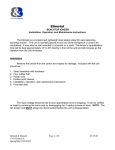
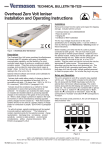
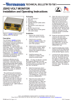
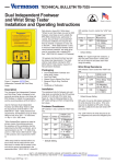
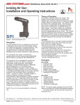
TECHNICAL BULLETIN TB-7525
Bench Top Zero Volt Ioniser
Installation and Operating Instructions
environment, it will be neutralised by
attracting opposite polarity charges
from the ionized air.” “Note that
ionization systems should not be used
as a primary means of charge control
on conductors or people.” (EN 613405-2 paragraph 5.2.9)
“As with all ionizers, periodic maintenance will be needed to provide
optimum performance.” “The following
list contains important points for the
selection process:- charge neutralisation; - discharge time; - ion balance; product sensitivity; - solution to static
problem; - environmental considerations, - airflow; - physical dimensions.”
(EN 61340-5-2 paragraph 5.2.9.2)
Figure 1. Vermason 200200 Bench Top
Zero Volt Ioniser
Description
The 200200 is a compact and lightweight
dual steady state DC auto-balancing
benchtop ioniser. The unit is normally
placed at one end of the workbench or
area to be neutralised. It may also be
wall mounted or mounted on a shelf. The
ionizer's neutralisation time will be best
approximately 30.48cm to 91.44cm
directly in front of the unit and will
increase as the distance from the unit
increases.
“Ionizers should be considered as a
method for charge neutralisation in
cases where grounding cannot be
achieved.” “Air ionization can
neutralise the static charge on
insulated and isolated objects by
producing separate charges in the
molecules of the gases of the
surrounding air. When a static charge
is present on objects in the work
Status of the unit can be monitored
remotely via the RS485 data ports.
Please contact the factory for the
necessary polling utility software.
Operation
Set the fan speed switch on the rear of
the unit to the LOW, MED, or HI position.
Higher airflow will result in faster
neutralisation rates. Position the unit so
that the maximum airflow is directed at
the items or area to be neutralised. Turn
the unit ON.
When the unit is first turned on, it
conducts a self-test. The audible alarm
will sound and then the LED will cycle
through RED, YELLOW, and then
GREEN. The LED will remain GREEN
during normal operation.
Installation
Balance Adjustment
Remove the ionizer from the carton and
inspect for damage. Included with the
unit should be:
The 200200 is an auto-balancing unit.
However, tuning or manual adjustment
can be accomplished by inserting a small
screwdriver or trimmer adjustment tool
into the balance adjustment hole located
on the right rear of the unit. To increase
the output in a positive direction, turn the
potentiometer in a clockwise direction.
Conversely, to increase the output in a
negative direction, turn the potentiometer
in a counter clockwise direction.
1
4
1
1
Stand assembly with hardware
Rubber feet
Emitter point cleaner
NIST Certificate
The input voltage should be set to your
specification prior to shipping. It can be
verified or reset by referring to the
Maintenance section of these
instructions.
Attach the stand to the unit by placing the
plastic spacers between the unit and the
stand and securing in place using the
knurled knobs. If desired, attach rubber
feet to each corner of the bottom of the
stand. Press feet firmly in place.
Before installing the unit, verify that the
AC outlet is properly connected to earth
ground. The unit must have a good earth
ground to maintain proper balance.
Figure 2. Area of Optimum Charge
Neutralisation
Made in America
Install the unit in the desired location,
making sure that the airflow will not be
restricted. Be sure the ON/OFF switch,
located on the rear of the unit, is in the
"OFF" position. Plug the power cord into
the unit and then into the appropriate AC
power source. This equipment has a
grounding type plug that has a third
(grounding) pin. This plug will only fit into
a grounding type power outlet. If the
plug does not fit into the outlet, contact
qualified personnel to install the proper
outlet. Do not alter the plug in any way.
Maintenance / Alarms
WARNING - RISK OF ELECTRIC
SHOCK - These servicing instructions
are for use by qualified personnel only.
To reduce the risk of electric shock, do
not perform any servicing of internal
parts unless you are qualified to do so.
The input voltage may be verified or
reset by removing the back case by
disengaging the 3 screws on back.
NOTE: The AC power cord MUST
always be disconnected before the unit is
disassembled.
Input voltage is selected with the two
internal jumpers as shown below:
Figure 3. 220 Volt Jumper Setting
UNIT C, 4TH DIMENSION, FOURTH AVENUE, LETCHWORTH, HERTS, SG6 2TD UK
Phone: 0044 (0) 1462 672005, Fax: 0044 (0) 1462 670440 • e-mail: [email protected], Internet: Vermason.co.uk
TB-7525 December 2008 Page 1 of 2
© 2008 Vermason
If the supply voltage drops from 200 Volts
to below 170 Volts, the unit will shut down
the audible alarm will beep and the LED
will blink RED. The unit will automatically
reset when the minimum voltage is
restored.
Under normal conditions, the ioniser will
attract dirt and dust (especially on the
emitter electrodes). To maintain optimum
neutralisation efficiency and operation,
cleaning should be performed on a
regular basis.
In the event of circuit failure, the unit will
enter shutdown mode.
When the unit enters shutdown mode,
ionisation will be stopped, the LED on the
front of the unit will change to a steady of
RED, and the audible alarm will sound
continuously. If the ioniser enters
shutdown mode, it must be turned OFF
and then back ON to reset the unit.
NOTE: The AC power cord MUST be
disconnected before the unit is
disassembled for maintenance. The
emitter electrodes should be cleaned
using the alcohol cleaners included or a
swab wet with Isopropyl alcohol. First,
turn the unit OFF and unplug the power
cord. Then remove the rear screen by
disengaging the 4 screws on back. After
cleaning the emitter electrodes, reattach
the rear screen using the 4 screws. Plug
in the power cord and turn the unit back
ON.
Figure 4. Decay time in seconds from 1000 volts to 100 volts on a 15.24cm x 15.24mm
charged plate per ANSI EOS/ESD S3.1.
Specifications
Air Flow
Three speed fan (125fpm -250fpm; 50100cfm).
Balance
±3 volt, typical; ±5 volts maximum.
(Temperature range: 18.33°C to 26.67°C,
R.H.: 15% to 65%)
Chassis
Stainless steel
Dimensions ( with stand )
24.13cm high x 15.24cm wide x 7.874cm
deep.
Emitter Points
.050" diameter pure tungsten for
improved mechanical strength and
ionization stability.
The emitter electrodes should not require
replacement during the life of the unit
with normal handling. Replacement
emitter electrodes can be ordered if
necessary.
Fuse
250 mA slow blow.
The best practice would be to verify the
balance of the unit with a charge plate
monitor after cleaning.
Input Power
AC line power, internally selectable for
220/230 VAC-50/60Hz.
Neutralisation (Decay) Times
Ion Emission
Steady state DC with sense feedback.
The comparative efficiency of benchtop
ionisers is determined by a standard test
published by the ESD Association:
Standard S3.1. Typical positive and
negative decay times (from 1000 volts to
100 volts) measured using this standard
are shown in Figure 4. The performance
of the ionizer was measured with the unit
positioned as shown, with the fan speed
on high, and without a filter.
High Voltage Power Supply
5.5 kV DC nominal.
Mounting
Bench top tilt adjust frame.
Ozone
Less than 0.05ppm
Weight
2.04 kg
NOTE: Unauthorized servicing or
modifications to your monitor will void the
product warranty and may create
dangerous conditions. Servicing should
be performed only at the factory, or by a
Vermason approved technician.
Limited Warranty
Vermason expressly warrants that for a period
of one (1) year from the date of purchase,
Vermason Bench Top Ionisers will be free of
defects in material (parts) and workmanship
(labour). Within the warranty period, a unit will
be tested, repaired or replaced at Vermason’s
option, free of charge. Call Customer Service
at 0044 (0) 1462 672005 for a Return Material
Authorisation (RMA) and for proper shipping
instructions and address. Any unit under
warranty should be shipped prepaid to the
Vermason factory. You should include a copy
of your original packing slip, invoice, or other
proof of purchase date. Warranty repairs will
take approximately two weeks.
If your unit is out of warranty, Vermason will
quote repair charges necessary to bring your
unit to factory standards. Call Customer
Service at 0044 (0) 1462 672005 for a Return
Material Authorisation (RMA) and proper
shipping instructions and address.
Warranty Exclusions
THE FOREGOING EXPRESS WARRANTY IS
MADE IN LIEU OF ALL OTHER PRODUCT
WARRANTIES, EXPRESSED AND IMPLIED,
INCLUDING MERCHANTABILITY AND
FITNESS FOR A PARTICULAR PURPOSE
WHICH ARE SPECIFICALLY DISCLAIMED.
The express warranty will not apply to defects
or damage due to accidents, neglect, misuse,
alterations, operator error, or failure to properly
maintain, clean or repair products.
Limit of liability
Electronic ionisers use high voltage corona
discharge and should not be used in or near
flammable or explosive environments. In no
event will Vermason or any seller be
responsible or liable for any injury, loss or
damage, direct or consequential, arising out of
the use of or the inability to use the product.
Before using, users shall determine the
suitability of the product for their intended use,
and users assume all risk and liability
whatsoever in connection therewith.
UNIT C, 4TH DIMENSION, FOURTH AVENUE, LETCHWORTH, HERTS, SG6 2TD UK
Phone: 0044 (0) 1462 672005, Fax: 0044 (0) 1462 670440 • e-mail: [email protected], Internet: Vermason.co.uk
TB-7525 Page 2 of 2
© 2008 Vermason