1
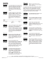
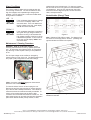
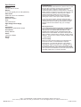
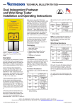
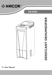
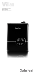
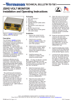
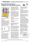
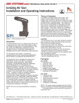
TECHNICAL BULLETIN TB-7529
Overhead Zero Volt Ioniser
Installation and Operating Instructions
Made in America
Installation
Remove the ioniser from the carton and inspect for shipping
damage. Included with the unit are:
1 Overhead Ioniser, Item 200300/200305
1 Keys (to power on)
1 Hanging Kit
1 Certificate of NIST Calibration
The AC input voltage should be set to the user's
specification prior to shipping (220v). It can be verified or
reset by referring to the Maintenance / Cleaning section of
these instructions.
Figure 1. Overhead Zero Volt Ioniser
Description
The Overhead Zero Volt Ioniser combines the effectiveness
of steady-state DC ionisation with ease of adjustability,
communication capability, and the flexibility of a microcontroller based design to produce a versatile and stable
ionisation system. Three fans produce extended ionisation
coverage, and are ideal for areas where bench space is
limited. (Note: for the 2 fan unit, disregard any instructions
relating to the 3 fan unit or fan 3.
Optional network software and remote control (200325) for
adjustments are available.
“Ionizers shall enable either polarity of charge on items to
be brought down and maintained to less than 100 V in
accordance with table 1 [To decay from 1 000 V to 100 V in
20 s maximum].” (EN 61340-5-1 paragraph 5.2.9)
“Ionizers should be considered as a method for charge
neutralization in cases where grounding cannot be
achieved.” “Air ionization can neutralize the static charge
on insulated and isolated objects by producing separate
charges in the molecules of the gases of the surrounding
air. When a static charge is present on objects in the work
environment, it will be neutralized by attracting opposite
polarity charges from the ionized air.” “Note that ionization
systems should not be used as a primary means of charge
control on conductors or people.” (EN 61340-5-2 paragraph
5.2.9)
“As with all ionizers, periodic maintenance will be needed
to provide optimum performance.” “”The following list
contains important points for the selection process: charge
neutralization; discharge time; ion balance; product
sensitivity; solution to static problem; environmental
considerations, airflow; physical dimensions.” (EN
61340-5-2 paragraph 5.2.9.2)
Before installing unit verify that the AC outlet is properly
connected to earth ground. The unit must have a good
earth ground to maintain proper balance. Install the unit in
the desired location, making sure that the airflow will not be
restricted through the unit. Make sure the ON/OFF key
switch, located on the side of the unit, is in the "OFF"
position. Plug the power cord into the unit and then into the
appropriate AC power source. This equipment has a
grounding type plug that has a third (grounding) pin. This
plug will only fit into a grounding type power outlet. If the
plug does not fit into the outlet, contact qualified personnel
to install the proper outlet. Do not alter the plug in any way.
Setup and Operation
The unit is powered on and off by using the keys supplied
with the unit. The key switch is located on the left end of
the unit along with the RS485 input/output ports for the
optional Zero Volt Ionizer software package. The control
buttons along with the LED display are located on the front
of the unit. The control buttons are numbered left to right as
shown in Figure 2. Button #1 ( ) corresponds to "Back",
button #2 ( ) corresponds to "Decrease", button #3 ( )
corresponds to "Increase" and button #4 ( ) corresponds to
"Forward".
When the ioniser is first powered on, the unit will display its
default address "000".
Figure 2.
UNIT C, 4TH DIMENSION, FOURTH AVENUE, LETCHWORTH, HERTS, SG6 2TD UK
Phone: 0044 (0) 1462 672005, Fax: 0044 (0) 1462 670440 • e-mail: [email protected], Internet: Vermason.co.uk
TB-7529 December 2008 Page 1 of 4
© 2008 Vermason
Setup Mode
O n
b
(Note: the control buttons can be
disabled, "OFF b", by the Item 200325
remote control only.)
P r o g
Press and buttons simultaneously to
get into the ioniser setup mode. When the
buttons are released, the unit should
beep once and "Prog" should appear
momentarily on the LED display. The
display will then move to the fan speed
settings.
To change the three digit network address and enable or
disable the remote control, use the following procedure.
Note: Address can only be 000 to 254. If an invalid
address is selected the display will blink, the buzzer will
sound three times, and the unit will not continue to other
menus until a valid address has been selected.
S P d 5
Press or buttons to adjust the fan
speed from "SPd 1" (lowest), to "SPd 9"
(highest) for operator comfort and
satisfactory decay times. Press the
button to go to the next menu. The next
menu is for the balance adjustment.
Starting with fan 1 and moving down to
fan 3.
1 2 3
Press and buttons simultaneously to
go into the ioniser setup mode.
S P d 5
The unit will display "Prog" momentarily
and go to the "fan speed" menu. Press
the button to go back to the "address"
menu.
1 2 4 A
The last digit of the address will be
flashing. Press or buttons to
change the last digit (0 to 9). Press the
button to go to the second digit of the
address.
Figure 3.
BA L1
Place the charge plate monitor under the
left fan (fan 1). Press and hold the
button (negative), or the button,
(positive), to adjust the balance under fan
1 to zero. For finer adjustment, use single
clicks of the buttons. Press the button
to go to the next fan. By pressing the
button you can go back to the previous
fan or menu.
1 5 4 A
The second digit of the address should
now be flashing. Press or buttons to
change the second digit (0 to 9). Press
the button to change the first digit of the
address.
2 5 4 A
B A L2
Move the charge plate monitor under the
middle fan (fan 2). Press
or
buttons to adjust the balance under fan 2
to zero. Press the button to go to the
next fan, or press the button to go to
previous menu.
B A L3
Move the charge plate monitor
under the right fan (fan 3). Press or
buttons to adjust the balance under fan 3
to zero. Re-check each fan and repeat
Bal 1, BAL2, and BAL3 adjustments as
necessary to eliminate the effect of airflow
interference between the fans. Press the
button to go to the next menu.
The first digit of the address will be
flashing. Press or buttons to change
the first digit (0 to 2). Press the button
to go to the enable or disable remote
menu.
O F F r
After pressing the button to get to the
enable or disable remote menu the display
will show "OFF r" for remote off (default
setting). This means that the unit will not
respond to the remote control. To enable
the remote, press the or buttons
until the display reads "On r" for remote
on.
S A VE
To save and exit at any time during the
setup mode press and buttons
simultaneously. The 200300/200305 will
save all settings and return to normal
operation. The 200300/200305 will
display "SAVE" and the status of the
buttons ("On b," meaning that the buttons
are enabled), then the unit address.
UNIT C, 4TH DIMENSION, FOURTH AVENUE, LETCHWORTH, HERTS, SG6 2TD UK
Phone: 0044 (0) 1462 672005, Fax: 0044 (0) 1462 670440 • e-mail: [email protected], Internet: Vermason.co.uk
TB-7529 Page 2 of 4
© 2008 Vermason
Alarm Conditions
The ioniser is able to detect various problems that may
occur through normal use. The unit can detect low and
high line voltages, and inoperable high voltage power
modules. The unit will sound a continuous audible alarm
during all alarm conditions.
AC
rubbing alcohol and a clean brush. To clean any excess
dirt off of the fan and or fan guard it is recommended to use
compressed air. Once the fan modules are clean slide
them back onto the alignment posts, connect the ribbon
cable, and replace the lid.
Neutralisation (Decay) Times
L
If the unit detects that the AC line voltage
is too low, it will display "AC L" and
sound the alarm. If the unit detects that
the line voltage is too high, it will display
"AC H" and sound the alarm.
S Hd 1
If the unit detects that there is something
wrong with the high voltage modules, or
the sensor circuitry, it will shutdown the
high voltage modules of the fan for which
it detected the problem. If this occurs for
fan #1 the unit will display "SHd 1" and
sound the alarm.
Figure 6.
Note: Reference ESD STM 3.1-2000. The distance from
the ioniser to the charge plate is 45.72cm. (Readings are
typical and taken at maximum fan speed.)
Maintenance / Cleaning Procedure
WARNING - RISK OF ELECTRIC SHOCK - These
servicing instructions are for use by qualified personnel
only. To reduce the risk of electric shock, do not perform
any servicing of internal parts unless you are qualified to
do so.
The AC input voltage can be verified or changed by
removing the top cover of the unit. The figures below show
the jumper (JH2) configuration for 220 VAC settings.
Figure 5. 220VA
(Note: the power cord MUST always be disconnected
before the unit is disassembled.)
To clean the ioniser first turn off and unplug the unit.
Remove the top lid by removing the six screws along the
top of the unit with a Phillips screwdriver. Once the lid is
removed the three fan modules are easily accessible. To
remove a fan module disconnect the ribbon cable
connector from the socket and lift the fan module out. The
eight emitter points can be easily cleaned using Vermason
part number 200155 emitter point tip cleaner, or 99%
Figure 7. Area of Optimum Charge and Neutralisation for
200300 and 200305
UNIT C, 4TH DIMENSION, FOURTH AVENUE, LETCHWORTH, HERTS, SG6 2TD UK
Phone: 0044 (0) 1462 672005, Fax: 0044 (0) 1462 670440 • e-mail: [email protected], Internet: Vermason.co.uk
TB-7529 Page 3 of 4
© 2008 Vermason
Specifications
Air Flow
100 cfm each of 3 Fans.
Balance
0V ±3 volt (typical), 0V ±5 volts (maximum.)
Dimensions
8.89cm D x 16.51 W x 106.68cm L
Emitter Points
Machined Tungsten
Fuse
400 mA slow blow
High Voltage Power Supply
5kV
Input Power
220/230V AC 50Hz Internal Jumper
Ion Emission
Steady State DC
Ozone
Less than 0.05ppm
Weight
4.5 kg
Limited Warranty
Vermason expressly warrants that for a period of one (1) year
from the date of purchase, Vermason Zero Volt Overhead
Ionizers will be free of defects in material (parts) and
workmanship (labor). Within the warranty period, a unit will be
tested, repaired, or replaced at our option, free of charge. Call
Customer Service at 0044 (0) 1462 672005 for a Return
Material Authorisation (RMA) and for proper shipping
instructions and address. Include a copy of your original
packing slip, invoice, or other proof of date of purchase.
If your unit is out of warranty, Vermason will quote repair
charges necessary to bring your unit up to factory standards.
Call Customer Service at 0044 (0) 1462 672005 for proper
shipping instructions and address. Ship your unit freight
prepaid.
Warranty Exclusions
THE FOREGOING EXPRESS WARRANTY IS MADE IN LIEU
OF ALL OTHER PRODUCT WARRANTIES, EXPRESSED
AND IMPLIED, INCLUDING MERCHANTABILITY AND
FITNESS FOR A PARTICULAR PURPOSE WHICH ARE
SPECIFICALLY DISCLAIMED. The express warranty will not
apply to defects or damage due to accidents, neglect, misuse,
alterations, operator error, or failure to properly maintain, clean
or repair products.
Limit of Liability
Electronic ionisers use high voltage corona discharge and
should not be used in or near flammable or explosive
environments. In no event will Vermason or any seller be
responsible or liable for any injury, loss or damage, direct or
consequential, arising out of the use of or the inability to use
the product. Before using, users shall determine the suitability
of the product for their intended use, and users assume all risk
and liability whatsoever in connection therewith.
UNIT C, 4TH DIMENSION, FOURTH AVENUE, LETCHWORTH, HERTS, SG6 2TD UK
Phone: 0044 (0) 1462 672005, Fax: 0044 (0) 1462 670440 • e-mail: [email protected], Internet: Vermason.co.uk
TB-7529 Page 4 of 4
© 2008 Vermason