1
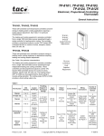
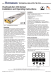
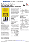
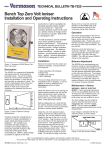
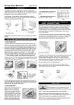
TECHNICAL BULLETIN TB-7561
ZERO VOLT MONITOR
Installation and Operating Instructions
Packaging
1
1
2
2
2
1
2
Figure 1. 222755 Continuous Dual
Operator Zero Volt Monitor
Description
The Vermason 222755 provides
continuous ground monitoring of
two operators and their workstations
using patented ZERO VOLT
MONITORINGTM resistive loop
technology. No other method is as
direct and reliable. This technology
allows the operator to typically
be near zero volts with respect to
Earth ground. The 222755 is also
unaffected by capacitance variations
associated with personnel and
environmental conditions.
Continuous Monitors pay for
themselves, improving quality,
productivity, eliminating wrist strap
daily testing and test result logging.
Reference EN 61340-4-1, per A.5.2
Measurement method for wrist
strap testing, “Where continuous
monitoring is used, no additional
testing is required.”
“The wrist band will normally be
worn for several hours at a time so
it needs to be comfortable while
making good contact with the
skin. It is a good idea to check the
wrist strap every time it is applied.
Constant on line monitors can be
used so that any breaks will be
immediately found.” [EN 61340-5-2
paragraph 5.2.7]
Zero Volt Monitor
Snap Kit
Wrist Strap Kits
Operator Ground Cables (black and white)
Mat Ground Cords (black and white)
Monitor Ground Cord
Floor Mat Ground Cords (green with yellow stripe)
TM
Installation
I. Remove the monitor from the carton and inspect for damage.
II. Determine the mounting location of 222755 monitor. The
front panel should be visible to
both of the operators.
III. Determine the mounting locations
of the operator remotes. Make
sure to place the remotes at a
distance that enables its leads to
reach the monitor.
IV. Install the remotes to the workbench or another surface using the provided screws.
Note: The Zero Volt MonitorTM remotes
are configured differently from other
Vermason remotes. Be sure to only use
the remotes that were packaged with
your Zero Volt MonitorTM.
V.
VI.
Made in America
VII. Attach the tinned wire end of the
black ground wire to the center
position on the screw terminal
block on the rear of the unit.
Attach the ring terminal end to
an alternate ground point. It is
important that this ground wire
is attached to a different ground
point than the mat ground cord of
the previous step. The face plate
screw of a grounded AC wall
outlet may provide a convenient connection point.
VIII. Route the hard-wired mat monitor
cords from the back of the
monitor to the snaps attached
to the grounded mats. Snap
the white mat ground wire to
the OPERATOR 1 mat and the
black mat ground wire to the
OPERATOR 2 mat.
IX. Insert the modular plugs of each
remote cord into their appropriate
modular jacks located at the rear
of the unit (See Figures 2 and 3).
X. Connect the DC power supply to
the power jack located at the rear
of the unit. Route the wire from
the supply to a nearby AC outlet
and plug the power supply into the
outlet. Make sure the voltage and
frequency match those listed on
the power supply. The monitor is
now powered.
Attach the tinned wire ends of
the mat cords to their appropriate
screw terminal block connection
located at the rear of the unit (See
Figures 2 and 3). The white cord
is for OPERATOR 1 and the black cord is for OPERATOR 2.
Attach the work surface mats to
ground using the mat ground
cords (See Figure 3). Attach the
ring terminal end of the cord to
the bench common ground point
or other appropriate ground point.
Attach the snaps at the opposite
ends of the cords to the snaps on
the work mat.
UNIT C, 4TH DIMENSION, FOURTH AVENUE, LETCHWORTH, HERTS, SG6 2TD UK
Phone: 0044 (0) 1462 672005, Fax: 0044 (0) 1462 670440 • e-mail: [email protected], Internet: Vermason.co.uk
TB-7561 April 2011 Page 1 of 5
© 2011 Vermason
NOTE: The operator remote has two
jacks. The 3.5 mm mono jack is to be
used for the dual wrist strap. A dual
operator wrist cord plugged into this
jack will be monitored. The banana
jack is grounded for use with a single
conductor operator wrist cord. This
is an unmonitored grounded guest
hookup.
Alarm Audible Adjust
Decrease CCW
Analog Output
Contact Manufacturer fo Specs
Data Output
Contact Manufacturer
Operator 1
White Cable
Power Connection
9-15VDC Center Positive
GND 1
Jumper JP1
Operator 2
Black Cable
Mat 1
White Wire
Earth Ground
Black Wire
Mat 2
Black Wire
GND 2
Jumper JP2
Figure 2. Rear View of the Zero Volt Monitor
TM
Charge Detection
When the operator is connected
to the remote and accumulates a
voltage greater than ± 1.25 volts, the
CHARGE LED (red) will display in
its respective OPERATOR section
(for charge detection data out, see
the Data Output section on Page
3). To disable charge detection
on the display, shunt jumper JP6
inside the unit (See Figurte 5). If a
charge is detected while using this
configuration, the display will remain
in its previous state until the charge
is no longer detected.
Alarm Indicators
Repetitive Single Beep
OPERATOR 1 / GROUND 1 Fail
Repetitive Double Beep
OPERATOR 2 / GROUND 2 Fail
Continuous Alarm
OPERATOR 1and OPERATOR 2 /
GROUND 1 and GROUND 2 Fail
10mm snap needs to pierce
and clinch bottom slide of mat
snap needs to be at least 12" apart
or 72" max
10mm snap needs to pierce
and clinch bottom slide of mat
snap needs to be at least 12" apart
or 72" max
Figure 3. Installing the Zero Volt Monitor
TM
Operation
Once Installation steps I - X have
been completed, the unit will be
monitoring the mats’ ground.
Then connect the operator wrist
straps and wrist cords by connecting
the dual snaps on the operator wrist
cords to the wrist strap, and the
mono plug at the other end of the
wrist cord into the operator remote
jack (See Figure 4). Monitoring
of the operators will remain in
the “STANDBY” position until an
operator’s wrist cord is plugged into
the remote jack.
Figure 4. Connecting the Operator Wrist Straps and Wrist Cords
UNIT C, 4TH DIMENSION, FOURTH AVENUE, LETCHWORTH, HERTS, SG6 2TD UK
Phone: 0044 (0) 1462 672005, Fax: 0044 (0) 1462 670440 • e-mail: [email protected], Internet: Vermason.co.uk
TB-7561 Page 2 of 5
© 2011 Vermason
The alarm volume may be adjusted
with the potentiometer located at
the rear of the unit. Adjust the
potentiometer counterclockwise to
decrease the volume. The volume
control may be disabled or enabled
by the jumper JP5 inside the monitor
(See Figure 5 for more details).
+ The Ground monitoring circuit not
only monitors your workstation ground,
but ensures a correct ground for the
operator. Therefore, if both grounds are
in the HIGH mode, your operators may
not be properly grounded.
Status Indicators
Audible Adjust Disable (Jumper JP5)
Standby condition: Operator not plugged into the remote.
Indicated by the blue LED in the
OPERATOR section of the display.
I. Remove the cover from the case.
Operator Fail High*:
Operator plugged into the remote and
the series resistance is greater than or
equal to 35M ohms (3.1M ohms operator
to ground). Indicated by the red LED in
the OPERATOR section of the
display as well as an audible alarm.
Operator Pass Safe*+:
Operator plugged into the remote and
the series resistance is within the range
of 1.9M ohms (975k ohms operator
to ground) to 35M ohms (3.0M ohms
operator to ground). Indicated by the
green LED in the OPERATOR section of
the display.
Operator Fail Low*:
Operator plugged into the remote and the series resistance is less
than or equal to 1.70M ohms (925k
ohms operator to ground). Indicated
by the yellow LED in the OPERATOR
section of the display as well as an
audible alarm.
Ground Fail High*:
The series resistance from the mat
connection to ground and back to the
circuit is greater than 3.8M ohms or 3
ohms (depending on the configuration).
Indicated by the red LED in the
GROUND section of the display as well
as an audible alarm.
JUMPER SETTINGS
II. Remove jumper JP5 (See Figure 5) to enable the Audible Adjust Potentiometer located at the rear of unit, or add the jumper to disable it (maximum volume).
operator status to be sent out instead
of operator low status. To enable
charge detection data output, shunt
the jumper and choose “Zero Volt
MonitorTM Charge Detection Enabled”
as the device for this 222755. In
this configuration, an operator
“FAIL LOW” will be sent out as a
“PASS.” Contact the manufacturer
for additional information on the Data
Output.
Dimensions
Zero Volt MonitorTM:
14.3cm x 12.3cm x 6.1cm
Operator Ground Cable
Length: 365.8cm
Charge Display Disable (Jumper JP6)
Mat Ground Cord
Length: 182.9cm
I. Remove the cover from the case.
Monitor Ground Cord
Length: 182.9cm
II. Remove jumper JP6 (See Figure 5) to enable the Charge LED located on the front of the unit, or add the
jumper to disable the Charge LED.
Data Out with Charge (Jumper JP7)
I. Remove the cover from the case.
II. Remove jumper JP7 (See Figure 5) to disable the Charge Data Output for data collection, or add the jumper to enable the Data Output.
Specifications
Data Output
The 222755 has a data output on the
rear of the unit for operator and mat
status. Jumper JP7, located inside
the unit, enables charge detection
Floor Mat Ground Cord
Length:182.9cm
Calibration and Adjustments
CALIBRATION
The 222755 can be calibrated with
the 222770 Limit Comparator. This
will allow you to set the operator
series resistance pass high and low
limits. The factory default settings
are 35M ohms high and 1.9M ohms
low. Refer to the 222770 Limit
Comparator instruction manual for
more information
NOTE: The series “test” resistance
is not the same as the operator to
ground resistance. As shown in the
figure below, the series resistance is
made up of the 1M ohm resistors in
Ground Pass Safe:
The series resistance from the Mat
connection to ground and back to the
circuit is less than 3.5M ohms or 2
ohms (depending on the configuration).
Indicated by the green LED in the
GROUND section of the display.
* The resistances quoted above are the
Factory Defaults. These numbers will
vary depending on the configuration.
Figure 5. Jumpers JP1, JP2, JP5, JP6, JP7
UNIT C, 4TH DIMENSION, FOURTH AVENUE, LETCHWORTH, HERTS, SG6 2TD UK
Phone: 0044 (0) 1462 672005, Fax: 0044 (0) 1462 670440 • e-mail: [email protected], Internet: Vermason.co.uk
TB-7561 Page 3 of 5
© 2011 Vermason
skin contanct
resistance
1 Meg ohm
in cord
human body resistance
skin contanct
resistance
to monitor’s remote
1 Meg ohm
in cord
series resistance
Figure 6.
the cord, the wrist band to operator’s
skin resistance (skin contact
resistance), and the operator’s
resistance (human body resistance).
For a given series resistance, the
typical operator to ground resistance
can be calculated from the following
formula.
R operator to ground = (R series +
2M ohms) / 4
For a given operator to ground
resistance, the series resistance
can be calculated from the following
formula.
R series = (R operator to ground *
4) - 2M ohms
MAT RESISTANCE SETTINGS
3.5M ohm
I.
II.
If the desired resistance is 3.5M ohms, jumpers JP1
(GND 1) and JP2 (GND2), located at the rear of the unit, (See Figure 2) need to be on one pin.
High Resistance (10k ohms to
3.5M ohms)
I.
If the desired resistance is
high (10k ohms - 3.5M ohms), jumpers JP1 (GND 1) and JP2 (GND 2), located
at the rear of the unit, (See Figure 2) need to be on one pin.
II. Next, the desired resistance needs to be added in between the ground terminal and ground. Use a resistor sub box to accomplish this task.
III.
Connect the mat wire to the sub box and connect the sub box to ground.
IV.
Increase the resistance on the sub box to the desired level.
V.
Turn the appropriate pot (See Figure 7) counterclockwise until the GROUND FAIL (red LED).
VI. Slowly turn the pot clockwise until the GROUND passes (green LED).
VII. Add 10% more resistance (at least 1 ohm) to the resistance and see if the GROUND FAIL LED (red) turns on.
VIII. Return back to the starting resistance and confirm that the green LED turns back on.
NOTE: If the unit does not go red
with added resistance or return back
to green when the extra resistance is
removed, repeat steps V - VIII with
added care in turning the pot.
Low Resistance (< 1k ohms)
I.
If the desired resistance is low (< 1k ohms), jumpers JP1 (GND 1) and JP2 (GND 2), located at the rear of the unit, (See Figure 2) need to be on both pins.
II. Next, the desired resistance needs to be added in between the ground terminal and ground. Use a resistor sub box to accomplish this task.
III.
Connect the mat wire to the sub box and connect the sub box to ground.
The associated potentiometers need to be adjusted fully clockwise. The pots are located inside the unit on the bottom board. The potentiometer closest to the rear of the unit is for GND 1 and the one closest to the front of the unit is for GND 2 (See Figure 7).
Figure 7. GND 1 and GND 2 Potentiometers
UNIT C, 4TH DIMENSION, FOURTH AVENUE, LETCHWORTH, HERTS, SG6 2TD UK
Phone: 0044 (0) 1462 672005, Fax: 0044 (0) 1462 670440 • e-mail: [email protected], Internet: Vermason.co.uk
TB-7561 Page 4 of 5
© 2011 Vermason
IV.
Increase the resistance on the sub box to the desired level.
V. Turn the appropriate pot (See Figure 7) counterclockwise until the GROUND FAILS (red LED).
VI.
Slowly turn the pot clockwise until the GROUND passes (green LED).
VII. Add 10% more resistance (at least 1 ohm) to the resistance and see if the GROUND FAIL LED (red) turns on.
VIII. Return back to the starting resistance and confirm that the green LED turns back on.
NOTE: If the unit does not go red
with added resistance or return back
to green when the extra resistance is
removed, repeat steps V - VIII with
added care in turning the pot.
Limited Warranty
Vermason expressly warrants that for a period of five (5) years from the date of purchase,
Vermason Zero Volt Monitors will be free of defects in material (parts) and workmanship
(labor). Within the warranty period, a credit for purchase of replacement Vermason products,
or, at Vermason’s option, the product will be repaired or replaced free of charge. If product
credit is issued, the amount will be calculated by multiplying the unused portion of the
expected five year life times the original unit purchase price. Call our Customer Service
Department at 0044 (0) 1462 672005 for a Return Material Authorization (RMA) and
proper shipping instructions and address. Please include a copy of your original packing
slip, invoice, or other proof of date of purchase. Any unit under warranty should be shipped
prepaid to the Vermason factory. Warranty replacements will take approximately two weeks.
If your unit is out of warranty, Vermason will quote repair charges necessary to bring your
unit up to Vermason factory standards. Call Customer Service at 0044 (0) 1462 672005 for
proper shipping instructions and address. Ship your unit freight prepaid.
Warranty Exclusions
THE FOREGOING EXPRESS WARRANTY IS MADE IN LIEU OF ALL OTHER PRODUCT
WARRANTIES, EXPRESSED AND IMPLIED, INCLUDING MERCHANTABILITY AND
FITNESS FOR A PARTICULAR PURPOSE WHICH ARE SPECIFICALLY DISCLAIMED.
The express warranty will not apply to defects or damage due to accidents, neglect, misuse,
alterations, operator error, or failure to properly maintain, clean or repair products.
Limit of Liability
In no event will Vermason or any seller be responsible or liable for any injury, loss or
damage, direct or consequential, arising out of the use of or the inability to use the product.
Before using, users shall determine the suitability of the product for their intended use, and
users assume all risk and liability whatsoever in connection therewith.
UNIT C, 4TH DIMENSION, FOURTH AVENUE, LETCHWORTH, HERTS, SG6 2TD UK
Phone: 0044 (0) 1462 672005, Fax: 0044 (0) 1462 670440 • e-mail: [email protected], Internet: Vermason.co.uk
TB-7561 Page 5 of 5
© 2011 Vermason