1
 TECHNICAL BULLETIN TB-7564
ZVM LIMIT COMPARATOR
Operating Instructions
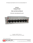
Figure 1. Vermason 222770 ZVM Limit Comparator
1. The purpose of the ZVM Limit Comparator is to verify the
calibration of the 222755 Zero Volt Monitor by checking
four operator conditions: FAIL LOW, PASS (low limit),
PASS (high limit), and FAIL HIGH.
2.
There are 10 resistor settings on the Limit Comparator,
which can be set using the rotary switch. Positions 3
through 8 have installed values. Positions 1, 2, 9, and 10
can be installed by the user for one set each of custom
low and high limits. The standard settings are as follows:
POSITION:
1.) optional low limit fail low
2.) optional low limit pass
-----------------------------3.) 1.91 Megohms FAIL LOW
4.) 1.91 Megohms PASS (ZVM default settings)
5.) 10 Megohms PASS
6.) 10 Megohms FAIL HIGH
-----------------------------7.) 35 Megohms PASS
8.) 35 Megohms FAIL HIGH
9.) optional high limit pass safe
10.) optional high limit fail high
PLEASE NOTE THAT THE ZERO VOLT MONITOR
OPERATOR LIMIT COMPARATOR IS USED TO
CHECK ONE OPERATOR AT A TIME
3. Ensure that the Zero Volt Monitor to be checked is
set up as described in the operating instructions and
has power.
4. Connect the plug from the limit comparator into the
OPERATOR 1 remote jack.
Made in the
United States of America
5.
Turn the rotary knob on the Limit Comparator to “x
Ohms LOW” (select x = 1.91 Megohms or the
optional low limit fail low, according to what operator
low limit the Zero Volt Monitor is calibrated).
Observe the operator 1 LED display on the front of
the Zero Volt Monitor. The yellow LED should be on
and the audible alarm should sound, indicating the
fail low condition.
6.
Turn the rotary knob on the Limit Comparator to “x
Ohms PASS” (select x = 1.91 Megohms or the
optional low limit pass safe, according to what
operator low limit the Zero Volt Monitor is calibrated).
The green LED on the Zero Volt Monitor operator 1
display should be on, indicating the low limit pass
safe condition.
7.
Turn the rotary knob on the Limit Comparator to “x
Ohms PASS” (select x = 10 Megohms, 35 Megohms
or the optional high limit pass safe, according to
what operator high limit the Zero Volt Monitor is
calibrated). The green LED on the Zero Volt Monitor
operator 1 display should be on, indicating the high
limit pass condition.
8. Turn the rotary knob on the Limit Comparator to “x
ohms HIGH” (select x = 10 Megohms, 35 Megohms
or optional high limit fail high, according to what
operator high limit the Zero Volt Monitor or is
calibrated). The red LED on the Zero Volt Monitor
operator 1 display should be on and the audible
alarm should sound, indicating the fail high condition.
9.
Disconnect the Limit Comparator plug from the
operator 1 remote jack. Plug the Limit Comparator
plug into the operator 2 remote jack and repeat the
four tests in steps 5 through 8 to test operator 2.
10. The correct color LEDs must light for each step for
the Zero Volt Monitor to completely pass the
calibration check. If an incorrect LED comes on
during any portion of the test (example: expecting
the green LED to light in step 7 but the Zero Volt
Monitor red LED is on) recalibrate the Zero Volt
Monitor and test each operator again with the Zero
Volt Monitor cal limit comparator.
INSTALLING OPTIONAL LOW AND HIGH LIMIT
RESISTANCES
A.) Use a hex wrench to remove the rotary switch
knob. Unscrew the 2 screws on the back of the unit
and disassemble the unit.
B.) Two resistances must be installed for each
limit: one for PASS and another for FAIL. These
two resistances should be ±10% of the calibrating
resistance. For example:
UNIT C, 4TH DIMENSION, FOURTH AVENUE, LETCHWORTH, HERTS, SG6 2TD UK
Phone: 0044 (0) 1462 672005, • E-mail: [email protected], Internet: Vermason.co.uk
TB-7564 Page 1 of 2 January 2014
© 2014 Vermason
LOW LIMIT
LOW LIMIT FAIL LOW LOW LIMIT PASS
CALIBRATION RESISTANCE
RESISTANCE
RESISTANCE [1M - (1M x 10%)]
[1M + (1M x 10%)]
1 Megohm
900Kilohms
1.1 Megohms
HIGH LIMIT PASS
HIGH LIMIT
RESISTANCE
CALIBRATION
[15M? - (15Megohms
RESISTANCE
x 10%)]
HIGH LIMIT
FAIL HIGH
RESISTANCE
[15Megohms +
(15M x 10%)]
15 Megohms
16.5 Megohms
13.5 Megohms
C.) The table below specifies which numbered
resistances on the circuit board correspond to the
optional low limit and the optional high limit. Solder
the appropriate resistors in these places.
D.) Assemble the unit and mark the appropriate places
on the label for the optional limits.
E.) It is recommended to turn the rotary switch to the
optional positions and measure the resistance from
the tip to the body of the plug with an ohmmeter to
verify the resistances.
NOTE: Two (three for position 10) resistor locations are
connected in series are provided in case resistors need
to be added to achieve the desired total resistance.
Solder a shorting wire across the resistor locations that
are not used.
MAINTENANCE
Wipe the plug periodically with alcohol.
Limited Warranty
Vermason expressly warrants that for a period of one (1) year
from the date of purchase, Vermason Limit Comparators will
be free of defects in material (parts) and workmanship (labor).
Within the warranty period, a credit for purchase of replacement
Vermason products, or, at Vermason’s option, the product
will be repaired or replaced free of charge. If product credit is
issued, the amount will be calculated by multiplying the unused
portion of the expected five year life times the original unit
purchase price. Call our Customer Service Department at 0044
(0) 1462 672005 for a Return Material Authorization (RMA) and
proper shipping instructions and address. Please include a copy
of your original packing slip, invoice, or other proof of date of
purchase. Any unit under warranty should be shipped prepaid
to the Vermason factory. Warranty replacements will take
approximately two weeks.
If your unit is out of warranty, Vermason will quote repair
charges necessary to bring your unit up to Vermason factory
standards. Call Customer Service at 0044 (0) 1462 672005 for
proper shipping instructions and address. Ship your unit freight
prepaid.
Figure 2.
Optional low limit
Designated resistors on circuit board
Low limit fail low
R1, R1A (*connected in series)
Low limit pass
R2, R2A (*connected in series)
Optional high limit
Designated resistors on circuit board
High limit pass
R9, R9A (*connected in series)
High limit fail high
R10, R10A, R10B (*connected in
series)
Warranty Exclusions
THE FOREGOING EXPRESS WARRANTY IS MADE IN LIEU
OF ALL OTHER PRODUCT WARRANTIES, EXPRESSED AND
IMPLIED, INCLUDING MERCHANTABILITY AND FITNESS
FOR A PARTICULAR PURPOSE WHICH ARE SPECIFICALLY
DISCLAIMED. The express warranty will not apply to defects or
damage due to accidents, neglect, misuse, alterations, operator
error, or failure to properly maintain, clean or repair products.
Limit of Liability
In no event will Vermason or any seller be responsible or liable
for any injury, loss or damage, direct or consequential, arising
out of the use of or the inability to use the product. Before using,
users shall determine the suitability of the product for their
intended use, and users assume all risk and liability whatsoever
in connection therewith.
UNIT C, 4TH DIMENSION, FOURTH AVENUE, LETCHWORTH, HERTS, SG6 2TD UK
Phone: 0044 (0) 1462 672005, • E-mail: [email protected], Internet: Vermason.co.uk
TB-7564 Page 2 of 2
© 2014 Vermason