Download Operating Instructions
Transcript
YILMAZ REDÜKTÖR ISO 9001 YILMAZ REDÜKTÖR ISO 9001 D Series Gear Units OIDCE0201-0814 Operating Instructions Operating Instructions D Series Contents Contents 1 How To Use This Manual............................................................................................ 04 2 Unit Designation....................................................................................................... 05 2.1 Detailed unit designation...................................................................................... 05 2.2 Nameplate unit designation................................................................................. 06 3 Part List of Standard Type Gear Units..................................................................... 07 3.1 D...00... Type................................................................................................... 07 3.2 D...01... Type................................................................................................... 08 3.3 D...02... Type................................................................................................... 19 3.4 D...03... Type................................................................................................... 10 3.5 D...0S...Type................................................................................................... 11 3.6 D...0E... Types................................................................................................ 12 3.7 D..4 Additional Stage...................................................................................... 13 3.8 D..5 and D..6 Additional Stages...................................................................... 15 3.9 D Series Motor Flange for Direct Coupled Types........................................... 15 3.10 DN..., DV...Types B5, B14 Motor Flange....................................................... 15 3.11 DT... Types Input Bearing Housing with Solid Input Shaft............................. 16 4 Safety.......................................................................................................................... 18 4.1 Intended Use...................................................................................................... 18 4.2 Improper Use..................................................................................................... 18 4.3 Safety Instructions............................................................................................. 19 4.3.1 General Safety Instructions.................................................................... 19 4.3.1.1 Working on the gear reducer....................................................... 19 4.3.1.2 Operation.................................................................................... 19 4.3.1.3 Maintenance............................................................................... 19 4.3.1.4 Lubricant.................................................................................... 19 4.3.1.5 Ambient Conditions.................................................................... 19 4.4 Tightening Torques............................................................................................. 20 4.5 Case of Fire....................................................................................................... 20 4.5.1 Suitable extinguishing agents, protective equipment.......................... 20 4.5.2 Unsuitable extinguishing agents......................................................... 20 5 Thinks to Check Before the Gear Unit or Geared Motor is Installed..................... 21 5.1 Transportation.................................................................................................. 21 5.2 Storage............................................................................................................ 22 6 Installing The Gear Unit............................................................................................. 23 6.1 Before you start.................................................................................................. 23 6.2 Check the shaft dimensions to fit....................................................................... 23 6.3 Check the ambient temperature......................................................................... 23 6.4 Check the voltage supply................................................................................... 26 6.5 Check the mounting position.............................................................................. 26 6.6 Use the breather plug........................................................................................ 26 6.7 Check the oil level.............................................................................................. 26 6.8 Check shaft ends and mounting faces............................................................... 26 6.9 Cover abrasive ambient..................................................................................... 26 6.10 Check accessibility to filling, breather and drain plugs.................................... 27 YILMAZ REDÜKTÖR 3 Operating Instructions D Series Contents 7 Mechanical Installation.............................................................................................. 27 7.1 Installing customer shaft with shoulder................................................................... 28 7.2 Installing customer shaft without shoulder.............................................................. 29 7.3 Disassembling customer shaft with shoulder......................................................... 30 7.4 Disassembling customer shaft without shoulder................................................... 31 7.5 Shaft tightening torques.......................................................................................... 32 7.6 Recommended shaft dimensions and disassembling nut dimensions.................... 33 7.7 Assembling customer shaft with shrink disk.......................................................... 34 7.8 Disassembling customer shaft with shrink disk...................................................... 36 7.9 Assembling gear unit with torque arm.................................................................... 37 7.10 Fitting output shaft elements................................................................................. 40 7.11 Correct position of output shaft elements............................................................ 40 7.12 Fitting couplings..................................................................................................... 41 8 Maintenance & Inspection......................................................................................... 42 9 Lubrication................................................................................................................. 43 9.1 Oil types................................................................................................................... 43 9.2 Changing the oil....................................................................................................... 43 9.3 Mounting Positions................................................................................................... 44 9.4 Oil Quantities........................................................................................................... 45 10 Troubleshooting Guide............................................................................................ 48 11 Disposal................................................................................................................... 51 11.1 Disposal of oil......................................................................................................... 51 11.2 Disposal of sealing................................................................................................. 51 11.3 Disposal of metal.................................................................................................... 51 12 Appendix................................................................................................................... 52 12.2 Warranty conditions................................................................................................ 53 12.3 Warranty.................................................................................................................. 54 12.4 Service Contact Points........................................................................................... 55 4 YILMAZ REDÜKTÖR 
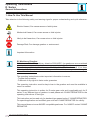
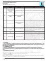
Operating Instructions D Series General Informations 1 -How To Use This Manual Take attention to the following safety and warning signs for proper understanding and quick reference. Electric Hazard; Can cause severe or fatal injuries. Mechanical Hazard; Can cause severe or fatal injuries. Likely to be Hazardous; Can cause minor or fatal injuries. Damage Risk; Can damage gearbox or environment. Important Information. EC Machinery Directive: Within terms of the EC machinery directive 2006/42/EC, the gearboxes are considered as not autonomous machine, but as a component to install in machines. Operation is prohibited within the area of validity of the EC directive, until it has been determined that the machine, in which this product is installed, corresponds to the regulations within this directive. The operating instructions contain important information to ensure; - Trouble-free operation - Fulfilment of any rights to claim under guarantee The operating instruction must be kept close to the gearbox and must be available in case it is needed. This operating instruction is written for D series gear units and is applicable only for D series. If any different type of gearbox is used please ask YILMAZ REDUKTOR for the operating instructions of that type. This instruction can be used only for standard type geared units of YILMAZ REDUKTOR. For special application and modified gear units ask YILMAZ REDUKTOR for validity. This manual does not cover 94/9/EC compatible gearboxes. For 94/9/EC contact YILMAZ REDUKTOR. YILMAZ REDÜKTÖR 5 Operating Instructions D Series Type Designation 2 -Unit Designation 2.1- Detailed unit designation Detailed D series gear units designation for ordering (This Designation is different from the short nameplate designation) D R 4 7 4 . 02 - 90S / 4 - L05 Brake L-220 V With Fan P-24 V With Fan S-220 V Without Fan Z-24 V Without Fan 01-10 Nm 02-25 Nm 04-40 Nm 05-50 Nm Motor Size For DV Types 90S / 4 Pole Number Frame Lenght Motor size 10-100 Nm 20-200 Nm 30-300 Nm 40-400 Nm For DN Types A06 :63 B5 B06 :63 B14 A07 :71 B5 B07 :71 B14 A08 :80 B5 B08 :80 B14 A09 : 90 B09 : 90 A10 :100 B10 :100 A11 :112 B11 :112 B5 B14 B5 B14 B5 B14 A13:132 B5 A25: 250 B5 B13:132 B14 A28: 280 B5 A16:160 B5 A31: 315 B5 A18:180 B5 A20:200 B5 A22:225 B5 Output Shaft 00:Hollow Shaft output 01:Solid Shaft Output 02:Solid shaft output with IEC B5 /14 Flange 03:Flanged and Hollow Shaft output 0S:Shrink Disk Output 0E:Extruder Output Stage 2 Stages 3 Stages 4 Stages 5 Stages 6 Stages Revision Number Housing Size 1...9 Input Type R : With Motor N :IEC B5 / B14 Flanged without Motor V:IEC B5 / B14 Flanged with Motor T:With Input Shaft Gearbox Type D Serie 6 YILMAZ REDÜKTÖR Operating Instructions D Series Type Designation 2.2- Nameplate, unit designation Nameplate unit designation is a short abbreviation from the detailed designation A sample name plate for D Series YILMAZ REDÜKTÖR www.yr.com.tr MADE IN TURKEY Type : DR473.03-90L/4 Serial N.: 100524545 Power : 1.5 kW Ratio: 116,6 Speed: 12 rpm. M. Pos.: M1 VG320 Oil Qty : 6.4 lt. Oil: ISO (Mineral Oil) Abreviations: Serial N. : Serial Number M.Pos. : Mounting Position Type Designation; DR473 - 100L/4 Type Motor Size DR-With motor DT- With input shaft DV- With Motor and IEC Flange DN- IEC Flange without Motor YILMAZ REDÜKTÖR 7 Operating Instructions D Series Part Designation 3- Part List of Standard Type Gear Units 3.1- D..00... Types for 2 and 3 Staged Gear Units 3 3 Only Valid For 3 Stages 1 31 30 35 34 29 32 33 2 24 25 18 19 20 21 22 23 26 27 28 3 11 9 8 7 3 6 5 4 10 12 17 16 15 14 13 Standard D...00... type basic part diagram. Parts may differ for special applications. Standard Part List 8 1- Pin Screw 9- Bearing 17- Seal 25- Gear 33- Bearing 2- Housing 10- Hollow Shaft 18- Closing Cap 26- Spacer 34- Circlip 3- Plug 11- Key 35- Closing Cap 19- Circlip 27- Bearing 4- Cover Plate 12- Gear 20- Spacer 28- Spacer 5- Screw 13- Spacer 21- Spacer 29- Bearing 6- Oil Seal 14- Bearing 22- Bearing 30- Gear 7- Circlip 15- Spacer 23- Shaft Gear 31- Key 8- Spacer 16- Circlip 24- Key 32- Gear YILMAZ REDÜKTÖR Operating Instructions D Series Part Designation 3.2- D..01... Types for 2 and 3 Staged Gear Units 3 3 Only Valid For 3 Stages 1 32 31 34 35 36 30 33 2 25 26 19 20 21 22 23 24 27 28 29 3 11 12 9 8 7 6 3 5 4 10 13 18 17 16 15 14 Standard D...01... type basic part diagram. Parts may differ for special applications. Standard Part List 1- Pin Screw 9- Bearing 17- Circlip 25- Key 33- Shaft Gear 2- Housing 10- Output Shaft 18- Oil Seal 26- Gear 34- Bearing 3- Plug 11- Key 19- Closing Cap 27- Spacer 35- Circlip 4- Cover Plate 12- Key 20- Circlip 28- Bearing 36- Closing Cap 5- Bolt 13- Gear 21- Spacer 29- Spacer 6- Oil Seal 14- Spacer 22- Spacer 30- Bearing 7- Circlip 15- Bearing 23- Bearing 31- Gear 8- Bearing 16- Spacer 24- Shaft Gear 32- Key YILMAZ REDÜKTÖR 9 Operating Instructions D Series Part Designation 3.3- D..02... Types For 2 and 3 Staged Gear Units 3 3 Only Valid For 3 Stages 1 34 33 37 38 36 32 35 2 27 28 21 22 23 24 25 26 29 30 31 3 11 12 9 8 7 6 3 5 4 10 13 18 17 16 15 14 19 20 Standard D...02... type basic part diagram. Parts may differ for special applications. Standard Part List 10 1- Pin Screw 10- Solid Shaft 19- Flange 28- Gear 37- Circlips 2- Housing 11- Key 20- Bolt 29- Spacer 38- Closing Cap 3- Plug 12- Key 21- Closing Cap 30- Bearing 4- Cover Plate 13- Gear 22- Circlip 31- Spacer 5- Bolt 14- Spacer 23- Spacer 32- Bearing 6- Oil Seal 15- Bearing 24- Spacer 33- Gear 7- Circlip 16- Spacer 25- Bearing 34- Key 8- Spacer 17- Circlip 26- Shaft Gear 35- Shaft Gear 9- Bearing 18- Seal 27- Key 36- Bearing YILMAZ REDÜKTÖR Operating Instructions D Series Part Designation 3.4- D..03... Types For 2 and 3 Staged Gear Units 3 3 Only Valid For 3 Stages 1 33 32 36 37 35 31 34 2 26 27 20 21 22 23 24 25 28 29 30 3 11 9 8 7 6 3 5 4 10 12 16 17 15 14 13 18 19 Standard D...03... type basic part diagram. Parts may differ for special applications. Standard Part List 1- Pin Screw 9- Bearing 17- Oil Seal 25- Shaft Gear 33- Key 2- Housing 10- Hollow Output Shaft 18- Flange 26- Key 34- Gear 3- Plug 11- Key 19- Bolt 27- Gear 35- Bearing 4- Cover Plate 12- Gear 20- Closing Cap 28- Spacer 36- Circlip 5- Bolt 13- Spacer 21- Circlip 29- Bearing 37- Closing Cap 6- Oil Seal 14- Bearing 22- Spacer 30- Spacer 7- Circlip 15- Spacer 23- Spacer 31- Bearing 8- Spacer 16- Circlip 24- Bearing 32- Gear YILMAZ REDÜKTÖR 11 Operating Instructions D Series Part Designation 3.5- D...0S... Types For 2 and 3 Staged Gear Units 4 4 Only Valid For 3 Stages 1 32 31 36 34 35 30 33 2 25 3 26 19 20 21 22 24 23 27 28 29 4 12 10 9 8 4 7 6 5 11 13 18 17 16 15 14 Standard D...0S... type basic part diagram. Parts may differ for special applications. Standard Part List 1- Pin Screw 12 9- Spacer 17- Circlip 25- Key 33- Shaft Gear 2- Shrink Disk 10- Bearing 18- Oil Seal 26- Gear 34- Bearing 3- Housing 11- Output shaft 19- Closing Cap 27- Spacer 35- Circlip 4- Plug 12- Key 20- Circlip 28- Bearing 36- Closing Cap 5- Cover Plate 13- Gear 21- Spacer 29- Spacer 6- Bolt 14- Spacer 22- Spacer 30- Bearing 7- Oil Seal 15- Bearing 23- Bearing 31- Gear 8- Circlip 16- Spacer 24- Shaft Gear 32- Key YILMAZ REDÜKTÖR Operating Instructions D Series Part Designation 3.6- D...0E... Types For 3 Staged Gear Units 2 9 1 3 4 9 5 6 8 7 10 11 12 Standard D...0E... type basic part diagram. Parts may differ for special applications. Standard Part List 1- Circlip 5- Extruder Neck 9- Key 2- Spacer 6- Bolt 10- Hollow Shaft Output 3- Flange 7- Seal 11- Spacer 4- Bolt 8- Bearing 12- Seal YILMAZ REDÜKTÖR 13 Operating Instructions D Series Part Designation 3.7- D..4 Series Additional Stage for 4 Stage Types 4 15 14 13 4 12 3 2 1 11 7 10 9 6 5 8 Standard D..4 type additional stage basic part diagram. Parts may differ for special applications. Parts List 14 1- Circlips 6- Circlips 11- Key 2- Bearing 7- Shaft 12- Key 3- Gear 8- Seal 13- Bolt 4- Oil plug 9- Gear 14- Additional Housing 5- Bearing 10- Circlips 15- Screw Pin YILMAZ REDÜKTÖR Operating Instructions D Series Part Designation 3.8- D Series 5-6 Stages Types N Type 2 and 3 stages are additional housing of D series 5 stages and 6 stages of gear units. 34 35 36 37 33 38 29 Only Valid For 6 Stages 31 30 25 26 27 32 28 23 17 22 15 20 18 14 24 8 21 19 6 5 4 3 2 1 7 16 9 12 13 11 10 Standard N type 3 stages basic part diagram. Parts may differ for special applications. Parts List 1- Housing 9- Gear 17- Key 25- Cover 33- Oil plug 2- Oil plug 10- Bearing 18- Seal 26- Circlips 34- Bolt 3- Circlips 11- Circlips 19- Circlips 27- Bearing 35- Eye bolt 4- Bearing 12- Cover 20- Bearing 28- Gear 36- Oil plug 5- Spacer 13- Output Flange 21- Spacer 29- Key 37- Top side cover 6- Gear 14- Bolt 22- Gear 30- Gear 38- Screw Pin 7- Bearing 15- Key 23- Bearing 31- Bearing 8- Key 16- Output Shaft 24- Circlips 32- Circlips YILMAZ REDÜKTÖR 15 Operating Instructions D Series Part Designation 3.9- D Series Motor Flange for Direct Coupled Types 10 Parts List 1- Shaft 6- Key 2- Circlips 7- Gear 3- Bearing 8- Circlips 4- Circlips 9- Nut 5- Flange 10- Key 9 1 4 8 7 6 2 3 5 3.10- DN..., DV...Types B5, B14 Motor Flange 10 Parts List 1- Shaft 6- Seal 2- Circlips 7- Gear 3- Bearing 8- Circlips 4- Circlips 9- Nut 9 1 4 5- B5 / B14 Flange 10- Key 8 16 7 6 3 2 5 YILMAZ REDÜKTÖR Operating Instructions D Series 3.11- DT... Types Input Bearing Housing with Solid Input Shaft Parts List 1- Seal 7- Circlips 2- Nut 8- Gear 3- Flange 9- Circlips 4- Shaft 10- Key 5- Bearing 11- Key 6- Bearing YILMAZ REDÜKTÖR 1 11 10 2 4 9 8 7 6 3 5 17 Operating Instructions D Series Safety 4- Safety 4.1- Intended Use The gear reducer is designed for use in industrial machines. Please refer to our catalogue or our web page for the maximum permitted torques and speeds. The most important maximum permitted values are indicated on the nameplate of the product. But the whole data can be found on our product catalogues. Using the product out of the product catalogue / nameplate’s permitted ranges will cancel the warranty/manufacturer declaration and YILMAZ will not take any responsibility. The gear units are intended for industrial machines and may only be used in accordance with the information provided in this manual the product catalogue and the nameplate of the gearbox. They comply with the applicable standards and regulations and meet the requirements of the directive 2006/42/EC. The gearbox must be started up, maintained and operated according this manual. The gearbox most be incorporated with 2006/42/EC confirming parts/machines. A motor connected to the gear unit is only allowed to be operated in the frequency entries so that the data provided on nameplate/catalogue of the gear unit is not exceeded and is accordance with the nameplate/catalogue. The speed range will be provided on the name plate if YILMAZ REDUKTOR is informed that the gear unit will be used with frequency inverter. If not informed the nameplate will have a single fixed speed and only this speed is allowed. The electric motor and frequency inverter must be in accordance with 2006/42/EC. If the gear units input is used with variable speed gear unit, this must be informed to YILMAZ REDUKTOR before ordering and on the nameplate the allowed maximum and minimum speeds (speed range) will be provided. If not mentioned by ordering the gear units speed will be a fixed single input speed and only this speed is allowed. If the gear unit will be driven by belt / coupling / chain drive etc. the gear unit is only allowed to be used according the nameplate/catalogue entries. Different speed, higher motor power, higher radial/axial loads etc. than nameplate/catalogue is not allowed. The ambient temperature must be between +5 - +40 ºC and no abrasive media must attack the paint and seals. If different working conditions this must be informed to YILMAZ before ordering. The gearbox maintenance (oil change / check ) must be done according this manual. 4.2- Improper Use Every usage which exceeds the limits stated above, the nameplate and catalogue of the product (especially higher torques and speeds) is not compliant with the regulations, and thus prohibited. The operation of the gear reducer is prohibited if; -It was not mounted/installed according to regulations and this manual -The gear reducer is very soiled -It is operated without lubricant -It is operated out of the permitted values provided on catalogues and/or nameplate. 18 YILMAZ REDÜKTÖR Operating Instructions D Series Safety 4.3- Safety Instructions 4.3.1- General Safety Instructions 4.3.1.1- Working on the gear reducer - Inappropriately executed work can lead to injury or damage. Make sure that the gear reducer is only installed, maintained and dismantled by trained technicians. - Foreign bodies spinning through the air can cause grave injury. Before putting the gear reducer into operation, check that there are no foreign bodies or tools near the gear reducer 4.3.1.2- Operation - Touching hot surfaces can lead to burns. Do not touch the gear reducer if their operation temperatures are too high, or use suitable safety equipment like gloves. -Rotating machinery can lead to injuries. There is danger of being trapped or pulled in! Keep a sufficient distance and make safeguarding to rotating machinery. See relevant norms EN349+A1, EN13857. 4.3.1.3- Maintenance -An unintentional start of the machine during maintenance work can lead to serious accidents. Make sure no one can start the machine while you are working on it. - Even a brief running of the machine during maintenance work can lead to accidents if the safety devices are not operating. Make sure that all safety devices are mounted and active. 4.3.1.4- Lubricant - Extended, intensive contact with oils can lead to skin irritations. Avoid extended contact with oil, and clean oil off skin thoroughly. - Hot oil can cause scalding. When changing oil, protect yourself against contacting hot oil. 4.3.1.5- Ambient Conditions - Standard gearboxes are allowed to work in ambient temperatures between +5 to +40 ºC unless differently specified on the nameplate. Using the gear unit out of this range can cause damage to the gear unit or environment. Over +40 ºC ambient conditions the gear unit surface temp could be so high causing burns when touched. -If the gear unit will be used in outdoor applications the gear unit must be prevented from rain snow and dust. Entering substances inside the gear unit from seals can damage the gear unit. Observe the safety instructions for outdoor use EN12100:2010 YILMAZ REDÜKTÖR 19 Operating Instructions D Series Safety 4.4- Tightening Torques All screwed connections for which a tightening torque is specified, must on principle be tightened with a calibrated torque wrench and checked. Use the following torques for the threaded bores over the gear unit housing. For connecting elements refer to the mechanical installation part. Bolt Size Class Tightenning Torque [Nm] M8 8.8 23 M10 8.8 43 M12 8.8 77 M16 8.8 190 M20 8.8 370 M24 8.8 640 4.5- Case of Fire The gear reducer itself is not combustible. However, it usually contains a synthetic or mineral gear oil. Please observe the following if the gear reducer is situated in a burning environment 4.5.1- Suitable extinguishing agents, Protective equipment Always keep suitable extinguishing, protective equipment like carbon dioxide, powder, foam, fog easily accessible around the gear unit. -High temperature produce irritating steam. Use a protective breathing apparatuses. 4.5.2- Unsuitable extinguishing agents Do not spray with water! 20 YILMAZ REDÜKTÖR Operating Instructions D Series Safety 5 -Thinks to Check Before the Gear Unit or Geared Motor is Installed If geared motors are used, please also refer to the manual of the motor manufacturer. Before you install the gearbox you have to be sure that the gearbox is arrived with the all necessary equipment and without damage. Points to take into consideration before you start to install the unit; - You have received the correct operation manual of the your product. - The gearbox and all its parts are transported without damage. - The gearbox is stored correctly according the instructions in this manual -You have the latest product catalogue or you have access to our web page 5.1- Transportation When the goods arrive, first check for any damage. If some damage observed, immediately contact the transport company and inform about the damage. Contact YILMAZ for the damage and do not start to install the unit until it is agreed that the damage has no affect of operation. Use the supplied eyebolts or lifting holes for lifting up the gear unit. The eyebolts are capable to carry the weight of gearboxes only. Do not hang additional loads. Use suitable hoisting equipment which is capable to hold the gear units weight. Refer to the catalogue for various types weights. See drawing bellow for hoisting point. Do not stay beneath / under the lifting/hoisting equipment which may cause serious injuries by falling down objects, accidental movements, unexpected accidents. Falling or hard placement can damage the gear unit. Only use hoisting and securing equipment which is permitted for the size / weight of your gear unit. Ensure that the load is slowly and carefully handled and placed. YILMAZ REDÜKTÖR 21 Operating Instructions D Series Checking 5.2- Storage If the geared unit or geared motor will be stored up to 3 years refer to the following instructions; With Packing; -Use corrosion protection oil for the output shaft and connection surfaces like flange surface or foot assembling surface. Seal the unit in a plastic wrap and pack it in container. A moisture indicator should be placed around the container to observe the moisture. Relative atmospheric humidity should not exceed 50%. The container should be kept under roof which protects from snow and rain. Under this condition the gear unit can be stored up to 3 year with regular check. The ambient temperature should be between -5 to 60 ºC. Without Packing; -Use protection oil for the output shaft and connection surfaces like flange surface or foot assembling surface. If no packing is used and the gearbox is stored without packing, the ambient temperature should be between 5 to 60 ºC. The gearbox must be kept under enclosed roof with constant temperature and constant humidity not exceeding 50%. The storage should be free of dust and dirt and ventilated with filter. If the gearbox is stored without packing it is recommended not to store more than 2 years and regular check during this time is recommended. If stored in open protect against insect damage. 22 YILMAZ REDÜKTÖR Operating Instructions D Series Checking 6- Installing The Gear Unit 6.1- Before you start; - Observe the gear unit for damages of storage or transportation. If any damage please contact YILMAZ REDUKTOR. - Be sure that you have all the equipment necessary for installing like; Spanners, torque wrench, shims and distance rings, fixing devices for input and output elements, lubricant, bolt adhesive etc. - This manual is not for 94/9/EC (ATEX) conforming gear units. For 94/9/EC conforming gear units refer to the ATEX range manual. ATEX conforming gear units have name plates indicating the zone and the temperature class and are different from standard type geared units. Therefore Standard units can not be installed on Potentially explosive atmospheres. 6.2- Check the shaft dimensions to fit; Output Shaft Type Hollow Shaft Hollow Shaft Output Shaft Tolerance (DIN748) Diameter Tolerance (H8) Diameter Up to 50mm k6 Over 50mm m6 D...172/173... D...272/273... D...282/283... D...372/373... D...472/473... 30 35 40 45 50 D...572/573... 60 D...672/673... 70 D...772/773... 90 D...872/873... 110 D...972/973... 120 +0.02 0 +0.03 0 +0.03 0 +0.03 0 +0.03 0 +0.03 0 +0.03 0 +0.04 0 +0.04 0 +0.04 0 30 35 40 40 50 60 70 90 110 120 +0.02 0 +0.02 0 +0.02 0 +0.02 0 +0.02 0 +0.03 +0.01 +0.03 +0.01 +0.04 +0.02 +0.04 +0.02 +0.04 +0.02 Flange Centering Shoulder Centering Shoulder Tolerance Diameter ( g6 ) 80 86 110 110 130 -0,01 -0,03 -0,02 -0,04 -0,02 -0,04 -0,02 -0,04 -0,02 -0,04 180 -0,02 -0,05 180 -0,02 -0,05 230 -0,02 -0,05 250 -0,02 -0,05 300 -0,02 -0,05 6.3- Check the ambient temperature; The ambient temperature must be between +5 ºC to +40 ºC for standard type gear units. If different contact YILMAZ REDUKTOR for special solutions. 6.4- Check the voltage supply; The standard geared motors are supplied with 230/400 V 50/60 Hz up to 3 kW including 3 kW and 400/690 V 50/60 Hz over 3 kW and is indicated on the motors name plate unless it is differently ordered. YILMAZ REDÜKTÖR 23 Operating Instructions D Series Installing In case of only gear unit is supplied from YILMAZ REDUKTOR please observe the name plate of the electric motor and the instructions of the supplier. Check the basic electric connection diagrams below. Use experienced electric technician. Using wrong connection or voltage can damage the electric motor or environment. The following wiring diagram is for standard 230/400 V 50 Hz AC electric motors. For different voltages please contact YILMAZ REDUKTOR. For gear units supplied without motor, refer to the motor manufacturers user manual. The electric connection must be done by experienced electric technician. The gearbox, the motor and the brake must be grounded to prevent potential differences of earth and gearbox/motor. Nominal Powers at 400V, 50Hz Pole Number 230V ( D ) / 400 V ( Y ) 400V ( D ) 2 or 4 ≤ 3 kW ≥ 4 kW 6 ≤ 2,2 kW ≥ 3 kW 8 ≤ 1,5 kW ≥ 2,2 kW Starting Principle Direct Direct or Y/D Basic motor connection wiring diagram L1 L2 L3 L1 L2 L3 U U U U (230V) (230V) (400V) (400V) I1 U U (230V) (400V) I3 I2 U2 I1 I3 I2 V1 V1 3 U1 V2 W2 L1 24 W1 U 3 V2 Iph= I Uph= Uph=U I ph =I W2 U2 W1 U1 W2 U2 V2 W2 U2 V2 U1 V1 W1 U1 V1 W1 L2 L3 L1 L2 L3 YILMAZ REDÜKTÖR Operating Instructions D Series Installing Standard type brakes basic wiring diagram The electric connection must be done by experienced electric technician. The gearbox and the motor must be grounded to prevent potential differences of earth and gearbox/motor. Gecikmeli Frenleme / Delayed Running Brake / Verspätete Bremsung ( 220 V) Ani Frenleme / Sudden Brake / Plötzliche Bremsung (220 V) R S T N R S T Fren Bobini Fren Bobini M M 3 3 Gecikmeli Frenleme / Delayed Running Brake / Verspätete Bremsung ( 24 V) R S T N M 3 YILMAZ REDÜKTÖR Fren Bobini Ani Frenleme / Sudden Brake / Plötzliche Bremsung (24 V) R S T N Fren Bobini M 3 25 Operating Instructions D Series Installing 6.5- Check the mounting position; The mounting position must be in accordance with the mounting position mentioned on the name plate. If different please contact YILMAZ REDUKTOR for possibilities of using in a different mounting position. Refer to the mounting positions and oil quantities on this manual and adjust the oil level accordingly with the recommended oil types given on this manuel. Do not mix synthetic oils with mineral oils which can cause serious damage on the gear unit. 6.6- Use of breather plug; Breather plugs are not needed for D series under normal ambient and working conditions (Up to 30 ºC ambient temperature and up to 8 hours per day) . If heavy ambient conditions and long time working hours then breather plug are recommended by YILMAZ REDUKTOR and delivered with the gearbox together. Replace the breather plug with the most top plug according to your mounting position. Some plug positions are not machined according mounting position. If no mounting position is mentioned by ordering, the standard M1 position plugs are machined. 6.7- Check the oil level ; On the mounting position tables the oil level plug is shown. Please refer to those tables and be sure that the oil level is correct according the mounting position by screwing half way out the level plug and see if oil comes out from that plug. If oil comes out tighten the plug again. If no oil comes out take out the filling plug and add oil until oil comes out from the level plug and tighten both plugs after finish. Be sure you are using the correct oil mentioned on the oil tables on this manual. Do not mix synthetic oils with mineral which can cause serious damage on the gear unit. 6.8- Check shaft ends and mounting faces; Before you start to installing be sure that all the connection elements are free of oil and dust. The output shaft may be protected by anti-corrosion oil. Please remove this using available solvents on your market. By using this do not touch sealing lips or painting of the housing. 6.9- Cover abrasive ambient; If the gear unit will be placed on a abrasive ambient be sure that the output seals are covered so that no abrasive material, chemicals or water touches the seals. Any pressure coming from outside over the seals can cause that the out staying substances to enter the gearbox and cause serious damage to the gear unit. If pressure or abrasive material can not be prevented from coming over the sealing, contact YILMAZ REDUKTOR for solutions. Abrasive material, chemicals, water, positive or negative pressure exceeding 0,2 bar can affect or damage the sealing lip or output shaft. Inside entering substances from the seals can cause serious damage to the gear unit. 26 YILMAZ REDÜKTÖR Operating Instructions D Series Installing 6.10- Check accessibility to filling, breather and drain plugs; The filling, breather and drain plugs must be freely accessible for further checking and service. 7- Mechanical Installation The gear unit can only be installed using the supplied connection points like foot and flange assembling points. To install the gear unit without the supplied connection points can cause serious injuries by loosening or braking the gear unit. Even the gear unit is installed totally correctly according this manual, be sure that no one will be harmed by accidentally brake downs or loosening. The mounting plate must be rigid enough not allowing torsions, flat enough to prevent strains by tightening the bolts and stable enough not allowing vibrations. By using chain drives this becomes much more important because of the polygon effect on chain drives. According to your connection elements the maximal permitted radial and axial load of the gear unit must be in accordance with your application. Check the product catalogue for permitted radial loads and calculation. If the output or input shaft is overloaded by radial or axial loads it can cause serious damage to the gear unit. Secure the gear unit using 8.8 or higher quality bolts. Cover all the turning parts from human entering or touching. Turning parts can cause severe or fatal injuries. For different kind of basic installations refer to the following illustrations. YILMAZ REDÜKTÖR 27 Operating Instructions D Series Installing 7.1- Installing customer shaft with shoulder 7.1.1- Use anti-seize assembling paste available on your market. Use a brush to apply the paste. 7.1.2 -Fasten the bold as shown below. 1 2 3 4 5 1 23 6 1- Retaining Bolt 2- Lock Washer 3- Washer 4- Circlip 5- Hollow Shaft 6- Customer Shaft 4 5 6 28 YILMAZ REDÜKTÖR Operating Instructions D Series Installing 7.2- Installing customer shaft without shoulder 7.2.1- Use anti-seize mounting paste available on your market. Use a brush to apply the paste. 7.2.2 -Fasten the bold as shown below. 1 2 3 4 5 1 23 6 1- Retaining Bolt 2- Lock Washer 3- Washer 4- Circlip 5- Hollow Shaft 6- Customer Shaft 4 5 6 YILMAZ REDÜKTÖR 29 Operating Instructions D Series Installing 7.3- Disassembling customer shaft with shoulder 7.3.1- Disassemble the bolt and take out the parts as shown 1 23 4 5 6 7.3.2 -Use the disassemble set from YILMAZ and fasten the bold as shown bellow to take out the output shaft. For disassemble sets look the following pages. 1 2 3 4 5 6 1 2 3 1- Retaining Bolt 2- Circlip 3- Lock Washer 4- Washer 5- Hollow Shaft 6- Customer Shaft 4 5 6 30 YILMAZ REDÜKTÖR Operating Instructions D Series Installing 7.4- Disassembling customer shaft without shoulder 7.4.1- Disassembly the bolt and take out the parts as shown 1 2 3 4 5 5 6 7.4.2 -Use the disassembly set from YILMAZ and fasten the bold as shown bellow to take out the output shaft. For disassembly sets look the following pages. 1 2 3 4 5 6 1 2 3 1- Retaining Bolt 2- Circlip 3- Lock Washer 4- Washer 5- Hollow Shaft 6- Customer Shaft 4 5 6 YILMAZ REDÜKTÖR 31 Operating Instructions D Series Installing 7.5- Shaft tightening torques Use the following table for shaft tightening torques. 32 Type Bolt Tightining Torque [Nm] D.172/173 M10 20 D.272/273 M12 20 D.282/283 M16 40 D.372/373 M16 40 D.472/473 M16 40 D.572/573 M20 80 D.672/673 M20 80 D.772/773 M24 200 D.872/873 M24 200 D.972/973 M24 200 YILMAZ REDÜKTÖR Operating Instructions D Series Installing 7-6 Advised Shaft Dimensions and Accessiories b (max) b1 b2 b3 c f t1 Ød1 m1 M e1 s Ød t k6 e 45° u g (DIN 332) h Type s u e1 t1 M d d1 m1 D.17.. 29.7 10 33 7.5 M12 30 29 D.27.. 34.7 12 38 9.5 M16 35 D.28.. 39.7 12 43 11.5 M20 D.37.. 39.7 12 43 11.5 D.47.. 49.7 12 53.5 13.5 D.57.. 59.7 16 64 17.5 M24 60 59 75 D.67.. 69.7 16 74.5 19.5 M24 70 69 D.77.. 89.7 20 95 24.5 M30 90 D.87.. 109.7 20 116 27.5 M30 D.97.. 119.7 20 127 31 M30 f b b1 b2 b3 c g h e t 36 89 50 20 19 1 M10 24 33 8 34 43 114 65 27 22 1 M12 30 38 10 40 39 50 124 69 28 27 2 M16 38 43 12 M20 40 39 50 138 75 35 28 2 M16 38 43 12 M20 50 49 60 165 87 41 37 3 M16 38 53.5 14 188 101 44 43 3 M20 44 64 18 85 248 115 78 55 4 M20 44 74.5 20 89 110 287 140 83 64 4 M24 52 95 25 110 109 130 347 165 98 84 4 M24 52 116 28 120 119 140 434 185 130 119 4 M24 52 127 32 5 Dismounting Mounting 6 Contour Bolt (DIN ISO 4014 . DIN ISO 4017) (DIN ISO 8765) YILMAZ REDÜKTÖR 33 Operating Instructions D Series Installing 7.7- Assembling customer shaft with shrink disk 7.7.1- Loosen the bolts of the shrink disk 7.7.2- Use a solvent available in your market to clean all the dirt an oil from the shaft and shrink disk hollow. The surfaces must be free from oil or any dirt. The solvent must be removed from the surfaces as well. 34 YILMAZ REDÜKTÖR Operating Instructions D Series Installing 7.7.3- Insert the shaft and tighten the bolts as shown. Be sure that there is a clearance between the shrink disk shoulder and the hollow shaft shoulder of the gearbox. 1 2 3 4 1- Customer Shaft 2- Bronze Ring 3- Hollow Shaft 4- Shrink Disk YILMAZ REDÜKTÖR Type Bolt Tightening Torque [Nm] D.1... M8 30 D.2... M8 30 D.3... M8 30 D.4... M8 30 D.5... M10 59 D.6... M10 59 D.7... M12 100 D.8... M14 160 D.9... M14 160 35 Operating Instructions D Series Installing 7.8- Disassembling customer shaft with shrink disk 7.8.1- Loosen the bolts of the shrink disk and take out the shaft. 36 YILMAZ REDÜKTÖR Operating Instructions D Series Installing 7.9- Assembling Gear Unit with Torque Arm 7.9.1- Use the torque arm connection according the following drawing. YILMAZ REDÜKTÖR 37 Operating Instructions D Series Installing 7.9.2- Assemble the parts as shown bellow 4 1 38 23 5 6 7 4 1- Bolt 4- Rubber Buffer 2- Washer 5- Bolt 3- Washer Ring 6- Fixing Plate 7- Bolt YILMAZ REDÜKTÖR Operating Instructions D Series Installing 7.9.3- For the fixing bold position refer to the following dimensions b b1 h1 Ød h YILMAZ REDÜKTÖR Type d b b1 h D.17. 17 54 27 158 D.27. 17 54 27 170 D.28. 17 54 27 198 D.37. 17 56 28 218 D.47. 22 80 40 278 D.57. 22 86 43 346 D.67. 26 110 55 395 D.77. 26 116 58 485 D.87. 32 160 80 550 D.97. 32 165 82.5 660 39 Operating Instructions D Series Installing 7.10- Fitting outputshaft elements Use the following illustration to assemble output shaft units 1) Gear shaft end 2) Thrust bearing 3) Coupling hub 7.11- Correct position of output shaft elements The Output Shaft unit (transmission elements) must placed as close as possible to the gear unit so that the radial load is as closest as possible to the gear unit. 1) Hub 40 YILMAZ REDÜKTÖR Operating Instructions D Series Installing 7.12- Fitting Couplings 7.12.1-By fitting couplings be sure that there is some clearance between the two elements 7.12.2-By fitting couplings be sure that there is no eccentric between the two shafts. 7.12.3-By fitting couplings be sure that the two shafts are not angular miss-aligned. YILMAZ REDÜKTÖR 41 Operating Instructions D Series Maintenance and Inspections 8- Maintenance and Inspections Under normal ambient and working conditions the gear unit should be checked according the following intervals. (For definition of normal working conditions refer to the product catalogue: “Selecting Gearbox” section); Item to check /replace Every 3.000 working hours or every 6 months Check for oil leakage x Check for oil level x Check oil leakage from seal x Check Rubber buffer Every 4.000 working hours Every 10.000 working hours or every 3 years Every 25.000 working hours x (Change if necessary) Check Bearings Noise x (Change if necessary) x (See Below for details) Change Mineral Oil Change Synthetic-PAO Oil x (See Below for details) Change Sealing x Change Bearing Grease x Change Bearings x Check for noise Changes x Oil change interval [Hours] 45000 40000 35000 30000 Mineral 25000 Synthetic PAO 20000 Synthetic PG 15000 10000 5000 0 70 80 90 100 110 120 130 140 150 160 Oil bath temperature (Celcius) For normal ambient conditions 70 ºC oil bath temperature should be taken as reference * For D series mineral oil is used unless it is differently ordered. For oil type and quantities refer to the following table. 42 YILMAZ REDÜKTÖR Operating Instructions D Series Lubrication 9- Lubrication 9.1- Oil Types Ambient Temp. [ºC] Lubricant DIN 51517-3 Aral Beyond Petroleum Castrol Klüber Lubrication Mobil Shell Total ISO VG Dip Lubrication Mineral Oil 0 ... +50 680 Degol BG 680 Energol GR-XP 680 Alpha SP 680 Klüberoil GEM 1-680 N Mobilgear XMP 680 Omala 680 Carter EP 680 -5 ... +45 460 Degol BG 460 Energol GR-XP 460 Alpha SP 460 Klüberoil GEM 1-460 N Mobilgear XMP 460 Omala F460 Carter EP 460 -10 ... +40 320 Degol BG 320 Energol GR-XP 320 Alpha SP 320 Klüberoil GEM 1-320 N Mobilgear XMP 320 Omala F320 Carter EP 320 -15 ... +30 220 Degol BG 220 Energol GR-XP 220 Alpha SP 220 Klüberoil GEM 1-220 N Mobilgear XMP 220 Omala F220 Carter EP 220 -20 ... +20 150 Degol BG 150 Energol GR-XP 150 Alpha SP 150 Klüberoil GEM 1-150 N Mobilgear XMP 150 Omala 150 Carter EP 150 -25... +10 100 Degol BG 100 Energol GR-XP 100 Alpha SP 100 Klüberoil GEM 1-100 N – Omala 100 Carter EP 100 CLP Food Grade Oil CLP NSF H1 -15 ... +25 320 – – Optileb GT 320 Klüberoil 4 UH1-320 N Mobil SHC Cibus 320 Cassida Fluid GL-320 Nevastane SL 320 Biodegradable Oil CLP E -25 ... +40 320 – – Tribol BioTop 1418-320 Klübersynth GEM 2-320 – – Carter Bio 320 Aralub HL3 Energrease LS 3 Spheerol AP3 Centoplex 2 EP Mobilux EP 3 Alvania RL3 Multis Complex EP 2 – Energrease SY 2202 – Petamo GHY 133 N Mobiltemp SHC 100 Cassida RLS 2 Multis Complex SHD 220 Mineral Grease [ -20 .... +120 Working Temperature ºC] Synthetic Grease [ -30 .... +100 Working Temperature ºC] 9.2- Changing the oil Refer to the nameplate to find out the correct oil filled inside the gearbox. -Do not mix synthetic oils with mineral oils which will cause serious damage to the gear unit. The oil change must be done by using the filling, draining and level plugs according the mounting position illustrated in section 9.4. - Extended, intensive contact with oils can lead to skin irritations. Avoid extended contact with oil, and clean oil off skin thorough. - Hot oil can cause scalding. When changing oil, protect yourself against contacting hot oil. YILMAZ REDÜKTÖR 43 Operating Instructions D Series Lubrication 9.3 Mounting Positions M1 M2 M5 Figured mounting positions of M1 to M6 are determined as reference of directional position of the gearbox. Mounting surfaces are not binding. M4 M6 M3 M1 M5 M2 Figured mounting positions of M1 to M6 are determined as reference of directional position of the gearbox. Mounting surfaces are not binding. M4 M6 M3 44 YILMAZ REDÜKTÖR Operating Instructions D Series Lubrication 9.4 Oil Plugs and Oil Quantities: D Series 2-3 Stage Oil Level Plugs: M1 M2 M4 M5 M3 M6 Oil Quantities (lt) Type M1 M2 M3 M4 M5 M6 DR172 1.3 1.5 1.0 1.4 1.3 1.4 DR173 1.0 1.3 0.8 1.1 1.2 1.1 DR272 1.9 2.2 1.4 1.8 2.0 2.1 DR273 1.8 2.0 1.2 1.6 1.6 1.9 DR282 2.4 3.2 2.0 2.7 2.8 3.0 DR283 2.0 2.8 1.8 2.1 2.2 2.4 DR372 3.0 4.2 2.4 2.6 3.8 3.9 DR373 3.2 3.7 2.0 3.5 3.3 3.5 DR472 6.8 7.0 4.6 6.0 6.0 6.2 DR473 6.4 8.4 5.5 5.0 7.2 7.3 DR572 11.4 12.7 8.6 11.4 10.0 11.0 DR573 11.2 12.4 7.4 9.6 11.5 11.35 DR672 19.0 20.0 15.1 16.0 19.5 19.5 DR673 18.0 18.0 14.0 15.0 15.0 16 DR772 29.0 30.0 22.0 24.0 25.0 27.0 DR773 27.2 28.0 20.0 22.5 22.0 24.0 DR872 46.0 48.0 39.0 38.0 42.0 44.0 DR873 43.0 45.0 32.0 36.0 40.0 42.0 DR972 78.0 81.0 59.0 64.0 75.0 78.0 DR973 73.0 76.0 54.0 61.0 70.0 73.0 ■ : Drain plug YILMAZ REDÜKTÖR ∆ : : Oil Filling and Vent plug ▲ Symbols : Oil level 45 Operating Instructions D Series Lubrication Oil Plugs and Oil Quantities: D Series 4 Stages Oil Level Plugs: B A A A B M1 B M3 M2 A B B A A B M6 M5 M4 Oil Quantities (lt) Type M1 A/B M2 A/B M3 A/B M4 A/B M5 A/B M6 A/B DR474 6.4/ 0.7 6.5 / 0.7 4.3 / 0.7 5.0 / 0.7 7.0 / 0.7 7.0/ 0.7 DR574 11.2 / 1.5 12.4 / 1.5 7.4 / 1.5 9.6 / 1.5 11.5 / 1.5 11.5 / 1.5 DR674 18.0 / 4.0 18.0 / 4.0 14.0 / 4.0 15.0 / 4.0 16.5 / 4.0 17.0 / 4.0 DR774 27.2 / 4.0 28.0 / 4.0 20.0 / 4.0 22.5 / 4.0 27.0 / 4.0 27.0 / 4.0 DR874 43.0 / 6.0 45.0 / 6.0 32.0 / 6.0 36.0 / 6.0 43.0 / 6.0 43.0 / 6.0 DR974 73.0 / 4.0 76.5 / 4.0 54.0 / 4.0 61.0 / 4.0 73.0 / 4.0 73.0 / 4.0 ■ : Drain plug ∆ 46 : : Oil Filling and Vent plug ▲ Symbols : Oil level YILMAZ REDÜKTÖR Operating Instructions D Series Lubrication Oil Plugs and Oil Quantities: D Series 5-6 Stages Oil Level Plugs: A B A A B B M2 M1 M3 B B A A B A M5 M4 M6 Oil Quantities. (lt) Type M1 A/B M2 A/B M3 A/B M4 A/B M5 A/B M6 A/B DR275 1.8 / 0.4 2.0 / 0.6 1.2 / 0.5 1.6 / 0.6 1.9 / 0.5 1.6 / 0.5 DR276 1.8 / 0.35 2.0 / 0.5 1.2 / 0.5 1.6 / 0.55 1.9 / 0.4 1.6 / 0.4 DR285 2.0 / 0.4 2.8 / 0.6 1.8 / 0.5 2.1/ 0.6 2.4 / 0.5 2.2 / 0.5 DR286 2.0 / 0.35 2.8 / 0.5 1.8 / 0.5 2.1 / 0.5 2.4 / 0.4 2.2 / 0.4 DR375 3.2 / 0.4 3.7 / 0.6 2.0 / 0.5 3.5 / 0.6 3.5 / 0.5 3.3 / 0.5 DR376 3.2 / 0.35 3.7 / 0.5 2.0 / 0.5 3.5 / 0.5 3.5 / 0.4 3.3 / 0.4 DR475 6.4 / 0.65 8.4 / 0.95 5.5 / 0.7 5.0 / 0.95 7.3 / 0.7 7.2 / 0.7 DR476 6.4 / 0.6 8.4 / 0.8 5.5 / 0.7 5.0 / 0.8 7.3 / 0.65 7.2 / 0.65 DR575 11.2 / 1.2 12.4 / 2.1 7.4 / 2 9.6 / 2.1 11.35 / 1.4 11.5 / 1.4 DR576 11.2 /1.1 12.4 / 2 7.4 / 1.9 9.6 / 2 11.35 / 1.3 11.5 / 1.3 DR675 18.0 / 1.2 18.0 / 2.1 14.0 / 2 15.0 / 2.1 16 / 1.4 15.0 / 1.4 DR676 18.0 / 1.1 18.0 / 2 14.0 / 1.9 15.0 / 2 16 / 1.3 15.0 / 1.3 DR775 27.2 / 2 28.0 / 3.4 20.0 / 3.1 22.5 / 3.4 24.0 / 2.8 22.0 / 2.8 DR776 27.2 / 1.9 28.0 / 3.3 20.0 / 3 22.5 / 3.3 24.0 / 2.6 22.0 / 2.6 DR875 43.0 / 2 45.0 / 3.4 32.0 / 3.1 36.0 / 3.4 42.0 / 2.8 40.0 / 2.8 DR876 43.0 / 1.9 45.0 / 3.3 32.0 / 3.0 36.0 / 3.3 42.0 / 2.6 40.0 / 2.6 DR975 73.0 / 4.5 76.0 / 8.0 54.0 / 7.5 61.0 / 8.0 73.0/ 5.5 70.0 / 5.5 DR976 73.0 / 4.0 76.0 / 7.6 54.0 / 7.0 61.0 / 7.6 73.0 / 5.0 70.0 / 5.0 ■ : Drain plug YILMAZ REDÜKTÖR ∆ : : Oil Filling and Vent plug ▲ Symbols : Oil level 47 Operating Instructions D Series Troubleshooting Guide 10- Troubleshooting Guide All the operations bellow must be done by authorized and skilled mechanician/electrician. Inform YILMAZ REDUKTOR before making any change to the gearbox. Only oil change is allowed to change without information. Do not make any think if you are not sure what you are doing and contact YILMAZ. Any change or operation done without the information of YILMAZ REDUKTOR is in your own risk and responsibility and YILMAZ REDUKTOR does not take any responsibility. ID 001 002 Problem Observation Remedy You hear no noise and shaft Please Check the voltage supply and frequency of your electric Gearbox Does Not is not turning. You are not connection. They must be in accordance with the nameplate of Start Up using any driver or frequency the motor. Observe motor manufacturers start up manual. Still inverter. does not work go to ID 100 You hear no noise and shaft Please observe the frequency incerter/driver manual. Chech is not turning. You are using the motor by supplying direct voltage to see if the problem is on frequency inverter or driver. your driver/frequency inverter. Still does not work go to ID 001. Gearbox Does Not Start Up Please Check the voltage supply and frequency of your electric connection. They must be in accordance with the nameplate of You hear some noise but both the motor. Observe motor manufacturers start up manual. Still 003 Gearbox Does Not Start Up motor shaft and gearbox shaft same problem, the load may be too high for the choosen motor. is not turning. You are not Loosen the gearbox from the load/torque. using any driver /frequency in- If it works than the starting torque is insufficient and higher moverter or braked motor. tor power is needed. For monophaze motors, check the starting up condansator and running condansator as well. If notting helps go to ID 100 You hear some noise but both 004 Gearbox Does Not motor shaft and gearbox shaft Start Up is not turning. You are using driver or frequency inverter. 005 Please observe the frequency inverters or drivers manual. To see if the problem is on your driver or frequency inverter take out the driver/frequency inverter and make direct voltage supply to the motor according the motors nameplate. Still does not work go to ID 100 Gearbox Does Not You hear some noise but both Please Check the voltage supply and frequency of your electric Start Up motor shaft and gearbox shaft connection. They must be in accordance with the nameplate of is not turning. You are using the motor. Observe motor manufacturers start up manual. Be braked motor sure that the brake is working. Observe the brake manufacturers manuel. If brake is supplied from YILMAZ observe this manuel for correct brake wiring diagram. If still not work supply the brake with voltage according its nameplate directly. For example 198V DC. You will hear a clicking noise explaining that the brake is opening. If you hear no noise the brake or rectifier is defect. If you hear the clicking noise the brake is working. You should this clicking noise by your normal electric connection as well. By supplying direct supply to the brake you hear the clicking noise and at same time you supply the motor with direct voltage according to its name plate and still same problem, the load may be too high for the choosen motor. Goto ID 003. 48 YILMAZ REDÜKTÖR Operating Instructions D Series Troubleshooting Guide ID Problem Observation Remedy For very low speeds the frequency inverters frequency is lowering down. For very low frequencies the inverter parameter and motor parameter Gearbox Does Not 006 Work in Low Speeds/ You are using frequencies. frequency inverter. must be optimized. Also for low speeds the efficiency of the gearbox may varry too much. Specially for worm-gearboxes. The recomended frequency range is 20-70 Hz for worm-gearboxes and 10-70 Hz for Helical Gear Boxes. Use Higher motor power and Frequency inverter or change ratio of gearbox to work inside the reccomended range. 007 Gearbox Does Not Start Mornings or After Long Time Stop. The oil is not in accordance with your working conditions. Change to loAmbient Temperature wer viscosity oils. Observe this manuel for using the correct oil. Working is below +5 Celsius in higher ambient temperatures is an other solution if possible. If still same problem you need higher motor power. Measure the surface temp. using a temperature measuring device under full load. If the temp is under +80 Celsius this will make no harm You are using Worm 008 Gearbox is Heating Gear Box and ambient Up too Much tenp is lower than +40 Celsius to the gearbox and is normal. All ATEX conforming gearboxes and standart worm gearboxes are designed to work under max. +120 Celsius. If higher than +120 Celsius and using ATEX conforming gear box immidiately stop the system and contact YILMAZ REDUKTOR. Go to ID 100. If not ATEX confirming check the oil type and oil quantitiy/level according your mounting position and check the nameplate mounting position. If nameplate mounting position does not fit the actual position goto ID 100. Measure the surface temp. using a temperature measuring device under full load. If the temp is under +80 Celsius this will make no harm You are using Helical 009 Gearbox is Heating Gear Box. Ambient Up too Much temp is lower than +40 Celsius to the gearbox and is normal. All ATEX conforming gearboxes are designed to work under max. +120 Celsius. If higher than +120 Celsius and using ATEX conforming gear box immidiately stop the system and contact YILMAZ REDUKTOR. If not ATEX gearbox the gearbox is designed to work under max. +80 Celsious. If higher than +80 Celsius check the oil type and oil quantitiy/level according your mounting position and check the nameplate mounting position. If nameplate mounting position does not fit the actual position goto ID 100 010 011 Gearbox is Heating Ambient Temp is over Up too Much +40 Celsius Gearbox is noisy Noise is regular continious Standart Gearboxes are designed to work under +40 Celsius. ambient temperature. If ambient temp is higher than +40 Celsius special solutions/gearboxes are required. Please contact YILMAZ REDUKTOR. Check Your moving parts for noise. Disassemble the gearbox and run without load. If you still hear the noise motor bearings or gearbox bearings are defect. Change bearings. Goto ID 100 Check Your moving parts for noise. Disassemble the gearbox and run 012 Gearbox is noisy Noise is random without load. If you hear still the noise the oil may has some particles inside. Change the oil and look for small particles. If metal particles are found the gearbox may have some demage. Goto ID 100 YILMAZ REDÜKTÖR 49 Operating Instructions D Series Troubleshooting Guide ID Problem Observation Remedy Check Your moving parts for noise. Disassemble the gearbox and 013 Gearbox is noisy Regular nocking noise run without load. If you still hear the noise one of the gears inside is defect. Goto ID 100 Check the output-shaft connection alements for runout. Take out the 014 Gearbox is noisy Regular up and down noise output shaft element and run without load. If you still hear the noise one of the gears has runout problem. Goto ID 100 Gearbox is with braked motor 015 brake side randomly. You are using frequency inver016 Low randomly clicking noise may come from the brake disk which is Gearbox is noisy and noise is comming from the normal. If noise level is disturbing the brake may be defect or brake Gearbox is noisy ter and the noise level is changing according your speed. clearance is not adjusted. Goto ID 100 The frequency inverter parameters are not optimized for the frequency range or motor you are using. Observe the frequency inverters manual. If still same problem change the ratio of gearbox. Goto ID 100 If ambient Temp is over +40 Celsious or none stop work over 16 017 Oil is Leaking Oil Leakage from Seal hours please change the top plug with a breather plug. Observe this manual for using breather plug. If this is not your case the seal could be damaged. Goto ID 100 If you are using breather plug be sure it is in the correct place. This is the most top plug position according your mounting position. The 018 Oil is Leaking Oil Leakage from Plug plug may be not tight enough. There are some particles under the plug rubber surface. Clean and tifgten the plug. If still same problem goto ID 100 Observe exactly where the oil is comming out. It could be seal or 019 Oil is Leaking Oil Leakage from Housing plug point where it comes out and leakes over the housing. If this is your case goto ID 018/019. If you are sure oil comes out from housing than housing has some micro split / crack. Goto ID 100 The sealing liquit under cover is split/defect. Disassemle the cover 020 Oil is Leaking Oil Leakage from Cover and put new sealing liquit. Assemle the cover and tighten the bolts. If still same problem goto ID 100 Gearbox is 021 moving regularly on its mounting The movement of gear box is because of the runout of the shaft You are using Torque Arm the gearbox and is normal unless you are using torque arm. point The movement of gear box is because of the runout and clearance Gearbox is 022 moving randomly on its mounting of the shaft which you assemle the gearbox. Check the clearance of You are using Torque Arm the assemling shaft and the clearances on your machine. This has no bad affect or harm to the gearbox unless you are using torque point 023 which you assemle the gearbox. This has no bad affect or harm to arm. Motor is heating Motor is running over its up nominal current The motor power is not enough or some overload to the motor is possible. The motor may be defect. Goto ID 100 Check the motor Fan Hub and rips. They must be free of dust. If you 023 Motor is heating up Ambient is dusty are using forced external fan, check if it is working. If you are using frequency inverter in low speeds and you do not have forced external fan, you may need forced external fan. Goto ID 100 50 YILMAZ REDÜKTÖR Operating Instructions D Series Troubleshooting Guide ID 024 Problem Observation Remedy Scratchinh noise comes out Some part (key, gear) may be defect inside gearbox. Goto ID 10 Motor is running but Gearbox shaft does not turn The radial load or poligon effect of the chain may have caused the damage. Check also if the assembly bolts are loosened or 025 Gearbox Housing is You are using chain drive or Defect pinion gear the plate you assemble the gearbox is rigit enough. Check if you are using the correct diameter of chain drive and you are not exceeding max. allowed radial load. Check the position of your output element and re-calculate your radyal load and check if this fit to the maximum allowed radial load. Goto ID 100 The radial load or poligon effect of the chain may have caused the damage. Check also if the assembly bolts are loosened or 026 Output Shaft is Defect You are using chain drive or pinion gear the plate you assemble the gearbox is rigit enough. Check if you are using the correct diameter of chain drive and you are not exceeding max. allowed radial load. Check the position of your output element and re-calculate your radyal load and check if this fit to the maximum allowed radial load. Goto ID 100 Please check the wiring diagram of the brake. There are two 027 028 Gearbox is stopping too late Gearbox is starting too late You are using braked motor different kind of brake wiring diagram. The standart gearbox delivered from our factory is set to delayed braking. For sudden braking check the wiring diagram. For fast opening of big brakes (over 100Nm), you may need You are using braked motor shock transformators which is supplied by YILMAZ. Goto ID 100 Please contact YILMAZ REDUKTOR Service point. See on the back side of this manual. Changing mechanical parts of gearbox 100 Service Required No self solution found can only be done by YILMAZ REDUKTOR or with information of YILMAZ REDUKTOR. Any change without informing YILMAZ REDUKTOR will cancel the waranty, manufacturer decleration and YILMAZ REDUKTOR will take no responsibility. 11- Disposal If your product is no longer of use and you wish to dispose of it, refer to the instructions here. If you have any questions regarding ecological disposal methods, please consult our service points given on the backside of this manuel. 11.1- Disposal of Oil -Lubricants (oil and greases) are hazardous substances, which can contaminate soil and water. Collect drained lubricant into suitable receptacles and dispose of it according to the valid national guidlines. 11.2- Disposal of Sealings Remove the sealing rings from the gear reducer, and clean them of oil and grease resudies. Dispose of the sealings as composite material (metal/plastic) 11.3-Disposal of Metal Divide up the remainder of the gear reducer into iron, aluminium, non-ferrous havy metal if possible Dispose of it according to the valid national guidelines. YILMAZ REDÜKTÖR 51 Appendix Warranty Conditions: 1. The geared motors and gear units are warranted for two year except the electric motor. For motor warranty please refer to the manual of the electric motor manufacturer or the warranty document of the motor manufacturer. This warranty is valid only if the gearbox is assembled and started up according our operating instructions and is used under the allowed conditions for the appropriate gearbox type in our catalogue. Special Gearbox parts made according customer request are not covered by this warranty. 2. The warranty time starts from the start up time written on the warranty document and last for two years. If the start-up time is more then three months after the billing time, the total warranty time is limited to 27 months starting from billing time. If the warranty document is not send to our company after start-up, the total warranty time will be limited to 24 months after the billing time. 3. Any time during the warranty for maintenance, repair or change will be added to the warranty time. This time starts from the date which the company or representative was made aware of the problem and ends on the date of the re-start-up. 4. If the product fails to operate because of a manufacturing or assembly failure during the warranty time, the product will be repaired free of charge. 5. If the product fails to operate because of a manufacturing or assembly failure during the warranty time and it is not possible to repair it, the product will be changed with a new one according to the report from our service department mentioning that the hazard can not be repaired. 6. Costumers must inform the manufacturer if there are some problems after the service and repair of the failed product. 7. The extra costs like stopped plant, physical or mental injuries etc. by the costumer side are not covered by this warranty except the product itself. YILMAZ REDUKTOR San. ve Tic. A.S. Head Office: Maltepe Gumussuyu Cad. Bestekar Medeni Aziz Efendi Sok. No:54 P.K.34020 Topkapi/Istanbul-TURKEY Phone: +90 (0) 212 567 93 82/83 , Fax: +90 (0) 212 567 99 75 Factory : Ataturk Mah. Lozan Cad. No: 17 P.K.:34522 Esenyurt - Istanbul / TURKEY Phone: +90 (0) 212 886 90 00 - (PBX)8lines , Fax: +90 (0) 212 886 54 57 Warranty Decleration and Instruction Manual Receipt Form YILMAZ REDUKTOR products are warranted for 2 (Two) years covering all parts and materials used in products and their production errors unless they are startedup and used according our service manual and is not modified or disassembled without an acknowledgement from our company. The warranty covers all costs like repair, service, spare parts etc. and no charge will be asked under any name. The time for repair, service will be added to the warranty time. For detailed warranty conditions please refer the back side of this page. Serial No: Type: Manufacturer: Company: YILMAZ REDUKTOR Sanayi ve Ticaret A.S. Head Office: Maltepe Gumussuyu Cad. Bestekar Medeni Aziz Efendi Sok. No:54 P.K.34020 Topkapi/Istanbul-TURKEY Phone: +90 (0) 212 567 93 82/83 , Fax: +90 (0) 212 567 99 75 Factory : Ataturk Mah. Lozan Cad. No: 17 P.K.:34522 Kırac-Esenyurt-Istanbul/TURKEY Phone: +90 (0) 212 886 90 00 - PBX 10lines , Fax: +90 (0) 212 886 54 57 Stamp and Signature Supplier / End User: With signing this part and sending this back to our company your warranty period will be started and you are accepting that you have received the operating instruction of the product. Name: Billing Date/ Bill No.: Start-Up Place / Date: Address: Phone - Fax: Supplier/ End User Stamp and Signature Service Contact Points: Main Service Point: YILMAZ REDUKTOR A.S. Ataturk Mah. Lozan Cad. No: 17 P.K.:34522 Esenyurt / Istanbul / TURKEY Head Office: Tel.: +90 (0)212 567 93 82 (2 line) +90(0) 212 567 06 03 +90(0) 212 567 40 78 +90(0) 212 567 04 11 +90(0) 212 567 45 07 +90(0) 212 567 00 70 Fax: +90(0) 212 567 99 75 E-mail: [email protected] Web: www.yr.com.tr Factory: Tel.: +90(0) 212 886 90 00 (8 lines) +90(0) 212 886 50 43 +90(0) 212 886 50 44 +90(0) 212 886 52 82 Fax: +90 (0) 212 886 54 57 e-mail: [email protected] web: www.yr.com.tr Outside Turkey: Please contact the main service point mentioned above. You will be directed to our nearest service point to your location.