1
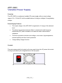
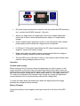
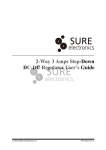
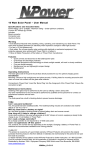
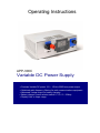
Operating Instructions
APP-300C
Variable DC Power Supply
> Provides Variable DC power 12V ~ 15Volts 350W max power output.
> Optimized radio frequency filtering for radio communications equipment.
> Advanced 3-stage output for battery charging.
> Battery charger current selector switch 0 ~ 10 / 0 ~ 25Amp.
> Display Volts or Amps usage.
APP-300C
Variable Power Supply
Over
Overview
The APP-300C is an advanced variable DC power supply with an output voltage
range of 12v -15Volts DC with the added feature of being an intelligent 3-stage battery
charger.
Power Supply Features.
•
The output voltage of the APP-300C is regulated in 1% range of the selected
level.
•
The design incorporates extensive filters to minimize the radio frequency
interference (RFI) and is suitable to be used with radio communication
equipment.
•
The built-in protection includes over-voltage, over-current, high temperature,
reversed polarity and short circuit protection.
•
3-stage battery charger function
Controls
The mains power switch is located on the rear panel above the AC power inlet socket,
Cooling is provided by the integrated fan on the rear panel.
4 PI4_25C_v_3.0
•
DC power output terminals are located on the front panel the RED terminal is
the + (positive) the BLACK terminal – (Ground)
1
3
4
•
Adjust or 3-stage switch is located below the output variable adjustment
control this is used to select adjustable power supply or 3-stage battery
charger.
•
Output variable output adjustment control is only used while in the variable
power supply function allows the voltage level to be adjusted
•
0~25A and 0~10A switch located below the DC output terminals select the
ampere’s range of the battery charger.
•
Mode switch below the digital readout screen selects either the voltage or
ampere’s reading supplied from the power supply.
•
The two LED’s next to the letter A and V on the readout panel indicate which
readout is being displaying Amps or Volts
Operation
Variable power supply
Before turning on the AC power connect the equipment you wish to power, to the
output terminal’s on the front of the unit check the polarity of the cables, select the
adjust position on the selector switch, please make sure the volts range is turned fully
anti clock wise before turning the AC mains power switch on. The range starts from
12V and can be adjusted to the desired output voltage by rotating the adjustment
control clockwise, turn it anti clock wise to decrees the voltage level.
To check the Amps press the mode button below the digital screen this toggle
between the voltage and Amps reading.
Battery Charging.
Connect the battery to be charged to the output terminal on the front of the APP300C.
4 PI4_25C_v_3.0
Ensure the battery is connected with the RED terminal connected to the battery +
terminal on the and the Black terminal ground connected to the battery – terminal.
Change the selector switch on the front panel to 3-stage this will activate the charger
function, use the selector switch to select the appropriate charging level for the battery
your are charging 0~10A for battery with an ampere hour of 60Ah ~100Ah and 0~25A
for battery over 100Ah.
Further information
When a battery is connected to the APP-300C the display will illuminate and will
remain on until the battery is disconnected, this feature allows the constant monitoring
of the battery charge level when the AC power is off or on indicating when the battery
requires re-charging.
The 0 ~ 10Amp is designed to charge battery’s of 60Ah and above.
The 0 ~ 25Amp is designed to charge battery’s of 100Ah and above.
Battery charging connections should be made from 4.0mm² cables.
The recommended minimum battery capacity is 60Ah failure to follow this
recommendation may lead to permanent damage to your battery
Do not use this unit to charge non-rechargeable batteries.
Batteries should only be charged in well ventilated areas.
Please ensure that the power supply has adequate space and ventilation.
Mounting side rails can be removed and the screw refitted into the case if you wish to
have it free standing or the APP-300C can be mounted using the rails.
4 PI4_25C_v_3.0
APP-300C
Input Voltage
Input Frequency
90 – 264V AC
50 - 60Hz
Output Voltages (adjust):
12 ~15VDC ±1 %
Load Range
Output Power
Standby Current
Protection
0- 10A and 0 – 25A, Selectable Range
375W
2.5mA
Current limit @ 25A ± 1A
Short circuit protection
Overvoltage protection @ 17V ± 1.0V
Thermal protection @ 95oC ±5oC
Output Voltages(3-stage):
Cooling fan operational
Operating Temperature
Storage Temperature
Dimensions
Length:
Width:
Height:
Weight:
Approvals Safety:
Emissions:
Harmonic:
13.8VDC ±1% (BELOW 2A)
14.5VDC ±1% (ABOVE 3A)
Above 6±1A load
-25oC to 50oC
-40oC to 85oC
146mm
181mm
66mm
2.1 Kg
EN60335-2-29, UL60950-1: 2005, 2nd Edition
EN55014, EN55022 Class B; FCC PART 15 B
EN61000-3-2 Class D
4 PI4_25C_v_3.0
Amperor & Associates Ltd.
Unit 5, Kyle Business Park
Cunninghame Road
Irvine, Ayrshire KA12 8JJ
United Kingdom
Telephone No: +44 (0)1294 276096
Fax No: +44 (0)1294 270656
E-mail: [email protected]
www.amperorassociates.co.uk
Manufactured & Distributed by Amperor
Amperor Inc.
11320
Neeshaw Dr.
Houston,
TX 77065, USA
Telephone No: 1-281-807-3320
Fax No: 1-281-807-0886
E-mail: [email protected]
www.amperordirect.com
4 PI4_25C_v_3.0