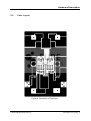
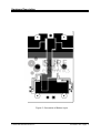
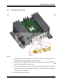
1
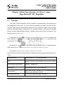
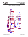
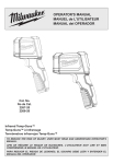
2-Way 3 Amps Step-Down
DC-DC Regulator User’s Guide
© 2004-2008 Sure Electronics Inc.
PT-PC002-Ver1.0
2-WAY 3 AMPS STEP-DOWN
DC-DC REGULATOR
USER’S GUIDE
Table of Contents
Chapter 1.Brief Introduction of 2-Way 3 Amps Step-Down DC-DC Regulator.....1
1-1.
Overview...............................................................................................................1
1-2.
Products Images...................................................................................................2
1-3.
Technical Parameters...........................................................................................3
Chapter2.Hardware Description .....................................................................................4
2-1.
Schematic .............................................................................................................4
2-2.
Parts Layout.........................................................................................................5
2-3.
Phycical .................................................................................................................7
2-4.
Encoder Position Setting for Voltage Adjustment .................................................8
2-5.
How to Connect Load ...........................................................................................9
Chapter3.Test Report .......................................................................................................10
3-1.
Test Instance ......................................................................................................10
Chapter4.Warning .............................................................................................................14
Chapter5.Contact Us ........................................................................................................15
© 2004 -2008 Sure Electronics Inc.
PT-PC002- Ver1.0-page i
2-WAY 3 AMPS STEP-DOWN
DC-DC REGULATOR
USER’S GUIDE
Table of Contents
NOTES:
© 2004-2008 Sure Electronics Inc.
PT-PC002- Ver1.0-page ii
2-WAY 3 AMPS STEP-DOWN
DC-DC REGULATOR
USER’S GUIDE
Chapter 1.Brief Introduction of 2-Way 3 Amps
Step-Down DC-DC Regulator
Overview
1-1.
This 2-way 3 Amps step-down DC-DC regulator is manufactured by Sure Electronics
and designed for heavy duty. It is a low cost, high reliability and heavy duty load DC-DC
converter. Both ways could provide 3A continuous output and work stably. Output voltage
could be switched among 3.3/5/9/12/15V by encode switches, and could be adjusted
through multiturn potentiometers exactly. If needed, other output levels can be got by just
changing some resistor value.
All regulators had been 100% tested in full load condition, and the burn in test time had
been lasted for over 12 hours in several conditions. Test condition is 2-way 2ohm load
connected to 5V output.
All test results were from real measurement, and all diagrams were printed directly from
DSO’ screen capture. We promise that all such snaps are reliable and trusty.
If not mentioned particularly, the test conditions are as follow.
Open environment air flow cooling, without auxiliary fan cooling, and each test would last 12
-hours.
Digital Multimeter
YOKOGAWA 7555 5 1/2 Digit Multimeter
DSO
Tektronix TDS1012 with TDS2CMA Communication Module
Digital Infrared Thermometer
Tempgun Raytek MT4
Data Logger
Self-Designed Product of Sure Electronics
Power Source
Mean Well S-350-27 350Watt, 27V, 13A switching power
adapter, output adjusted to 24V DC
Input Ripple and Noise
37.5mV RMS, 244mVp-p, @24V, 6A output
© 2004-2008 Sure Electronics Inc.
PT-PC002- Ver1.0-page 1
Brief Introduction of 2-Way 3 Amps Step-Down DC-DC Regulator
This DC-DC regulator could work with most linear and switching power adapters with
their voltage output between 9-24V, and current output not less than 5A. This regulator can’t
provide voltage higher than input voltage, and its maximum stable output is equal to input
voltage minus 3 Volts.
1-2.
Products Images
1. Top View
Figure 1
2. Block Diagram
Input
Output
Noise
Filter
Input
Rectifier
Converter
Output
Rectifier
Error AMP
Protection circuit
Figure 2
© 2004-2008 Sure Electronics Inc.
PT-PC002- Ver1.0-page 2
Brief Introduction of 2-Way 3 Amps Step-Down DC-DC Regulator
1-3.
Technical Parameters
DC output range could be selected by encode switch. All regulators have passed full load
burn-in test.
Protections. . . . . . . . . . . . . . . . . . . . . . Short Circuit / Overload/Wrong DC Input Polar
Cooling. . . . . . . . . . . . . . . . . . . . . . . . . Cooling by Radiation and Air Flow
Temperature Increase . . . . . . . . . . . . . 28 Centigrade with Full Load, 12 Centigrade with
50% Load
DC Input Voltage Range . . . . . . . . . . . 5-24Volts DC
DC Inrush Current . . . . . . . . . . . . . . Cold Start, 40A at 24Volts DC, with 15Volts, 3A
Dual Way Output
DC Adjustment Range . . . . . . . . . . . . +10% to -15% Rated Output Voltage (@15Volts
Output)
DC Output Range. . . . . . . . . . . . . . . . . 3.3/5/9/12/15Volts, Adjustable by Encoder
Overload Protection . . . . . . . . . . . . . . . Short Circuit Protection (Not Guaranteed)
Rise. Hold up. Adjust Time . . . . . . . . .10ms. Not less than 2ms. Less than 100 µs at Full
Load and 24V DC Input 100% Threshold
Working Temperature . . . . . . . . . . . . . 0~45℃@100%, -10℃@80%, 55℃@60% Load
Connection . . . . . . . . . . . . . . . . . 2P/7.62mm Pitch Terminal Block for DC Input,
3P/7.62mm Pitch Terminal Block for DC Output.
Packing . . . . . . . . . . . . . . . Net Weight 0.38kg/13.4Ounce; Gross Weight
0.5kg/17.6Ounce
© 2004-2008 Sure Electronics Inc.
PT-PC002- Ver1.0-page 3
CON2
-
+
J1
2
1
1N5819
2
1N5819
2
1N5819
2
1N5819
2
1N5819
2
D1
1
D2
1
D3
1
D4
1
D5
1
+
+
VIN
1
2
1
2
C9
104
C6
220uF/25V
VIN
JP2
104
220uF/25V
1
3
5
7
C2
C1
JP1
1
2
1
2
2
4
6
8
1
1
R14
R9
R11
R12
R13
822
332
562
562
V IN
U2
682
V IN
682
R6
U1
822
332
562
562
R1
R3
R4
R5
SW DIP-4
2
4
6
8
SW DIP-4
4
3
OUTPUT
LM2596
ON/OFF
FB
GND
3
4
FB
GND
OUTPUT
LM2596
5
ON/OFF
5
2
R15
2
R7
562
562
1
R10
1
R2
2
3
3
1N5819
D9
10K
1N5819
D6
10K
2
1
2
2
1
2
1
2
1
1N5819
D10
R16
1N5819
D7
R8
2
1
2
1
L1
L3
1N5819
D11
103
1N5819
D8
103
33uH
33uH
1
2
1
2
+
+
220uF/25V
C7
L4
220uF/25V
C3
L2
33uH
33uH
1
2
1
2
+
+
104
220uF/25V
C10
104
C8
220uF/25V
VOUTB
C5
C4
VOUTA
1
2
© 2004-2008 Sure Electronics Inc.
1
3
2
1
CON3
3
2
1
J2
2-1.
2
1
3
5
7
2-WAY 3 AMPS STEP-DOWN
DC-DC REGULATOR
USER’S GUIDE
Chapter2.Hardware Description
Schematic
Figure 3
PT-PC002- Ver1.0-page 4
Hardware Description
2-2.
Parts Layout
Figure 4 Connection of Top Layer
© 2004-2008 Sure Electronics Inc.
PT-PC002- Ver1.0-page 5
Hardware Description
Figure 5 Connection of Bottom Layer
© 2004-2008 Sure Electronics Inc.
PT-PC002- Ver1.0-page 6
Hardware Description
2-3.
Phycical
Figure 6
© 2004-2008 Sure Electronics Inc.
PT-PC002- Ver1.0-page 7
Hardware Description
2-4.
Encoder Position Setting for Voltage Adjustment
Output
Voltage
Encoder Position Setting①②③
3.3V
JP1/JP2
5V
JP1/JP2
9V
JP1/JP2
12V
Set JP1,JP2 to adjust voltage
JP1/JP2
15V
JP1/JP2
①
Input Voltage must be 3V higher than output voltage. For example, if you need a 9V
output, the input voltage must be not less than 12 volts.
②
Input Voltage can never be AC source. Ripple and Noise should be less than 1Vp-p.
Input power should be at least as 1.5 times as output power.
③
All power cable should be AWG14 or those which have larger diameter.
© 2004-2008 Sure Electronics Inc.
PT-PC002- Ver1.0-page 8
Hardware Description
2-5.
How to Connect Load
D
GN
T1
OU
T2
OU
Load
Load
Figure 7
Notice:
1.
Negative (Minus) output should be connected to GND or the housing of your
instrument, which is also GND of the whole board.
2.
Additional fan is suggested. With fan the temperature increasing could be as
low as 10 centigrade when 100% load.
3.
If this DC-DC adapter is used in sealed environment and work at fully output,
the temperature increasing would be dangerous. Never place any flammable
material near the converter.
4.
Never connect inductive load.
© 2004-2008 Sure Electronics Inc.
PT-PC002- Ver1.0-page 9
2-WAY 3 AMPS STEP-DOWN
DC-DC REGULATOR
USER’S GUIDE
Chapter3.Test Report
3-1.
Test Instance
Item and
Test
condition
3.3V,1A
3.3V,3A
5V,1A
5V,3A
9V,1A
9V,3A
12V,1A
12V,3A
15V,1A
15V,3A
(1)
Output
Tol.
(1)
Noise
P-P
RMS
Efficiency
OUT1
OUT2
OUT1
OUT2
OUT1
OUT2
OUT1
OUT2
OUT1
OUT2
OUT1
OUT2
OUT1
OUT2
OUT1
OUT2
OUT1
OUT2
OUT1
OUT2
Tol. = (V1-V2)/V1
V1--- output voltage without load
V2--- output voltage with load
© 2004-2008 Sure Electronics Inc.
PT-PC002- Ver1.0-page 10
Test Report
SCREEN CAPTURE FROM DSO
RIPPLE OF 5V 1A OUTPUT, RMS AND P-P
Figure 8
© 2004-2008 Sure Electronics Inc.
PT-PC002- Ver1.0-page 11
Test Report
RIPPLE OF 12V 1A OUTPUT, RMS AND P-P
Figure 9
OSCILLOGRAM OF OUTPUT WAY1 IS SHOWN IN CHANNEL 1 OF THE DSO.
OSCILLOGRAM OF OUTPUT WAY2 IS SHOWN IN CHANNEL 2 OF THE DSO
© 2004-2008 Sure Electronics Inc.
PT-PC002- Ver1.0-page 12
Test Report
Long
Output Power
100
Endurance
80
-10℃ 0℃
45℃
Short
Max Output Power
3-2.
70℃
Environment Temperature
Low
Environment Temperature
High
Figure 10
© 2004-2008 Sure Electronics Inc.
PT-PC002- Ver1.0-page 13
2-WAY 3 AMPS STEP-DOWN
DC-DC REGULATOR
USER’S GUIDE
Chapter4.Warning
1.
Please check the voltage and polarity of the input power. Make sure that the input
voltage is lower than DC 24V and higher than 5V, and constant output current is not
less than 5A, otherwise the output may not be stable enough.
2.
Make sure that the output is not short, or it will burn the input adapter and the converter
immediately. Protection built in short circuit could not act unless current is high enough
but such current may damage the adapter.
3.
Make sure that the metal screws do not short any circuit.
4.
If users want to measure the RMS current, it is suggested that use a shunt resistor in
the circuit and test the voltage drop. Be careful of the too high peak current.
5.
Normally the GND of the converter should be connected to the Protection Earth (PE)
terminally. Leave it float if you can’t make sure how to connect the Protection GND.
Use AWG14 or higher diameter cables in the circuit.
© 2004-2008 Sure Electronics Inc.
PT-PC002- Ver1.0-page 14
2-WAY 3 AMPS STEP-DOWN
DC-DC REGULATOR
USER’S GUIDE
Chapter5.Contact Us
Sure Electronics Co., Ltd.
Floor 5, A zone,
Qinhuai Technology Innovation center,
NO.105-2, DaMing Road,
Nanjing,
China
Tel:
+86-25-66606340
(English service, from GMT1-10AM, only for technical questions)
Email:
[email protected]
Website:
www.sure-electronics.net
© 2004-2008 Sure Electronics Inc.
PT-PC002- Ver1.0-page 15