1
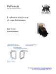
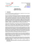
HAWKER ELECTRONICS LTD
OPERATING AND INSTALLATION
INSTRUCTIONS FOR THE PM1
IMPORTANT
This unit has been tested to the standards listed on its certificate of conformity. It is
the responsibility of the installer / user to ensure the system and installation conforms
to any relevant standards.
Loss of safety features could occur if used outside the specified parameters or
incorrectly installed.
Installation and commissioning of this unit should be carried out by a suitably
competent person. This document should be read in conjunction with other product
literature for best performance.
All fault finding especially when a voltage loss or failure is suspected or indicated by
the unit should be done with the supplies isolated and by a competent body.
The unit contains no user serviceable parts.
Brief Description
The PM1 monitors up to three ac inputs and converts them to proportional dc mA
currents respectively. Volt free contacts are available to indicate loss of the input
voltages.
Detailed Operation
A signal in the range of 0 to 300Vac is input to each channel, a proportional current
output in the range of 4 to 20mA is produced. This current can be used for
monitoring purposes and will drive into several hundred ohms. The circuit draws its
power from the input signal being monitored thus no auxiliary power supply is
needed. Obviously 4mA will never be a valid level and the lowest current level will
be approximately 6mA. Light duty volt free changeover contacts are available to
signal abnormally low, or loss of, voltage this level is factory set. A fixed hysteresis
is incorporated to stop relay chatter during fluctuation of the low- level input signal.
Three separate channels are available on the unit these need not all be used if not
required. The input signals may be from different sources or the user can link the
neutral connections to monitor three lines of a three-phase supply.
PM1InstA.doc
1
The output current loops are isolated from each other and earth, and the ac input via
the input transformers.The output current is driven from an internally derived nominal
12Vdc supply.
Mounting and Installation
The unit is mounted as shown below in a permanent position usually inside a panel on
Din rail, the unit is supplied with two 35mm Din mounting brackets.
The unit uses a plug and socket arrangement for connection of incoming and outgoing
signals, this allows for easy connection / disconnection without the need to open the
enclosure. These plugs are not designed for frequent connection and disconnection.
The ac-input voltage to each used channel should be supplied via a local isolating
fuse. The fuse rating must not exceed 100mA, an anti-surge type is recommended.
The output current and relay signals although low voltage should have an adequate
means of protection and isolation determined by the user / installer.
in CH1
in CH2
in CH3
Hawker
Electronics
Ltd.
+44 (0)121 453 8911
PHASE MONITOR
Type PM1
Channel 2
Channel 1
Rly mA
CH1
Rly
mA
CH2
Channel 3
The ac inputs are via 3-pin plugs which
connect to 3-pin sockets mounted externally
on the enclosure top. The volt free contacts
and current loop exit from the bottom, for
each channel respectively. The relay contacts
and current connections are via 4-pin plug
and sockets. The user terminates incoming
wiring to the plugs only, the sockets are
factory pre-wired.
Rly mA
CH3
If a three-phase supply is being monitored the common “N” neutral of the three
phases may go into any “N” and be linked on the plugs. In this configuration care
must be taken, as 415V may be present inside the unit.
The volt free contacts and current are terminated as below. Careful positioning and
segregation should be used to avoid noise problems. The Led for each channel can be
seen below the channel identification boxes.
PM1InstA.doc
2
Plug connections
4-20mA Current output (4-Pin)
1
not connected
2
not connected
3
I+
4
I-
Inside view of 4-pin plug
1
E
4
Relay Volt free contacts (4-Pin)
1
not connected
2
Common
3
Normally Closed
4
Normally Open
3
2
Inside view of 3 pin plug
Voltage a/c Input (3-Pin)
E
L
N
Earth
Live
Neutral
E
N
L
IMPORTANT THIS EQUIPMENT MUST BE EARTHED
ENSURE THE CORD GRIP IS USED ON ALL
FITTED PLUGS.
General
It is important never to exceed the channel maximum input volts, this is 300V
between any channels Live and Neutral terminal. Even so using the neutral as the
common reference it is possible to monitor a three-phase supply.
Rectangular boxes are outlined on the lid label showing the Red, Yellow and Blue
channels when monitoring a three-phase supply. These can be ignored and may not
be relevant when monitoring single phases of different supplies or when different
installation colour coded conductors are used. The user must ensure correct phase
connections and identification.
Indication of a low/loss of volts
If a loss of volts occurs or the input voltage level drops below the pre-set valve the
corresponding channel led will extinguish and the user relay will de-energise. When
fault finding it must be remembered to take extreme care and to use approved tools or
equipment to diagnose the problem. All voltages must be isolated for safety when
work is carried out, in case the supply corrects itself. This equipment is for mains
fluctuation monitoring purposes it is not intended to be used as a voltage meter.
PM1InstA.doc
3
Technical Specifications
Taken @ 25°C
Input
40 to 300Vac 50Hz per channel *
30mA max per channel
Min I/P.
Volts
Approx. 40Vac
Output
Current
350 Ohms max
min. 6.1mA @ 40Vac I/P
max 20mA @ 300Vac I/P
User Relay
For volts failure detection
S.P.C.O. Normally energised Volt Free Contacts
max switching 1A @ 30Vdc
Relay
Drop out volts
Approx. 50Vac Input (Factory Set)
User Relay pull
In volts
Greater than approx. 60Vac Input
Led
Green, illuminated when User relay energised.
Accuracy
Linearity
Op temp
better than 3%
2%
-10°C to +40°C
Enclosure
Polycarbonate, Low Halogen, LxWxH 240 x 160 x 90
IP50 with Plug and Sockets terminations.
Fixing
Standard 35mm Din Rail
Weight
1.6Kg
* The nominal input voltage is 240Vac however the unit will monitor up to an
absolute maximum 300Vac. A maximum continuous time of 4 hours at 300V at
+40°C should not be exceeded, the unit should then be returned to the nominal
voltage or less for an equal time period.
B eca use o f co n tin uin g d evelo p m en t w e reserve th e rig h t to ch a ng e th e sp ecifica tio n s w ith o ut n o tice.
Fo r a fu ll list o f H A W K ER p ro d u cts a n d a p p lica tio n n o tes visit o u r w eb site a t w w w .h a w ker-electro n ics.co .u k
H A W K ER ELEC TR O N IC S LTD .
5 7 Th e A ven u e,
Ru b ery In d u stria l Esta te,
B irm in g h a m B 4 5 9 A L, EN G LA N D
Telep h o n e :+ 4 4 (0 )1 2 1 -4 5 3 -8 9 1 1 Fa x : + 4 4 (0 )1 2 1 -4 5 3 -3 7 7 7
e.m a il: in fo @ h a w ker-electro n ics.co .u k
PM1InstA.doc
O&M 63
Issue A
Sept 02
FM 10000
4
According to the
EMC Directive 89/336EE and Low-Voltage Directive, 73/23/EEC
Including amendments by the CE Marking Directive, 93/68/EEC
Type of equipment:
Brand name:
Type model:
Manufacturer:
Manufacturers Address:
Vac to mA Signal Converter
Phase Monitor
PM1
Hawker Electronics Ltd.
51 The Avenue, Rubery Industrial Estate, Rubery,
Birmingham, B45 9AL. U.K
Tested to the following harmonised European EMC standards: Generic Standards EN50081/2 Using EN55011 Class A limits
EN55011 Class A Conducted Emissions,
EN55011 Class A Radiated Emissions,
EN61000-4-4 Fast Transient Bursts,
EN61000-4-2 Static Discharge,
PASS
PASS
PASS
PASS
Tested to the following harmonised European Electrical Safety Standards: BS EN 61010-1 :2001
Safety requirements for electrical equipment for
measurement, control and laboratory use.
Additional information
Indicate below compliance, with reference to the above Directives:
X
The product complies with the harmonised European safety standards listed above.
The product complies with good engineering practice in safety matters within the EEA, including
parts of the safety standards / specifications listed above.
X
We have an internal production control system that ensures compliance between the manufactured
products and the technical documentation.
As manufacturer / the manufacturer’s authorised representative established within the EEA, we declare under our
sole responsibility that the equipment follows the provisions/Directives stated above.
Signed …………………… Date…………
M Armstrong
Technical Director
PM1InstA.doc
5