1
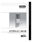
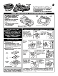
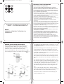
AR1535 Ed A.qxd
27/10/08
10:13
Page 1
IMPORTANT SAFETY INFORMATION
Installation and operating Instructions for:
100mm – 4 inch Slimline Extractor Fan
Models:
GFANC4SL, GFANC4SLT, GFANC4SLC &
GFANC4SLTC
GENERAL INSTALLATION INSTRUCTIONS
Select a suitable location and make a hole in the wall (or
ceiling) approximately 100mm (4”) in diameter, allowing
sufficient clearance for the ducting. Ensure that there is no
obstruction on the outside wall or above the ceiling.
Note: For wall installations a fall is recommended i.e. a slight
slope running from the fan to the outside wall, see diagram 1a.
Please read before starting installation
This unit should be installed and maintained by a competent
person (i.e. a qualified electrician) in accordance with these
instructions and in accordance with the current edition of the IEE
Wiring Regulations (BS7671) and appropriate statutory regulations.
It is essential that the power source is disconnected and isolated,
prior to installation and maintenance.
The fan must be connected to a double pole, fused, switched
connection unit (FCU) having a contact separation of at least 3mm
in all poles and fitted with a 3amp fuse. This must be sited outside
a room containing a fixed bath or shower.
Some types of fluorescent/low energy lighting systems can
interfere with the timer operation. To ensure reliable operation only
connect fans to tungsten filament lighting circuits.
These fans are double insulated and do not require an earth
connection.
The location of the fan is important, both for its safe operation and
for the efficient extraction and replacement of air within a room.
For best results the fan should be mounted as high and as far away
as possible from the main source of air replacement in a room
(i.e. opposite the internal door way).
If the fan is sited in a room containing a fuel-burning appliance, the
installer must ensure that the air replacement is adequate for both
the fan and the fuel-burning appliance.
These fans are not suitable for installation within a shower cubicle
or directly above a fixed bath.
The IEE wiring regulations require that mains voltage fans, in a
room containing a bath or shower, must be positioned out of the
reach of a person using the bath or shower and that the fans are
located well away from all sources of water spray.
This fan is not intended for use by children or other persons
without supervision if their physical, sensory or mental capabilities
prevent them from using it safely. Children should be supervised to
ensure that they do not play with the fan.
For installations extracting through cool air spaces, i.e. a loft,
a condensation trap must be formed by bending the ducting,
see diagram 1b and 1c.
Remove the small plug from the bottom edge of the front
cover and undo the small screw, retaining the front cover.
Unclip the front cover and remove. Hold the body of the fan
to the wall or ceiling and mark and drill the fixing holes and
appropriate cable entry point.
Connect the flexible ducting to the fan and secure the end
with a cable tie. Place the other end of the ducting into the
hole in the wall and feed it in as the fan is offered up to the
wall.
Use wall plugs and screws to fix the body of the fan to the
wall. From the outside, pull the ducting through the hole and
out the other side by about 75mm (3”). Connect the ducting
to the wall grille, securing it with a cable tie. Feed the
ducting back into the hole as the grille is offered up to the
wall. Use wall plugs and screws to fix the wall grille to the
wall.
Prior to connecting the extractor fan to the mains supply,
check that the body of the fan has not become distorted and
that the fan blade can rotate freely within its housing.
Connect the cable to the fan and the electrical supply as
shown in diagram 2a or 2b.
AR1535 Ed A.qxd
27/10/08
10:13
Page 2
Timer Adjustment
For models fitted with a timer, adjust to the required overrun
period by turning the control with a small screwdriver. A hole in
the PCB cover is provided to guide the screwdriver. Turn the
control clockwise to increase the time and anti-clockwise to
decrease it. The approximate time variation is 3 to 25 minutes
NOTE: The timer control is a precision component. DO NOT
apply excessive force when making adjustments.
Terminal 1 -
Switched Live Supply
Refit the front cover and retain by tighten the small screw.
DO NOT OVER TIGHTEN. Replace the small plug to cover
the screw.
Terminal 2 -
Neutral Supply
Terminal 3 -
Permanently Live Supply
IMPORTANT NOTICE – TIMER VARIANTS
Please note the following points when installing and operating
timer controlled fan variants.
It is quite normal for the front cover of the timer-controlled
fans to feel slightly warm to the touch. This is the result of the
correct operation of the electronic circuit and is not a cause
for concern.
Terminal 1 -
Spare
Terminal 2 -
Neutral Supply
Terminal 3 -
Live Supply
CLEANING AND MAINTENANCE
IMPORTANT NOTICE: Wiring Colour Changes
Regular cleaning of the fan is recommended. Before cleaning
isolate the fan completely from the mains supply.
As from 1st April 2004 new installations in the UK, could be
wired using the new EU Harmonised colours for the supply
conductors of twin and earth cable:
If required the front cover can be removed and, using a soft
dry brush, remove excess dust and wipe the plastic parts with
a damp cloth.
Do not immerse the fan in water or other liquid.
Never use strong solvents to clean the fan.
For fans with decorative, plated front covers, use only a clean,
dry, soft cloth and polish the cover gently.
Do not use strong solvents or other cleaning agents as this
could damage the plated surface.
New colours
Old colours
BROWN - Live
RED - Live
BLUE - Neutral
BLACK - Neutral
The old colours will cease to be used from 1st April 2006
Flexible cable colours remain unchanged
BROWN – LIVE
BLUE – NEUTRAL
Specification – All Models
Supply Voltage
230V – 50Hz
Power
20W maximum
Extract Capacity
93m3 per hour
IP Rating
IPX4
Max Ambient Temperature
400C
Double insulated
Complies with BSEN 60335-2-80: 2003
GET plc, Key Point, 3-17 High Street, Potters Bar,
Hertfordshire, EN6 5AJ England
Helpline Telephone 0121 565 7770
www.getplc.com
AR1535 Ed A