1
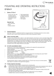
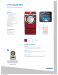
MOUNTING AND OPERATING INSTRUCTIONS
CF 51/55
1.
Delivery CF 51/55
- 1 calculator with battery (optionally with mains power supply)
- 1 wall mounting bracket
- package with material for sealing, screws, wall plugs
- mounting and operating instructions
Required tools:
3 mm screwdriver
Crosstip screwdriver
2.
General indications
Calculator CF 51/55 is a sophisticated electronic measuring instrument.
The following instructions must be carefully observed in order to ensure
correct mounting and to fulfill all safety and guarantee conditions.
2.1
Advice concerning safety
Hot water circuits and mains power supplies run under high
temperatures and pressures as well as under high voltages. When operated incorrectly, these may cause serious injuries. Due
to this, the measuring units may only be installed by qualified and trained personnel. If the calculator casing is submitted to
strong shocks, impacts, drops from more than 60 cm height or similar stresses, the calculator must be replaced. Before
opening the meter, mains voltage (optional) must be isolated.
2.2 CE marks and protective classes
Metering unit CF 51/55 fulfills all requirements of EC guidelines and is approved for environmental class C
(industrial applications) according to DIN EN 1434:
•
•
•
•
•
•
•
ambient temperature:
+5 °C … +55 °C (indoors installation)
storage temperature (without battery): -10 °C … +60 °C
relative atmospheric humidity:
< 95 %
absolute altitude:
< 2.000 m
protective class IP 64 according to DIN EN 60529 (protection against dust and splashing)
EMC protection according to DIN EN 50081-1/2, DIN EN 50082-1/2
double protective insulation
(protective class II according to IEC 60364-4-443)
•
Discarded electronic devices or batteries contained within the calculator must not be disposed with
domestic waste. Dispose in accordance to local regulations.
2.3 Further important instructions
•
Mounting position shall be selected so that the connecting cable of the flow meter and the temperature probe cables will
not lie near mains cables or other sources of electromagnetic disturbances (minimum distance 50 cm.).
• Cables must not be installed along pipes reaching temperatures above 55 °C.
• Opening of calibration seals will cause the loss of calibration validation and of guarantee.
• The casing may only be cleaned on the outside with a soft, damp cloth. Do not use detergents.
• Installation must be carried out according to DIN 4713 or DIN EN 1434.
• Some special functions (e.g. when using the tariff and data logger function with CF 55) requires parameters setting
of the calculator through M Bus or optical interface.
1
3.
Mounting the calculator
3.1
Mounting instructions
•
•
•
Never carry out welding or drilling work near the meter.
Leave the meter in its original package until all connections, insulating, painting and cleaning tasks have been performed.
Pulse weight and mounting position (supply and return) of the flow meter must agree with data printed on the
nameplate of the CF 51/55.
The calculator must be protected against damages caused by shocks or vibrations which may occur at the mounting site.
Type and basic value of the temperature probes to be connected must agree with the data indicated on the nameplate.
The calculator may be installed optionally on the wall, on a cool pipe or directly on the flow meter when type US Echo II
flow meters are being used.
•
•
•
3.2 Mounting on the wall
If temperatures in the heating circuit are permanently higher than 90 °C, or if ambient temperature is more than 55 °C, it is
recommended to mount the calculator on the wall. Screw the supplied wall support to the wall or fasten it to a cool pipe.
35,2 mm
Set the calculator with an
angle of 45° on the support
35 mm
Rotate calculator 45° until it
engages.
69 mm
3.3 Mounting on flow meter US Echo II
The calculator should not be mounted on the flow meter when ambient temperature is permanently higher than 55 °C or
when cooling operation is being performed.
Rotate 45°
Rotate
45°
Set the calculator with an
angle of 45° on the support
Rotate the calculator 45° till
it engages.
2
4
Connecting temperature probes and flow meter
4.1
Preparation
• Loosen lateral casing screws and remove upper part of casing.
• Introduce all connecting cables into the lower casing part
through the cable glands.
• Location of the cable depends on the diameter
of the cables and taking into account the utilization of option
boards and mains power supply and according to the following
recommendations:
Cable glands
1. 쏗 4.25 ± 0.75 mm2 – T. probe (supply)
2. 쏗 4.25 ± 0.75 mm2 – T. probe (return)
3. 쏗 6 ± 1 mm2 – mains power supply – optional
4. 쏗 4.25 ± 0.75 mm2 – optional
5. 쏗 4.25 ± 0.75 mm2 – optional
6. 쏗 6 ± 1 mm2 – T. probe (supply)/optional
7. 쏗 6 ± 1 mm2 – T. probe (return)/optional
8. 쏗 3.75 ± 0.75 mm2 – flow meter
3
1
2
4
5
6
7
8
4.2 Temperature probe
Only use pairs of temperature probes with the same serial number. Probe cables must not be shortened or lengthened. Probes must
be mounted according to the guidelines EN 1434.
Connecting specification:
• Connection
• Cable diameter
• Maximum wire section
• Type
2 wire technology, for CF 55 also 4 wire technology
3.5 mm … 6,5 mm
0.2 … 1.5 mm2
PT100 or PT500 according to DIN EN 60751
Observe nominal value of calculator – cf. nameplate.
4.2.1 Connecting of temperature probes
The following figures (4.2.2 and 4.2.3) and descriptions cover the connection of temperature probes in heating circuits. When
connecting temperature probes in cooling circuits or in combined heat-cooling circuits, please observe the following connecting
instructions:
Warm connector
Cold connector
Heating-heat flow circuit
Cooling circuit
Combined heating-cooling circuit
supply probe
return probe
heating supply probe
return probe
supply probe
heating return probe
• Pierce cable glands 1 and 2 of the calculator
• Pull the supply temperature probe cable (= warmer line)
through cable gland 1 and the return probe
cable (= colder line) through cable gland 2 .
• Make a loop to resist tension and loop over
the corresponding support (cf. figure).
• Connect wires according to the plan of terminal connections.
3
4.2.2 Plan of terminal connections for CF 51
Supply
Return
Fig.: probe connection with 2 wire technology
4.2.3 Plan of terminal connections for CF 55 (connection with to 4 or 2 wire technology)
Supply
yellow
green
blue
white
yellow
green
blue
white
Warning: when connecting temperature probes with 2 wire technology to a CF 55 metering unit, the connecting terminals must be
bridged, as shown in the figure.
Return
Supply
Fig.: probe connection with 4 wire technology
Return
Fig.: probe connection with 2 wire technology
4.3 Flow meter
Conventional flow meters with 2 wire connection or US Echo II flow meters with 4 wire connection may be connected to the
calculator.
Using US Echo II flow meters allows for the transmission of trouble warning messages to the calculator over a data cable and for
power supply of the ultrasound flow meter through the calculator, in addition to transmission of pulses.
Pulse input specification
Pulse input:
Pulse generator:
Pulse weight:
Max. pulse frequency CF 51
Max. pulse frequency CF 55
Resistors Ron / Roff
Cable diameter
Section of wire
4
characteristic according to EN 1434-2 Class B
reed contact, open collector, open drain or static relay
observe nominal value of calculator (cf. nameplate)
16 Hz
128 Hz
≤150액 / 욷2 M액
3.75 ± 0.75 mm
0.2 … 1.5 mm2
4.3.1 Connecting type US Echo II flow meter
• Pierce cable gland 8 of the calculator (cf. Figure in 4.1)
• Make a loop to resist tension and loop over the corresponding support
• Connect wires according to the color code (red wire last)
+
-
P
D
+
-
P
D
Earth
(black)
+
Voltage
(red)
P
Impulse
(blue)
D
Data
(white)
Remark: different versions of US Echo II with supplementary PulsBox are connected box are connected to the calculator as described
under Point 4.3.2. Please find details in the documents concerning US Echo II.
4.3.2 Connecting of conventional flow meter
•
•
•
•
•
Pierce cable glands 8 of the calculator (cf. Figure in 4.1).
Make a loop to resist tension and loop over the corresponding support.
When connecting pulse generators based on reed contacts (standard for volume measuring devices with mechanical metering
units), polarity must not be observed.
When connecting electronic pulse generators (e.g. Open Collector), please observe polarity!
Connect the diverse wires according to the terminal connection plan.
+
+
-
-
P
P
D
D
P
Impulse
Earth
4.3.3 Connecting type US-Echo DN 65 and DN 80 flow meter
• Pierce cable glands 8 of the calculator (cf. Figure in 4.1).
• Make a loop to resist tension and loop over the corresponding support.
• Connect wires according to the color code.
+
Earth
(blue)
-
P
D
P
Impulse
(yellow)
5
5.
Power supply for calculator
Two types of power supply are available. As a standard, a 6 years battery is supplied.
5.1
6 years battery*
Type 2 x lithium 3.6 V-AA soldered to an insert board
•
•
•
•
•
Lithium
3,6 V-AA
Only use original battery
Do not recharge, open, heat to more than 100 °C, expose
to open flame or immerse in water.
Do not dispose through domestic waste. Dispose according to local
regulations
Connect battery using plug-in connectors.
Place battery into the corresponding recess
In the calculator casing and engage.
CAUTION: when battery has been disconnected for more than one minute,
it may be necessary to reset the interior clock.
* Optional: 12 years battery on request.
5.2 Mains option
Mains voltage
Mains frequency
Maximum power requirement
Type of cable
Cable diameter
Wire section
230 V ± 15 %
50 Hz ± 2 %
1 VA
2 wires (no earth)
4.5 mm … 7.0 mm
0,5 mm2 … 2.5 mm2
27 28
•
•
•
•
•
•
Mains
option
•
Heat meters with mains power supply must be connected
according to installation regulations. Power supply must be
protected against voltage failures. Protective systems
(circuit breakers) must be used in order to ensure
safe separation of the unit from the mains power supply if
electrical problems should occur (breaking current < 1 A).
An emergency circuit breaker should fulfill the following requirements:
• be installed within reaching distance
• be clearly recognizable as an emergency breaker
• separate both wires
• clearly indicate on/off position
The connecting cable of the mains option must be directly connected to the breaker switch
Switch off mains power (cut off switch)
Open casing of calculator and connect the mains power supply to the meter by means of the plug.
Introduce the mains option board into the corresponding recess in the casing.
Pierce the third cable gland from the right and pull through the mains power supply cable.
Clamp the cable using the tension relieving system.
Connect wires to terminals No. 27 and 28 (safe guard against wrong
polarity, strip cable insulation 8 mm)
Close casing lid and switch on mains power.
6.
Startup
•
Check all functions, especially the correct display of
temperatures and volume stream.
Replace upper part of casing and screw together.
Secure screws with users seals (supplied plastic seals or wire seals).
•
•
•
•
•
•
•
•
6
7.
Operating instructions CF 51/55
A heat meter is a measuring instrument used to record energy released in a heating or cooling system. The partial compo
nents consist of a pair of temperature probes, a flow meter and a calculator, each component being subject to compulsory
calibration for commercial utilization. The metering unit records the measurement values of the pair of probes and of the flow
meter, permitting the display of data over 3 separate display levels.
Display level 1: billing level (cumulated energy and volume display)
Display level 2: service level (actual operating data of the heat meter)
Display level 3: due day level (13 monthly values of cumulated energy and volume)
7.1
LC display and signification of the segments
1
2
3
4
5
6
14
7
13
12
11
10
9
8
1. Alarm symbol: energy measurement stopped. See 7.3.6
2. “Dirty transducer warning”: energy measurement continued, cleaning of the flow sensor is necessary
3. Temperatures: appears for temperature related displays or for displays of cooling energy in case of combined
heating/cooling meters.
4. Flow display: permanent symbol: flow is present / flashing symbol: no flow
5. Date & time: representation of date and time indications related to time dependent displays, e.g. due day values and maximum
values.
6. Display level: actually selected display level
7. Unit: physical unit
8. Decimal point
9. Pulse weight display: concerns the pulse weight of the metering unit (only CF 51 and CF 55) or pulse weight of exterior connec
ted water meters (only when a corresponding option board is being used)
10. Maximum value: appears when maximum values are displayed
11. Operating time: appears for operating time display
12. Threshold values (only for CF 55): display concerns threshold value/tariff function (1 or 2)
13. Water meter 1 or 2: display concerns exterior water meter (1 or 2)
14. Main display area: 7 digits for the display of all values displaying all cumulated and actual values
7
7.2
All display levels and displays in detail
Depending on the type of unit, the actual range of display may differ from the one shown here. Pressing of the push button activates
the LC display. Switching of levels is achieved by prolonged pressing for 2 sec. of push button
, change of display through short
pressing of push button
.
Flow
Failure hours
Power
Error code temperatur measurement
Volume
Supply temperature
Error code flow measurement
LCD-Test
Return temperature
Energy (MWh, kWh of GJ)
Cooling energy (MWh, GJ or kWh)-optional
Overload times
Water meter 1 (optional)
Temperature difference
Mains voltage failure time
Water meter 2 (optional)
Operating time
Integrator time and date (optional)
Threshold value 1 (only CF 55)
Maximum power display
day + month/year/time permanent change of display
M Bus primary address
Energy above threshold value 1 (only CF 55)
Maximal flow value
day + month /year/ time permanent change of display
M Bus secondary address
digits 1-4
Volume above threshold value 1 (only CF 55)
M Bus secondary address
digits 5-8
Threshold value 2 (only CF 55)
Maximal supply temperature
day + month /year/ timepermanent change of display
M Bus baudrate (optional)
Energy above threshold value 2 (only CF 55)
8
Volume above threshold value 2 (only CF 55)
Pulse weight thermal meter
Pulse weight water meter 1/2 (optional)
Due day values energy, month 1 … 13
Due day values cooling energy, month 1 … 13 (optional)
Due day values volume, month 1 … 13
Due day values water meter 1/2 month 1 … 13
(optional)
Software Version
7.3
Indications concerning special display functions (partly optional, depending on type of unit)
7.3.1
Energy and volume index (display levels 1 and 3)
The energy unit is programmed at the factory. As a standard, energy is displayed in MWh, optionally KWh or GJ are possible.
7.3.2 Cooling energy (display level 1)
Display of cumulated cooling energy for energy versions for utilization as combined heating/cooling circuits (please refer to point 10
for more detailed information).
7.3.3 Water meters 1 and 2 (display level 1)
Display of the meter status of connected supplementary water meters with impulse output, using a corresponding option board.
7.3.4 Threshold value display (display level 1 – only CF 55)
Representation of threshold value, energy share, volume and duration in 2 threshold value registers independent from each other
(tariff register). The selection of the threshold value parameters, programming of the threshold values and data reset are performed
over the M Bus or the optical interface. As soon as the energy or volume value is higher than the selected threshold value, energy
and volume shares are recorded in the threshold value registers. The total volume which flowed through the meter during the time
the threshold value was exceeded, is summed up in the volume threshold value register. Time of excess is recorded in the same way
in the time threshold value register.
9
Function of the energy threshold value register as a function of the selected threshold value:
Flow (Q > Qth)
Power (P > Pth)
Temperature difference (dT > dTs)
Return temperature (Tr > Trth)
Supply temperature (Ts > Tsth
7.3.5 Maximum value display (display level 2)
The actual monthly maximum values for power output, flow and supply temperature are displayed with the corresponding time stamp.
Internally, 13 monthly maximum values are stored for each case, which may be read out over the M Bus or the optical interface. The
duration of period to assess the maximum values is 60 minutes. The duration of period may be varied over the M Bus or the optical
interface within a range of 1 min – 1440 min (= 1 day).
7.3.6 Operating trouble alarm (display level 2)
In case of operating trouble, CF 51/55 displays a symbol
. When this trouble alarm appears, maintenance should be called. CF
51/55 shows detailed information concerning operating troubles in special display levels (cf. description of display).
Display level
operation shut down code
A0 = trouble with temperature recording
1 = supply temperature probe is not connected, connection cable is interrupted
or broken
2 = return temperature probe is not connected, connection cable is interrupted
or broken
3 = negative temperature difference; temperature probes were exchanged
(except in case of combined heating/cooling metering)
4 = Analog to digital converter is broken (instrument must be replaced)
Display level
operation shut down code
A1 = trouble with flow measurement
1 = backflow in meter or in pipe system
2 = air in the pipe system, broken ultrasound probe or very strong deposits on the
probes (cleaning or inspection required)
3 = exceeding the maximum admissible flow
* this message is a warning and does not cause measurement shut down.
4 = connection cable with flow transponder or connection to the ultrasound probes
has been interrupted.
5 = no flow for > 24 hours, but DT > 15 K
6 = no data communication between calculator and flow meter
(= normal case for 2 wire pulse generators)
7 = problem with the optional board
10
7.3.7
M Bus parameters (display level 2)
Representation of characteristic data for remote data readout over M Bus or optical interface.
7.3.8 Due day values (display level 3)
Representation of 13 end of the month values of the cumulated values for energy, volume, cooling energy (optional) and volume of
the connected water meters, with time stamp and beginning with the value of the previous month.
8.
Integrated data logger (only CF 55)
Calculator CF 55 is fitted with an integrated data logger for the field analysis of operating parameters in the cooling and heating
systems with the following scope of functions:
•
•
•
•
•
Logger frequency: programmable from 1 minute to 7 days.
Amount of memory: 1008 memory locations per value.
Data: 6 selectable registers (cumulated and instantaneous values).
Supplementary recording of the fault status.
Programming and reading of the data logger over M Bus or optical interface.
9.
Insert optional boards
The function range of the calculator may be extended for data communication and data remote display by means of different option
boards. The following option boards are available:
•
•
•
•
•
•
M Bus + 2 exterior water meters
M Bus and energy + volume remote display
LON + 2 exterior water meters
Modem + 2 exterior water meters
Double M Bus (only CF 55)
RF + 2 exterior water meters
Details concerning mounting and start up are described in the mounting and operating instructions of the corresponding option
boards.
10.
Special version for use in cooling and combined heating/cooling circuits
10.1
Calculator for utilization in cooling circuits
For these product versions, the calculator has been identified and programmed at the factory especially for utilization in
cooling systems.
UTILIZATION FOR
AIR CONDITIONING
Handling, LC display and utilization of the option boards is
essentially in accordance with the heat meter, all energy
and power output related display values, M Bus data and
remote display impulses being related to cooling energy.
The calculator is programmed for installation of the
flow metering unit in the “warm” pipe of the cooling system
(= return of the cooling system). A version with programming
for the installation of the flow metering in the cold pipe also is
available as an option.
Sup
ply
-
d
col
CONSUMPTION OF
COOLING ENERGY
AIR CONDITIONING
SYSTEM
COOLS THE
SYSTEM
ur
Ret
rm
wa
n
11
10.2
Metering unit for utilization in combined heating/cooling circuits
For these product versions, the calculator has been identified and programmed at the factory especially for utilization in air conditioning systems with combined heating and cooling operation.
Handling, LC display and utilization of the option boards is essentially in accordance with the heat meter. The following special characteristics must be taken into account:
Boundary conditions for the metering of heating and cooling energy
• Heating energy is measured as soon as the temperature difference 욼T exceeds 0.5 K
(욼T = supply temperature Tv - return temperature Tr).
• Cooling energy is measured as soon as the temperature difference 욼T remains below -0.5 K and supply temperature is
less than 25 °C.
LC display
•
Display of cooling energy is carried out in a
supplementary register in the 1st display level. In order
to differentiate from heating energy, a thermometer
symbol is displayed simultaneously.
•
13 due day values (end-of-the-month values)
for cooling energy may be called up in the 3rd display
level.
ply
Sup
cold
rn
Retu
warm
ply
Sup
Option boards for remote display
•
The option board outputs are marked “E” (for energy)
and “V” (for volume). For this type of product, pulses
proportional to the cooling energy are output at the
volume output marked “V”.
rn Retu
warm
cold
HE-0036.0-EN-12.07 © Copyright 2007, Actaris. All Rights Reserved. - Actaris reserves the right to change these specifications without prior notice.
This type of product is programmed for installation of
the flow meter in the return pipe of the air conditioning system
(= cold pipe during operation as heating, warm pipe
during operation for cooling).
A version with programming for the installation of the
flow meter in the supply part also is available as an option.
Actaris
Allmess GmbH · Am Voßberg 11
12
23758 Oldenburg i.H. - Germany
t e l +49 43 61 62 50 00
For more information www.actaris.com
fax +49 43 61 62 52 50