1
4
Connecting temperature probes and flow meter
4.1
Preparation
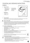
• Loosen lateral casing screws and remove upper part of casing.
• Introduce all connecting cables into the lower casing part
through the cable glands.
• Location of the cable depends on the diameter
of the cables and taking into account the utilization of option
boards and mains power supply and according to the following
recommendations:
Cable glands
1. 쏗 4.25 ± 0.75 mm2 – T. probe (supply)
2. 쏗 4.25 ± 0.75 mm2 – T. probe (return)
3. 쏗 6 ± 1 mm2 – mains power supply – optional
4. 쏗 4.25 ± 0.75 mm2 – optional
5. 쏗 4.25 ± 0.75 mm2 – optional
6. 쏗 6 ± 1 mm2 – T. probe (supply)/optional
7. 쏗 6 ± 1 mm2 – T. probe (return)/optional
8. 쏗 3.75 ± 0.75 mm2 – flow meter
3
1
2
4
5
6
7
8
4.2 Temperature probe
Only use pairs of temperature probes with the same serial number. Probe cables must not be shortened or lengthened. Probes must
be mounted according to the guidelines EN 1434.
Connecting specification:
• Connection
• Cable diameter
• Maximum wire section
• Type
2 wire technology, for CF 55 also 4 wire technology
3.5 mm … 6,5 mm
0.2 … 1.5 mm2
PT100 or PT500 according to DIN EN 60751
Observe nominal value of calculator – cf. nameplate.
4.2.1 Connecting of temperature probes
The following figures (4.2.2 and 4.2.3) and descriptions cover the connection of temperature probes in heating circuits. When
connecting temperature probes in cooling circuits or in combined heat-cooling circuits, please observe the following connecting
instructions:
Warm connector
Cold connector
Heating-heat flow circuit
Cooling circuit
Combined heating-cooling circuit
supply probe
return probe
heating supply probe
return probe
supply probe
heating return probe
• Pierce cable glands 1 and 2 of the calculator
• Pull the supply temperature probe cable (= warmer line)
through cable gland 1 and the return probe
cable (= colder line) through cable gland 2 .
• Make a loop to resist tension and loop over
the corresponding support (cf. figure).
• Connect wires according to the plan of terminal connections.
3