1
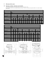
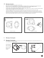
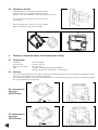
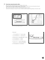
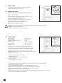
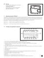
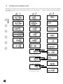
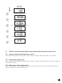
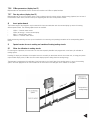
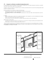
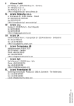
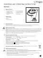
MOUNTING AND OPERATING INSTRUCTIONS
CF Echo II
1.
Metering Unit
Delivery CF Echo II
- Compact heat meter with
removable calculator
- 1 connected flow meter
- 2 temperature sensors
(optional)
- 1 wall mounting bracket
- 1 package with material
for sealing, screws, wall
plugs (6 mm)
- 1 set of gaskets
Required tools
- 3 mm screw driver
- Wrench
- Crosstip screwdriver
Flow Meter
2.
General indications
Heat meter CF Echo II is a sophisticated electronic measuring instrument. The following instructions must be carefully
observed in order to esnure correct mounting and to fulfill all safety and guarantee conditions.
Advice concerning safety
Hot water circuits and mains power supplies run under high temperatures and pressures as well as under high voltages. When
operated incorrectly, these may cause serious injuries. Due to this, the measuring units may only be installed by qualified and
trained personnel. The casings of the heat meters are designed for cold, warm and hot water with the characteristic values
specified for each case, excluding any other liquid. If the integrator casing is submitted to strong shocks, impacts, drops from
more than 60 cm height or similar stresses, the heat meter must be replaced. Pipes must be earthed. Before
opening the meter, mains voltage (optional) must be isolated.
2.2 CE marks and protective classes
•
•
•
•
•
•
•
•
•
Metering unit CF Echo II fulfils all requirements of EC guidelines and is approved for environmental class C
(industrial applications) according to DIN EN 1434:
ambient temperature:
+5 °C … +55 °C (indoors installation)
storage temperature (without battery): -10 °C … +60 °C
relative atmospheric humidity:
< 95 %
absolute altitude:
< 2.000 m
protective class IP 64 according to DIN EN 60529 (protection against dust and splashing); flow meter IP 66/67
EMC protection according to DIN EN 50081-1/2, DIN EN 50082-1/2
double protective insulation
(protective class II according to IEC 60364-4-443)
CF Echo II fulfils the requirements for pressurized instruments guideline (97/23/EG)
concerning specific pressures and temperatures
Discarded electronic devices or batteries contained within the CF Echo II must not be put in normal household
waste. Dispose in accordance to local government regulations.
2.3 Further important instructions
•
•
•
•
•
•
The flow meter must not be lifted or transported by the connecting cable.
Mounting position shall be selected so that the connecting cable of the flow meter and the temperature probe cables will
not lie near mains cables or other sources of electromagnetic disturbances (minimum distance 50 cm.).
Cables must not be installed along pipes reaching temperatures above 55 °C.
Opening of calibration seals will cause the loss of calibration validation and of guarantee, including conformity with
pressurized devices guideline 97/23/EG.
The casing may only be cleaned on the outside with a soft, damp cloth. Do not use detergents.
Installation must be carried out according to DIN 4713 or DIN EN 1434.
1
3.
Mounting the flow meter
3.1
Operating conditions, dimensions and materials
The operating parameters of the heating circuit must no exceed given values:
Nominal pressure 16/25 bars, operating temperature 130 °C, short term maximum temperature 150 °C. For further technical
data cf. table:
Thread connection
Connection
Thread after ISO 228
Transducer materials
Stainless steel
O ring
EPDM
Pipe materials
brass Cu Zn36 Pb2 AS
bronze Cu Pb5 Sn5 Zn5
Nominal flow, qp(Qn) m3/h
0,6
1,5
2,5
3,5
6
Max. flow, qs m3/h
1,2
3
5
7
12
20
6
15
25
35
60
100
Min. flow, qi l/h
Startup flow l/h
1,2
3
5
7
10
12
20
Build in length L1, mm
110
130
190
110
130
190
130
190
260
150
260
150
260
260
200
300
Nominal diameter
15
20
20
15
20
20
20
20
25
25
25
25
25
32
40
40
Thread connection G
G3/4B
G1B
G3/4B
G1B
G1B
G1"1/4B
G1"1/4B
G1"1/4B
G1"1/2B
High A, mm
110
110
110
110
110
110
110
110
114
114
114
114
114
114
123
123
Weight, kg
1,1
1,2
1,5
1,1
1,2
1,5
1,1
1,4
1,9
1,5
1,9
2,4
2
1,8
2,5
5,5
Internal diameter di, mm
19
19
19
19
19
19
20
20
28,5
28,5
28,5
28,5
28,5
28,5
44
44
Pressure loss at qp, bar
0,03
0,03
0,03
0,21
0,21
0,21
0,15
0,15
0,15
0,12
0,12
0,13
0,13
0,13
0,08
0,08
Flange connection
Connection
Flanged after ISO 7005 3, PN 25
Transducer materials
Stainless steel
O ring
EPDM
Pipe materials
brass Cu Zn36 Pb2 AS
Nominal flow, qp(Qn) m3/h
0,6
1,5
2,5
3,5
6
10
Max. flow, qs m3/h
1,2
3
5
7
12
20
30
6
15
25
35
60
100
150
Min. flow, qi l/h
2
G2B
bronze Cu Pb5 Sn5 Zn5
7
12
15
Startup flow l/h
1,2
3
5
Build in length L1, mm
190
190
190
260
300
260
300
270
300
250
20
270
270
30
Nominal diameter
20
20
20
25
40
25
40
50
40
40
50
50
50
High A, mm
110
110
110
114
114
114
114
114
123
123
123
123
123
250
Weight, kg
3,2
3,2
3,2
4,5
7,1
4,5
5,8
8,6
8,2
8
9
9
8,8
Flange Diameter D, mm
105
105
105
115
150
115
150
165
150
150
165
165
165
Bolt circle diameter K, mm
75
75
75
85
110
85
110
125
110
110
125
125
125
Bold holes diameter L,mm
14
14
14
14
18
14
18
18
18
18
18
18
18
Flange dimension F, mm
100
100
100
110
140
110
140
160
140
140
160
160
160
Internal diameter di, mm
19
19
20
28,5
28,5
28,5
28,5
28,5
44
44
44
44
44
Pressure loss at qp, bar
0,03
0,21
0,15
0,12
0,12
0,13
0,13
0,13
0,08
0,08
0,08
0,16
0,16
3.2 Mounting instructions
•
•
•
•
•
•
Never carry out welding or drilling work near the meter.
Leave the meter in its original package until all connections, insulating, painting and cleaning tasks have been performed.
Always install the meter according to the mounting position indicated on the nameplate (supply or return).
The flow meter may be installed either horizontally or vertically, but not upside down.
The heat meter must be protected against shocks and vibrations which might occur at the place of installation. When charging
the pipes with water, isolation valves must be opened slowly.
Thread and flange connections of the meter must match with the nominal width DN and nominal pressure PN
(according to EN 1092) of the corresponding counterparts of the pipes. The metering unit must not be subject to excessive
tensions caused by pipes or molded parts. The pipes of the heating system must be secularly fastened before and after the
flow meter. In case of flange connections, all bolts must be used and tightened. All bolts, nuts and gaskets used must comply
with the nominal width DN, the pressure level PN, the maximum admissible temperature and pressure.
Flow direction, e.g. rising pipe
Flow direction
+ 45°
- 45°
Vertical mounting
4.
4.1
Horiztonal mounting
Mounting of the integrator
Mounting of the integrator
The integrator must not be installed with the flow meter when environmental temperature is permanently above 55 °C or in
case of operation for cooling purposes.
Rotate 45°
Set metering unit
with an angle of
45° on the support
Rotate metering
unit 45° till it
engages.
3
4.2 Mounting on the wall
If temperatures in the heating circuit are permanently
higher than 90 °C, or if ambient temperature is more
than 55 °C, it is recommended to mount the integrator on the wall.
35,2 mm
35 mm
Screw the supplied wall support to the wall or fasten it
to a cool pipe.
Set the integrator with an angle of 45° on the support
Rotate the metering unit by 45° till it engages.
69 mm
Rotate 45°
5.
Mounting of temperature probes (if not already done in factory)
5.1
Technical data
•
•
•
•
Connection
Cable diameter
Maximum wire section
Type
2 wire technology
3.5 mm … 6.5 mm
0.2 … 1.5 mm2
PT 100 or PT 500 according to DIN EN 60751
(Observe nominal value of integrator – cf- nameplate)
5.2 Mounting
Only use pairs of temperature probes with the same serial number. Probe cable must not be shortened or lengthened. Probes
must be mounted according to the guidelines of EN 1434.
For nominal flows Qp 0.6 – 2.5, the return measuring point for direct measuring probes of type DS or for pocket type probes
PS must be integrated in the flow meter.
DS, measurement in
flow meter
(DN 15/20 only)
Gasket
PS, measurement in
flow meter
(DN 15/20 only)
Knurled nut
4
5.3 Connecting temperature probe cables
•
•
•
•
Pierce the first and second cable ducts of the integrator (from the left).
Pull the cable of the supply temperature probe (= warmer pipe) through the first duct and the cable of the return
temperature probe through the second throughput, from the left.
Make a loop to resist tension and loop over the corresponding support (cf. figure).
Connect wires according to the plan of terminal connections (protected against wrong polarity) to the terminal strip.
CF Echo II
Return
Supply
temperature temperature
probe
probe
The color of the wires (polarity) is irrelevant
Cable glands:
1.
4.25 ± 0.75 mm2 – T. probe (supply)
2.
4.25 ± 0.75 mm2 – T. probe (return)
3.
6 ± 1 mm – mains power supply – optional
4.
4.25 ± 0.75 mm2 – optional
5.
4.25 ± 0.75 mm2 – optional
6.
6 ± 1 mm2 – T. probe (supply)/optional
7.
6 ± 1 mm2 – T. probe (return)/optional
8.
3.75 ± 0.75 mm2 – flow meter
2
3
1
2
4
5
6
7
8
5
6.
Power supply
Three types of power supply are available. As standard,
system is fitted with a 6 years battery.
6.1
Lithium
3,6 V-AA
Battery for 6 years*
Type 2 x lithium 3.6 V-AA, soldered to an insert board
•
•
Use only original battery.
Do not recharge, open, heat to more than 100 °C, expose
to an open flame or immerse in water.
Do not dispose through domestic waste.
Dispose in accordance to local government regulations.
Connect battery using plug-in connectors.
Place the battery into the corresponding recess
In the integrator casing and engage.
CAUTION: when the battery has been disconnected more than one minute, it may become
necessary to reset the interior clock.
* Optional: 12 years battery available on request.
•
•
•
•
•
•
Mains voltage
Mains frequency
Maximum power requirement
Type of cable
Cable diameter
Section of wire
230 V ± 15 %
50 Hz ± 2 %
1 VA
2 wires (no earth)
4.5 mm … 7.0 mm
0.5 … 2.5 mm2
Heat meters with mains power supply must be connected
according to installation instructions. The mains power supply
must be protected against voltage failures. Protective systems
(circuit breakers) must be used, in order to ensure secure
disconnection of the unit from the mains in case of electric trouble
(breaking current < 1A).
Mains
module
27 28
6.2 Mains module
An emergency circuit breaker should be:
• installed within reach
• clearly recognizable as an emergency breaker
• cut off both wires
• clearly show the on/off position
•
•
•
•
•
•
•
6
The connecting cable of themains option must be directly connected to the breaker switch.
Cut off grid voltage (breaker switch).
Open meter casing and connect the mains power supply using the plug.
Introduce the mains option board into the corresponding recess in the casing.
Pierce the third cable gland from the right and pull through mains cable.
Clamp the cable using the tension relieving system.
Connect wires to terminals No. 27 and 28 (safe guard against wrong polarity, strip 8 mm of insulation).
Close casing lid and switch on mains voltage.
6.3 Start up
•
•
•
7.
Check all functions, especially the correct display of
temperatures and volume flow.
If the casing was opened:
replace upper part of casing and screw together,
secure screws with users seal (use supplied
plastic seals or wire seals).
Operating instruction CF Echo II
A heat meter is a measuring instrument used to measure the energy released in a heating or cooling system. A compact heat meter
consists of the partial components formed by the pair of temperature probes, the flow meter and the integrator, the complete instrument in itself being subject to compulsory calibration when in commercial utilization. The meter collects the measuring values of the
pair of probes and of the flow meter, permitting the display of diverse data over 3 separate display levels.
Display level 1:
billing level (cumulated energy and volume display)
Display level 2:
service level (actual operating data of the heat meter)
Display level 3:
due date level (13 months values for cumulated energy and volume)
7.1
LC display and signification of segments
1
2
3
4
5
6
14
7
13
12
11
10
9
8
1. Alarm symbol: energy measurement stopped for cause of trouble cf. 7.3.5
2. Dirt alarm: energy measurement continued, cleaning of the flow sensors are necessary
3. Temperatures: appears for temperature related displays or for displays of cooling energy in case of combined
heating/cooling meters.
4. Flow display: permanent symbol: flow is present / flashing symbol: no flow
5. Date & time: representation of date and time indications related to time dependent displays, e.g. due day values and maximum
values.
6. Display level: actually selected display level
7. Unit: physical unit
8. Decimal point
9. Pulse weight of exterior connected water meters (only when a corresponding option board is being used)
10. Maximum value: appears when maximum values are displayed
11. Operating time: appears for operating time display
12. Not used
13. Water meter 1 or 2: display concerns exterior water meter (1 or 2)
7
14. Main display area: 7 digits for the display of all values displaying all cumulated and actual values
7.2
All display levels and displays in detail
Depending on the type of unit, the actual range of display may differ from the one shown here. Pressing of the push button activates
the LC display. Switching of levels is achieved by pressing for 2 sec. of push button
, change of display through short pressing of
push button
Flow
Failure hours
Power
Error code temperature measurement
Volume
Supply temperature
Error code flow measurement
LCD-Test
Return temperature
Energy (MWh, kWh of GJ)
Cooling energy (MWh, GJ or kWh)-optional
Overload times
Water meter 1 – optional
Temperature difference
Mains voltage failure time
Water meter 2 – optional
Operating time
Integrator time and date (optional)
Maximum power display
day + month/year/time
permanent change of display
M Bus primary address
M Bus secondary address
Maximal flow value
day + month /year/ time
permanent change of display
M Bus secondary address
digits 5-8
Maximal temperature
day + month /year/ time
permanent change of display
M Bus baudrate
8
Pulse weight water meter 1/2 (optional)
Due day values energy, month 1 … 13
Due day values cooling energy, month 1 … 13 (optional)
Due day values volume, month 1 … 13
Due day values water meter 1/2 month 1 … 13
(optional)
Software Version
7.3
Indications concerning special display functions (partly optional, depending on type of unit)
7.3.1
Energy and volume index (display levels 1 and 3)
The energy unit is programmed at the factory. As a standard, energy is displayed in MWh, optionally KWh or GJ are possible.
7.3.2 Cooling energy (display level 1)
Display of cumulated cooling energy for energy versions for utilization as combined heating/cooling circuits (please refer to point 9 for
more detailed information).
7.3.3 Water meters 1 and 2 (display level 1)
Display of the meter status of connected supplementary water meters with impulse output, using a corresponding optional board
(please refer to point 8 for more detailed information).
9
7.3.4 Maximum value display (display level 2)
The actual monthly maximum values for power output, flow and flow temperature are displayed with the corresponding time stamp.
Internally, 13 monthly maximum values are stored for each case, which may be read out over the M Bus or the optical interface. The
duration of period to assess the maximum values is 60 minutes. The duration of period may be varied over the M Bus or the optical
interface within a range of 1 min – 1440 min (= 1 day).
7.3.5 Operating trouble alarm (display level 2)
In case of operating trouble, CF Echo II displays a symbol “
”. When this trouble alarm appears, maintenance should be called.
CF Echo II shows detailed information concerning operating troubles in special display levels (cf. description of display).
Display level
operation shut down code
A0 = trouble with temperature recording
1 = supply temperature probe is not connected, pipe is interrupted or broken
2 = return temperature probe is not connected, pipe is interrupted or broken
3 = negative temperature difference; temperature probes were exchanged (except
in case of combined heating/cooling metering)
4 = Analog to digital converter is broken (instrument must be replaced)
Display level
operation shut down code (optional)
A1 = trouble with flow measurement
1 = backflow in meter or in pipe system
2 = air in the pipe system, broken ultrasound probes or very strong deposits on the
probes (cleaning or inspection required)
3 = exceeding the maximum admissible flow
* this message is a warning and does not cause measurement shut down.
4 = connection cable with flow transponder or connection to the ultrasound probes
has been disconnected.
5 = no flow for > 24 hours, but ΔT > 15 K
6 = no data communication between integrator and flow meter
7 = problem with the option board
10
7.3.6 M Bus parameters (display level 2)
Representation of characteristic data for remote data readout over M Bus or optical interface.
7.3.7
Due day values (display level 3)
Representation of 13 end of the month values of the cumulated values for energy, volume, cooling energy (optional) and volume of
the connected water meters, with time stamp and beginning with the value of the previous month.
8.
Insert option boards
The function range of the integrator may be extended for data communication and data remote display by means of inserting
different option boards. The following option boards are available:
•
•
•
•
M Bus + 2 exterior water meters
M Bus and energy + volume remote display
LON + 2 exterior water meters
Modem + 2 exterior water meters
Details concerning mounting and start up are described in the mounting and operating instructions of the corresponding option
boards.
9.
Special version for use in cooling and combined heating/cooling circuits
9.1
Meter for utilization in cooling circuits
For these types of products, the heat meter unit has been especially identified and programmed at the factory for utilization in
cooling systems.
Handling, LC display and utilization of the option boards is essentially in accordance with the heat meter unit, all energy and power
output related display values, M Bus data and remote display impulses being related to cooling energy.
The integrator is programmed for installation of the flow meter in the “warm” pipe of the cooling system (= return of the cooling
system). A version programmed for the installation of the flow meter in the cold pipe also is available as an option.
Su
pply
cold
ur n
Ret
m
war
11
9.2
Integrator for utilization in combined heating/cooling circuits
For these product versions, the integrator has been identified and programmed at the factory especially for utilization in air conditioning systems with combined heating and cooling operation.
Handling, LC display and utilization of the option boards is essentially in accordance with the heat meter. The following special characteristics must be taken into account:
Boundary conditions for the metering of heating and cooling energy
• Heating energy is measured as soon as the temperature difference ΔT exceeds 0.5 K
(ΔT = supply temperature Tv - return temperature Tr).
• Cooling energy is measured as soon as the temperature difference ΔT remains below -0.5 K and flow temperature is less than
25 °C.
LC display
• Display of cooling energy is carried out in a supplementary register in the 1st display level. In order to differentiate from heating
energy, a thermometer symbol being displayed simultaneously.
• 13 due day values (end-of-the-month values) for cooling energy may be called up in the 3rd display level.
Option boards for remote display
• The option board outputs are marked “E” (for energy) and “V” (for volume). For this type of product, pulses proportional to the
cooling energy are output at the cooling energy output marked “V”This type of product is programmed for installation of the flow meter in the return pipe of the air conditioning system (= cold pipe
during operation as heating, warm pipe during operation for cooling). A version programmed for the installation of the flow meter in
the supply pipe also is available as an option.
cold
rn
Retu m
war
ly -
p
Sup
rn Retu
cold
Actaris
Allmess GmbH · Am Voßberg 11
23758 Oldenburg i.H. - Germany
t e l +49 43 61 62 50 00
For more information www.actaris.com
fax +49 43 61 62 52 50
HE-0031.0-EN-11.07 - © Copyright 2007, Actaris reserves the right to change these specifications without prior notice.
ply
Sup
Thank you for reading this data sheet.
For pricing or for further information, please contact us at our UK Office, using the details
below.
UK Office
Keison Products,
P.O. Box 2124, Chelmsford, Essex, CM1 3UP, England.
Tel: +44 (0)1245 600560
Fax: +44 (0)1245 808399
Email: [email protected]
Please note - Product designs and specifications are subject to change without notice. The user is responsible for determining the
suitability of this product.