1
3.
Mounting the calculator
3.1
Mounting instructions
•
•
•
Never carry out welding or drilling work near the meter.
Leave the meter in its original package until all connections, insulating, painting and cleaning tasks have been performed.
Pulse weight and mounting position (supply and return) of the flow meter must agree with data printed on the
nameplate of the CF 51/55.
The calculator must be protected against damages caused by shocks or vibrations which may occur at the mounting site.
Type and basic value of the temperature probes to be connected must agree with the data indicated on the nameplate.
The calculator may be installed optionally on the wall, on a cool pipe or directly on the flow meter when type US Echo II
flow meters are being used.
•
•
•
3.2 Mounting on the wall
If temperatures in the heating circuit are permanently higher than 90 °C, or if ambient temperature is more than 55 °C, it is
recommended to mount the calculator on the wall. Screw the supplied wall support to the wall or fasten it to a cool pipe.
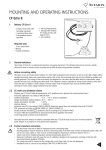
35,2 mm
Set the calculator with an
angle of 45° on the support
35 mm
Rotate calculator 45° until it
engages.
69 mm
3.3 Mounting on flow meter US Echo II
The calculator should not be mounted on the flow meter when ambient temperature is permanently higher than 55 °C or
when cooling operation is being performed.
Rotate 45°
Rotate
45°
Set the calculator with an
angle of 45° on the support
Rotate the calculator 45° till
it engages.
2