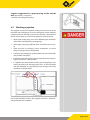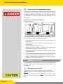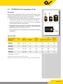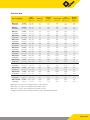
1
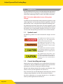
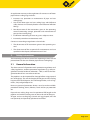
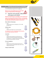
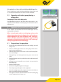
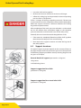
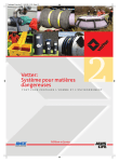
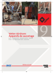
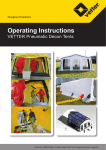
Industrial Pneumatics.
Operating Instructions
VETTER Pipe and Test Sealing Bags
Art.-Nr. 9987044601 | © Vetter GmbH I 06/13 I Changes and errors excepted.
Vetter Pipe and Test Sealing Bags
Contents
1. Introduction. . . . . . . . . . . . . . . . . . . . . . . . . . . . . . . . . . . . . . . . . . . . . . . . . . . . . . 4
1.1
Symbols used. . . . . . . . . . . . . . . . . . . . . . . . . . . . . . . . . . . . . . . . . . . . . . . 4
1.2
Correct handling and usage. . . . . . . . . . . . . . . . . . . . . . . . . . . . . . . . . 4
2. Safety instructions. . . . . . . . . . . . . . . . . . . . . . . . . . . . . . . . . . . . . . . . . . . . . . . . 5
2.1
General information . . . . . . . . . . . . . . . . . . . . . . . . . . . . . . . . . . . . . . . . 5
2.2
Information about the dangers. . . . . . . . . . . . . . . . . . . . . . . . . . . . . . 6
2.3
Warnings. . . . . . . . . . . . . . . . . . . . . . . . . . . . . . . . . . . . . . . . . . . . . . . . . . . 6
3. Operation of Pipe and Test Sealing Bags. . . . . . . . . . . . . . . . . . . . . . . . . . . 7
3.1
Operation with controller, inflation hose and
compressed air bottle. . . . . . . . . . . . . . . . . . . . . . . . . . . . . . . . . . . . . . 7
3.2
Operation with controller, inflation hose and
other compressed air sources . . . . . . . . . . . . . . . . . . . . . . . . . . . . . . . 8
3.3
Operation with a foot pump having a safety valve . . . . . . . . . . . 9
4. Operation of Pipe and Test Sealing Bags. . . . . . . . . . . . . . . . . . . . . . . . . . . 9
4.1
Preparations for operation. . . . . . . . . . . . . . . . . . . . . . . . . . . . . . . . . . 9
4.2
Support structure. . . . . . . . . . . . . . . . . . . . . . . . . . . . . . . . . . . . . . . . . . 10
4.3
Blocking a pipeline . . . . . . . . . . . . . . . . . . . . . . . . . . . . . . . . . . . . . . . . 11
4.4
Emptying the pipeline. . . . . . . . . . . . . . . . . . . . . . . . . . . . . . . . . . . . . 12
4.5
Water test and compressed air test. . . . . . . . . . . . . . . . . . . . . . . . . 12
4.6
Water pressure test (open channel). . . . . . . . . . . . . . . . . . . . . . . . . 12
4.7
Compressed air test. . . . . . . . . . . . . . . . . . . . . . . . . . . . . . . . . . . . . . . . 13
4.8
Construction of a temporary bypass. . . . . . . . . . . . . . . . . . . . . . . . 14
5. Maintenance and care . . . . . . . . . . . . . . . . . . . . . . . . . . . . . . . . . . . . . . . . . . . 14
5.1
Maintenance intervals . . . . . . . . . . . . . . . . . . . . . . . . . . . . . . . . . . . . . 14
6. VETTER Round Profiles. . . . . . . . . . . . . . . . . . . . . . . . . . . . . . . . . . . . . . . . . . . 16
Page 2/32
6.1
Vetter Mini Pipe Sealing Bags 2.5 bar. . . . . . . . . . . . . . . . . . . . . . . 16
6.2
VETTER Mini Test Sealing Bags 2.5 bar. . . . . . . . . . . . . . . . . . . . . . . 17
6.3
Vetter Pipe Sealing Bags 0.5, 1.5 and 2.5 bar . . . . . . . . . . . . . . . . 18
6.4
Vetter Test Sealing Bags 0.5, 1.5 and 2.5 bar. . . . . . . . . . . . . . . . . 20
6.5
Vetter Bypass Bags 1.5 bar. . . . . . . . . . . . . . . . . . . . . . . . . . . . . . . . . 22
6.6
Vetter House connection Testing system 2.5 bar . . . . . . . . . . . . 23
6.7
Vetter Pipe Sealing Bags CR. . . . . . . . . . . . . . . . . . . . . . . . . . . . . . . . 24
6.8
Vetter High Pressure Pipe Sealing Bags 6 bar. . . . . . . . . . . . . . . . 25
7. VETTER Egg Profiles. . . . . . . . . . . . . . . . . . . . . . . . . . . . . . . . . . . . . . . . . . . . . . 26
7.1
Vetter Egg Profile Bags 1 & 1.5 bar. . . . . . . . . . . . . . . . . . . . . . . . . . 26
7.2
Vetter Egg Profile Testing and Bypass bags 1 & 1.5 bar. . . . . . . 28
8. Material and resistance charts. . . . . . . . . . . . . . . . . . . . . . . . . . . . . . . . . . . . 30
8.1
Material list. . . . . . . . . . . . . . . . . . . . . . . . . . . . . . . . . . . . . . . . . . . . . . . . 30
8.2
Temperature resistance. . . . . . . . . . . . . . . . . . . . . . . . . . . . . . . . . . . . 30
8.3
Resistance chart. . . . . . . . . . . . . . . . . . . . . . . . . . . . . . . . . . . . . . . . . . . 31
Important information
Owing to an increase in demand, all pipe and test sealing
bags will be fitted with brass couplings as a standard from
01.01.2012 onwards.
If you still wish to have the safety couplings (blue at 1.5 bar, black at 2.5 bar), we kindly ask you to state this explicitly when placing an order.
Page 3/32
Vetter Pipe and Test Sealing Bags
1.
Introduction
The precondition for the safe use and the defect-free operation of
Vetter pipe and test sealing bags is the knowledge and the observance of this operating manual as well as the safety instructions.
DIN 7716 is to be adhered to in cases of long-term storage.
In addition to this, the pertinent work protection regulations, work
safety regulations and accident prevention regulations are to be
observed the same as the generally recognized technology laws.
The operating instructions given here are to be regarded as part
of the product and are to be kept for the complete life duration of
the product. In case the product should be passed on to a successive user then the operating instructions must also be included.
1.1 Symbols used
The following symbols are used in the text for dangers and warnings:
This symbol means that there is imminent danger. If it is not avoided then
death or serious injury will result.
This symbol means that there is a possible dangerous situation. If it is not
avoided then death or serious injury
could result.
This symbol means that there is possibly a dangerous situation. If it is not avoided then light injuries or slight injuries
could result.
This symbol means that there is the
possibility of damage being caused. If
it is not avoided then the product or
something else in its vicinity could be
damaged.
1.2 Correct handling and usage
Vetter pipe and test sealing bags must, depending on the purpose of the task, only be inflated with compressed air to the corresponding pressure level using original inflation fittings.
Inflation with inflation fittings from another manufacturer is classified as contrary to the regulations for correct use.
They are exclusively used for blocking the intended pipes, for leak
sealing testing of pipelines and for construction of a bypass.
Any other application or use going beyond this is classified as
contrary to the regulations for correct use.
Page 4/32
An application contrary to the regulations for correct use of Vetter
pipe and test sealing bags includes:
99 Incorrect use, operation or maintenance of pipe and test
sealing bags.
99 Use of the Vetter pipe and test sealing bags with defective
safety devices or incorrectly fitted or non-functional inflation
fittings.
99 Non-observance of the instructions given in the operating
manual concerning storage, operation and maintenance of
pipe and test sealing bags.
99 Insufficient monitoring of accessory parts subject to wear.
99 Incorrectly carried out maintenance work.
Correct use according to regulations also includes
99 The observance of all instructions given in this operating manual.
99 The observance of the set periods for maintenance and care
specified in the chapter „Maintenance and Care“.
2.
Safety instructions
The knowledge and observance of this operating manual are the
preconditions for the use of Vetter pipe and test sealing bags
2.1 General information
The observance of all pertinent work protection regulations and
safety regulations, accident prevention regulations (e.g. safety regulations from the technical authorities – TBG) as well as the recognized technical laws are to be carried out.
The pipeline is to be inspected for damage before using pipe and
test sealing bags. The area in the pipe for the pipe and test sealing
bag must be free of deposits, dirt and foreign bodies, such as fragments, sharp-edged objects etc.
Necessary personal protection devices must be made available:
protection clothing, cloves, helmets, facial and/or eye protection
etc.
Pipe and test sealing bags must be positioned full length in the
pipeline and with the sealing area on the inside wall of the pipe.
All pipe and test sealing bags (round and egg-shaped) must be
non-positively and positively positioned and fitted.
Page 5/32
Vetter Pipe and Test Sealing Bags
2.2 Information about the dangers
Changes and modifications to the sealing bags, inflation fittings
and inflation hoses are not permitted. Operation of Vetter pipe
bags, test bags and bypass bags are only permitted with original
Vetter inflation fittings and inflation hoses. Parts made by another
manufacturer can influence safety.
Pipe and test sealing bags are made of a strong expanding material. If this material is expanded beyond its permitted maximum
range then this can cause bursting. No person is allowed to remain within the working area during the pressure test. With a
water pressure test, the pipeline being tested must not have any
direct connection to a high-pressure line (e.g. hydrant).
After positioning the pipe and/or the test sealing bag it is to be
ensured that nobody remain in the channel or in front of the pipe
during inflation, as well as during the test procedure and emptying sequence. Before removing the set-up make certain that the
pipeline is not under any pressure and is completely empty.
2.3 Warnings
The pipe and test sealing bags as well as the accessories must be
checked for perfect condition before and after each operation.
Outside the pipeline, Vetter pipe and test sealing bags, 0.5 bar and
1 bar, must only be filled to maximum 0.2 bar for the visual test.
1.5 bar and 2.5 bar bags must only be filled to a maximum of 0.5
bar.
All controllers are fitted with a safety valve that has a permitted
maximum operating pressure corresponding to the pipe and test
sealing bag. If the maximum operating pressure of 0.5, 1.5, 2.5 or
6 bar is exceeded then the safety valve will activate. The tolerance
for opening and closing of the safety valve is only permitted to be
a maximum of + 10 %. The set pressure must not be changed. If
the sealing on the top part of the valve is removed then its operation is no longer guaranteed and the safety valve must be exchanged. The permitted inlet pressure on the controller (marking
on the inlet coupling) must not be exceeded.
Page 6/32
3.
Operation of Pipe and Test Sealing Bags
This chapter informs you about which compressed air sources you
can use with the Vetter pipe and test sealing bags.
Observe the corresponding pressure level with
operation of pipe and test sealing bags
3.1 Operation with controller, inflation hose and compressed air bottle
Note! In the following presented figures the sequence of
events uses the pressure level of 2.5 bar as an example.
The corresponding bags and accessories must be used
for other pressure levels and other sources of air.
Pipe and test sealing bags
99 Step 1
Connect pipe and test sealing bags 2.5 bar to the
inflation hose.
Inflation hose
99 Step 2
Connect the inflation hose to the controller.
The inflation hose, the sealing bag and the controller
must have the same pressure level.
Controller
99 Step 3
Connect the connection hose of the pressure regulator to the inlet coupling of the controller.
In doing this it is imperative that the permitted inlet
pressure of the controller is observed
Pressure regulator
99 Step 4
Screw-in the connection thread of the pressure regulator into the inside thread of the valve on the
compressed air bottle.
Compressed air bottle
Page 7/32
Vetter Pipe and Test Sealing Bags
3.2 Operation with controller, inflation hose and other compressed air sources
Observe the maximum inlet pressure from the
compressed air source for the different
pressure levels (refer to the table below).
Truck compressed
air connection
Applied pressure level
Maximum inlet pressure
of the compressed air source
0.5 bar
2 bar
1.0 bar
2 bar
1.5 bar
2 bar
2.5 bar
4 bar
Adapters in the adapter set
The adapter set contains adapters for the following air sources:
Truck compressed air connection and dummy coupling
Close the control line with the dummy coupling.
Dummy coupling
Local compressed air network
Connection on the output coupling of a compressed air network.
Truck tyre valve
For inflation with a normal hand pump or foot pump
Truck tyre valve connection
For taping off air from a spare wheel.
Hand pump and foot pump
Hand pump or foot pump with 2 m connection hose to the connection onto the inlet coupling of a controller. Hand pump and
foot pump do not belong to the delivery package of the adapter
set.
Page 8/32
Air supply hose, 10 m, with and without blocking valve
The air supply hoses, with and without blocking valve, can be used
as an extension between the air source and the controller.
3.3 Operation with a foot pump having a safety valve
Foot pump 2.5 bar with safety valve
Foot pump 2.5 bar with safety valve
Foot operated air pump 2.5 bar with safety valve and 2 m connection hose for inflation of sealing bags in connection with an
inflation hose.
4.
Operation of Pipe and Test Sealing Bags
In this chapter you will find out how the Vetter pipe and test
sealing bags are applied.
When using the pipe and test sealing bags, observe the
safety instructions given in chapter 2 as well as the pertinent regulations for work protection and safety protection, accident prevention regulations (e.g. the safety
regulations of the technical authorities -TGB) and the generally recognized laws of technology.
4.1 Preparations for operation
99 Ensure that only authorized staff are in the working area and
danger area.
99 Select a suitable pipe and/or test sealing bag which corresponds to the requirements.
99 Check the bag and the accessories to be used for completeness and damage.
99 Damaged bags and damaged accessory parts must not be
used!
99 The bag diameter must be smaller than the inside diameter of
the pipeline.
99 Inflation hose and controller must already be connected to
the sealing bag.
99 Mark the working area.
99 Position the bag (full length) into the pipe.
99 The sealing bag in the pipe is to be supported.
99 Draw the sealing bag to the support structure and inflate so
that it can still be moved in the pipeline.
99 The support structure should be made so that the sealing bag
can be supported over a large area.
Page 9/32
Vetter Pipe and Test Sealing Bags
99 Leave the shaft and/or pipeline.
99 Make certain that no staff remain in the area of danger.
99 Inflate the sealing bag to the permitted maximum operating
pressure from a safe position.
There is a danger of the bag catapulting outwards. The pressure
or water column must be completely reduced within the pipeline
before the support structure is removed. Otherwise the sealing
bag could catapult outwards.
After completion of the work, pressure reduction is to be carried
out via the inflation hose (ventilation nipple) or the controller
(pressure reduction via the knurled screw of the safety valve).
Generally this must be made outside the pipeline or shaft.
99 If the water has completely flowed out of the shaft / pipeline
then release the compressed air out of the bag.
99 Now remove the support structure and take the bag out of
the shaft/ pipeline.
4.2 Support structure
The type of support structure depends on the structural factors in
the pipe, the pipe itself and the counter-pressure to be expected.
The following support possibilities are only drawing diagrams and
are given as examples.
General details of support (presented as a diagram)
1 Bag centre
2 Inflatable bag sleeve
Support suggestion for a ditch
(presented as a diagram)
Support suggestion for a street inlet shaft
(presented as a diagram)
Page 10/32
Support suggestion for a pipe opening on the outside
wall (presented as a diagram)
1 Outside wall with pipe opening
4.3 Blocking a pipeline
The support structure of a pipeline under pressure must never be
removed. Pipe sealing bags and test sealing bags could suddenly
catapult outwards. During a pressure test nobody is permitted to
remain in the shafts or on and in the pipelines under pressure.
99 Vetter pipe sealing bags are used in different pipe diameters
(refer to the marking on the sealing bags).
99 Select pipe sealing bag, inflation hose, controller and air source.
99 There must be no branches, house connections or similar
things in the pipe area to be blocked.
99 Connect pipe sealing bags to the inflation hose and controller
and position in the pipe.
99 Inflate the pipe sealing bag to the permitted maximum operating pressure from a safe position.
99 If a pipeline has to be blocked with a pipe sealing bag or test
sealing bag then the operating pressure is to be monitored
with the controller (e.g. possible pressure changes caused by
deviations in temperature).
Due to presentation reasons, the support structure is schematically presented and simplified.
Page 11/32
Vetter Pipe and Test Sealing Bags
4.4 Emptying the pipeline
99 It is to be ensured that nobody remains in the shaft or pipe
before emptying the pipeline.
99 Empty the secured sealing bag via the controller so the dammed liquid is able to slowly flow pass the sealing bag and support structure.
99 The support structure or the securing device must only be removed when the pipeline is completely empty.
99 Check the applied bag and its accessories for completeness,
perfect condition and function.
4.5 Water test and compressed air test
99 The data specified in EN 1610 (leak testing) is to be observed
concerning open channels.
99 Using suitable measures, the pipe and test sealing bags are to
be secured against catapulting outwards and slipping.
99 Select the suitable pipe and test sealing bags depending on
the pipe diameter.
99 Filling the pipeline as well as ventilation and measurement of
the test pressure are carried out via the test sealing bag.
99 Blocking is made with the pipe sealing bag
4.6 Water pressure test (open channel)
99 Insert the pipe sealing bag and test sealing bag, including
assembled ventilation swimmer hose, Storz couplings and
blocking valve, into the pipeline, construct the support and
inflate to the permitted operating pressure with the controller
and the inflation hose.
99 Mount the inflation hose on the blocking valve for water filling and connect the test and measurement hose to the second Storz connection and position it vertically upwards out
of the shaft.
99 Attach the marking for the required height of the water column.
99 Filling the pipeline takes place outside the shaft.
99 The test specifications valid at the time of testing are to be
observed (e.g. EN 1610).
99 The pipe and test sealing bags are emptied via their inflation
devices after completion of the water pressure test and complete pressure relief of the pipeline and are then removed out
of the pipeline.
99 This also applies to the support structure.
99 Check the applied bags and their accessories for completeness, perfect condition and function.
Page 12/32
4.7 Compressed air test
The support structure of a pipeline under pressure must never be
removed. Pipe sealing bags and test sealing bags could suddenly
catapult outwards. During a pressure test nobody is permitted to
remain in the shafts or on and in the pipelines under pressure.
99 Insert pipe sealing bag and test sealing bag, including mounted compressed air adapter, into the pipeline and inflate to
the permitted operating pressure with the controller and the
inflation hose.
99 Connect the inflation and safety hose (0.3 bar) (filling the
pipeline to the permitted test pressure) and the measurement
hose (0.3 bar) or, as an example, the measurement hose of the
Vetter manual pressure measurement gauge, to the test adapter of the test sealing bag.
99 The filling of the pipeline to be tested with the pre-specified
permitted test pressure is made outside of the shaft.
99 The testing time is dependent on the pre-specified test method.
99 The applied pipe and test sealing bag can be deflated via their
inflation fittings and taken out of the pipeline after completion of the pressure test and after complete pressure relief of
the pipeline.
99 Check the applied bags and their accessories after use for
completeness, perfect condition and function.
Page 13/32
Vetter Pipe and Test Sealing Bags
4.8 Construction of a temporary bypass
Persons can be endangered by sudden inrushes of water, therefore an additional pipe sealing bag (2) must be installed in order to
ensure the safety of the construction area. The safety regulations
and information issued by the corresponding authorities are to
be observed!
Construction of a temporary bypass
(schematic diagram)
Due to presentation reasons, the support structure and securing
lines are schematically presented and simplified.
99 Fit the corresponding bypass adapter in order to bypass the
sealing bag.
99 Insert the bypass bag (1) at the top of the construction site
into the pipe.
99 Support the bag according to shape.
99 Connect the Storz coupling (A resp. B) to the suction pump
installed above ground via the suction hose.
99 Make certain that the level of dammed liquid does not exceed
5m water column.
99 Connect a hose to the pump on the pressure side and position
it into the pipe system at the back of the construction site.
99 Insert an additional pipe sealing bag (3) in order to avoid a
backflow into the construction area.
5.
Maintenance and care
This chapter gives you information about care of your Vetter pipe
and test sealing bag and the maintenance intervals which must
be observed.
5.1 Maintenance intervals
A function test of the safety valve must only be carried out without the pipe and test sealing bag. Maximum pressure area!
A function test of the safety valve with the pipe and test sealing
bag outside the pipeline or test pipe can cause bursting of the
bag.
Page 14/32
The function test of the pipe and test sealing bag at the maximum
operating pressure in the permitted maximum pipe diameter
must only be carried out in a resistive pipe. A pipe which is too
weak will explode when a bag is inflated to the maximum operating pressure!
When?
What?
What is to be done?
Who?
Before each
use
Pipe and test sealing bags
along with controllers and
inflation hoses
(Safety equipment)
check for completeness
Expert*
Visual check of the pipe and test sealing bags plus the
safety equipment (e.g., changes in form, cracks, fabric
damage, porous surfaces, etc.)
Function check of the safety equipment
After each use
Pipe and test sealing bags
along with controllers and
inflation hoses
(Safety equipment)
If there are any doubts after the visual check of the pipe
and test sealing bags regarding their safety, the bags
should be returned to the manufacturer for an in-depth
function test.
Manufacturer
check for completeness
Expert*
Visual check of the pipe and test sealing bags plus the
safety equipment (e.g., changes in form, cracks, fabric
damage, porous surfaces, etc.)
Function check of the safety equipment
At least once
annually
(otherwise,
according to
BGI 802, it
is no longer
permitted to
use the bags)
Pipe and test sealing bags
along with controllers and
inflation hoses
(Safety equipment)
If there are any doubts after the visual check of the pipe
and test sealing bags regarding their safety, the bags
should be returned to the manufacturer for an in-depth
function test.
Manufacturer
check for completeness
Expert*
Visual check of the pipe and test sealing bags plus the
safety equipment (e.g., changes in form, cracks, fabric
damage, porous surfaces, etc.)
Function check of the safety equipment
If there are any doubts after the visual check of the pipe
and test sealing bags regarding their safety, the bags
should be returned to the manufacturer for an in-depth
function test.
Manufacturer
If any kind of doubts concerning the safety arise during the visual
check or function check, abort the test and send the bag including the equipment to the manufacturer for further testing.
* An expert is a person who, based on his technical training and
experience, has sufficient knowledge in the sector of pipe-sealing
devices and is so familiar with the relevant governmental occupational safety regulations, accident prevention regulations and
generally accepted laws of engineering (e.g., BG rules, DIN and EN
standards, technical rules from other EU member states or other
contracting states of the Treaty on the European Economic Area)
that he can assess the safe working condition of the pipe-sealing
devices. Source: BGI 802
Document and retain the
test results.
Page 15/32
Vetter Pipe and Test Sealing Bags
6.
VETTER Round Profiles
6.1 Vetter Mini Pipe Sealing Bags 2.5 bar
Description
Due to their design, Vetter mini pipe sealing bags 2.5 bar can be used
in house connection lines, oil and petrol collectors and in front of curves.
99 Connect the inflation hose to the connection coupling of the selected mini pipe sealing bag 2.5 bar and the output coupling of
the controller.
99 The air supply can be made by hand pump, foot pump, pressure
regulator and compressed air bottle or by a local compressed air
supply line, resp. by tapping air from a truck compressed air brake device.
99 Another possibility is the use of a foot air pump with a 2.5 bar
safety valve.
99 Insert or shift the sealing bag to the selected position and inflate
it to the permitted operating pressure of 2.5 bar.
99 The mini pipe sealing bag must be positioned along its whole
length on the pipe wall.
99 Securing lines can be used for removing the pipe sealing bag after work has finished.
Technical data
Diameter
Cylinder
length
mm / inch
mm / inch
mm / inch
litres / cu. ft.
kg / lbs
25 - 40
0.98 - 1.6
21
0.9
115
4.5
175
7
0.7
0.02
0.15
0.33
40 - 70
1.6 - 2.8
37
1.5
155
6.1
215
8.5
2.5
0.09
0.2
0.44
80 - 150
3.1 - 5.9
72
2.8
120
4.7
170
7
11
0.39
0.4
0.88
100 - 150
3.9 - 5.9
89
3.5
130
5.1
175
7
9
0.32
0.56
1.23
125 - 200
5 - 7.8
115
4.5
125
5
175
7
16
0.56
0.76
1.68
150 - 200
5.9 - 7.8
90
3.5
150
5.9
195
7.6
13
0.46
0.6
1.32
150 - 300
5.9 - 11.8
145
5.7
200
8
245
9.7
72
2.54
1.42
3.13
Mini Pipe Sealing
Pipe diameter
Bags 2.5 bar /
36.25 psi
mm / inch
RDK 2.5/4
1440000101
RDK 4/7
1440000201
RDK 8/15
1440018800
RDK 10/15
1440010500
RDK 12.5/20
1440010700
RDK 15/20
1440018900
RDK 15/30
1440010600
Air
Total length requirement
Weight,
approx.
Standard test counterpressure of 10 m WC / 14.5 psi.
All rights reserved for technical changes within the scope of product improvement.
Page 16/32
6.2 VETTER Mini Test Sealing Bags 2.5 bar
Description
Vetter mini test sealing bags 2.5 bar can be used for testing, sealing
and bypassing with repairs and maintenance work, e.g. sealing tests,
channel inspection, maintenance, repair and cleaning.
99 Please observe the permitted maximum counter-pressure of 5 m
water column, resp. 0.5 bar, when using mini test sealing bags.
99 Connect the inflation hose, 2.5 bar, to the mini test sealing bags
and the single controller, 2.5 bar fitting.
99 Position the mini test sealing bag, along its whole length, into
the pipeline and suitably secure it, e.g. with a structure support,
depending on the work to the carried out.
99 Inflation of the mini test sealing bag can be carried out according
to chapter 4.
Technical data
Mini Test Sealing
Bags 2.5 bar /
36.25 psi
PDK 4/7
1441000701
PDK 10/15
1441035400
PDK 12.5/20
1441035200
PDK 20/30
1441035300
Pipe
diameter
Diameter
mm / inch
mm / inch
mm / inch
mm / inch
litres / cu. ft.
kg / lbs
6 mm
0.2 inch
40 - 70
1.6 - 2.8
37
1.5
155
6.1
250
9.8
3.5
0.12
0.4
0.9
1/2“
100 - 150
3.9 - 5.9
90
3.5
150
5.9
300*
11.8*
2
0.07
1
2.2
1/2“
125 - 200
5 - 7.8
115
4.5
150
5.9
300*
11.8*
4,4
0.16
1.2
2.6
1“
200 - 300
7.8 - 11.8
185
7.2
250
9.8
410*
16*
18
0.64
4.5
9.9
Duct
Cylinder
length
Air
Total length requirement
Weight,
approx.
* including valve connection
Standard test counterpressure of 10 m WC / 14.5 psi.
All rights reserved for technical changes within the scope of product improvement.
Page 17/32
Vetter Pipe and Test Sealing Bags
6.3 Vetter Pipe Sealing Bags 0.5, 1.5
and 2.5 bar
Description
Vetter pipe sealing bags 0.5, 1.5 and 2.5 bar can be used for sealing
off pipelines and channelling in connection with repair work
and maintenance, e.g. channel inspection, maintenance, repair,
cleaning etc.
99 When selecting the pipe sealing bag please observe the pressure level and the counterpressure resulting from this (refer to
Technical Data).
99 0.5 bar pipe sealing bags RDK 140/170 and 170/200 cm can
be folded in the deflated condition so that they can then be
inserted into a standard shaft having an opening of 600 mm.
99 Connect the inflation hose(s) to the pipe sealing bag and the
single or double controller of the selected pressure level.
99 Position the pipe sealing bag, along its whole length, into the
pipeline and suitably secure it, e.g. with a structure support,
depending on the work to the carried out.
99 Inflation of the pipe sealing bag can be carried out according
to chapter 4.
Page 18/32
Technical data
Pipe
diameter
Diameter
Cylinder
length
mm / inch
mm / inch
mm / inch
mm / inch
litres / cu. ft.
kg / lbs
2.5 bar
(36.25 psi)
25 - 40
0.98 - 1.6
21
0.9
115
4.5
175
7
0.7
0.02
0.15
0.33
2.5 bar
(36.25 psi)
40 - 70
1.6 - 2.8
37
1.5
155
6.1
215
8.5
2.5
0.09
0.2
0.44
2.5 bar
(36.25 psi)
70 - 150
2.8 - 5.9
68
2.7
300
12
345
13.6
13.3
0.47
0.5
1.1
2.5 bar
(36.25 psi)
100 - 200
3.9 - 7.8
90
3.5
510
20
555
21.9
40.3
1.4
1.2
2.7
2.5 bar
(36.25 psi)
150 - 300
5.9 - 11.8
145
5.7
460
18.1
505
20
87.5
3.1
1.9
4.2
2.5 bar
(36.25 psi)
200 - 400
7.8 - 16
195
7.7
650
25.6
700
27.3
224
7.9
2.8
6.2
2.5 bar
(36.25 psi)
200 - 500
7.8 - 20
195
7.7
750
29.3
795
31
329.0
11.6
5
11
2.5 bar
(36.25 psi)
300 - 600
11.8 - 23.4
295
11.6
735
28.9
780
30.7
507.5
17.9
7
15.4
2.5 bar
(36.25 psi)
500 - 800
20 - 31.5
450
17.7
1,110
43.7
1,155
45.6
2,135
75.4
17
37.5
2.5 bar 600 - 1,000
(36.25 psi) 23.4 - 39.4
580
22.8
1,320
52
1,365
53,7
3,465
122.3
25
55
1.5 bar
(21.75 psi)
500 - 1,000
20 - 39.4
450
17.7
1,110
43.7
1,155
45.6
1,525
53.8
17
37.5
1.5 bar
(21.75 psi)
600 - 1,200
23.4 - 47.2
580
22.8
1,320
52
1,365
53.7
2,475
87.4
25
55
1.5 bar
(21.75 psi)
800 - 1,400
31.5 - 55.1
785
30.9
1,810
71.3
1,855
73
3,125
110.3
41
90.4
0.5 bar 1,400 - 1,700
(7.25 psi)
55.1 - 67
1,350
53.2
1,900
74.8
2,150
84.7
8,700
307.1
55
121.3
0.5 bar 1,700 - 2,000
(7.25 psi)
67 - 78.7
1,620
63.8
1,900
74.8
2,300
90.6
9,000
317.7
59
130.1
Pipe Sealing Bags
RDK 2.5/4
1440000101
RDK 4/7
1440000201
RDK 7/15
1440000301
RDK 10/20
1440011700
RDK 15/30
1440000601
RDK 20/40
1440020100
RDK 20/50
1440016700
RDK 30/60
1440000801
RDK 50/80
1440020000
RDK 60/100
1440011900
RDK 50/100
1480000801
RDK 60/120
1480001901
RDK 80/140
1480006000
RDK 140/170
1400000300
RDK 170/200
1400000100
Air
Total length requirement
Weight,
approx.
RDK 2.5 bar / 36.25 psi - Test counterpressure 10 m WC / 14.50 psi
RDK 1.5 bar / 21.75 psi - Test counterpressure 5 m WC / 7.25 psi
RDK 0.5 bar / 7.25 psi - Test counterpressure 2 m WC / 2.90 psi
All rights reserved for technical changes within the scope of product improvement.
Page 19/32
Vetter Pipe and Test Sealing Bags
6.4
Vetter Test Sealing Bags 0.5, 1.5 and 2.5 bar
Pressure test with air
PDK 60/120 with a duct and compressed air adapter 2“ in a concrete pipe DN 1200 mm.
The required securing of the test bag using a
structure support has been omitted for
presentation reasons.
Description
Vetter test sealing bags 0.5, 1.5 and 2.5 bar can be used for testing, sealing and bypassing with repairs and maintenance work,
e.g. sealing tests, channel inspection, maintenance, repair and
cleaning.
99 When selecting the pipe sealing bag please observe the pressure level and the counterpressure resulting from this (refer to
Technical Data).
99 0.5 bar test sealing bags RDK 140/170 and 170/200 cm can
be folded in the deflated condition so that they can then be
inserted into a standard shaft having an opening of 600 mm.
Test sealing bags can be supplied with one or two ducts for the
water test or the compressed air test. Adapters and accessories for
the water test and the com-pressed air test can also be supplied
(refer to the catalogue).
99 Connect the inflation hose(s) to the test sealing bag and the
single or double controller of the selected pressure level.
99 Position the test sealing bag, along its whole length, into the
pipeline and suitably secure it, e.g. with a structure support,
depending on the work to the carried out.
99 Inflation of the test sealing bag can be carried out according
to chapter 4.
Page 20/32
Technical Data
Pipe
diameter
Diameter
Cylinder
length
mm / inch
mm / inch
mm / inch
mm / inch
litres / cu. ft.
kg / lbs
2.5 bar
70 - 150
2.8 - 5.9
68
2.7
350
13.7
395
15.4
14
0.5
1.7
3.8
2.5 bar
(36.25 psi)
100 - 200
3.9 - 7.8
90
3.5
510
20
555
21.9
40.3
1.4
2.8
6.2
150 - 300
5.9 - 11.8
145
5.7
460
18.1
505
20
87.5
3.1
5.8
12.8
200 - 400
7.8 - 16
195
7.7
640
25
685
26.7
225
7.9
8
17.6
200 - 500
7.8 - 20
195
7.7
750
29.3
795
31
333
11.8
7-9
15.4 - 19.8
300 - 600
11.8 - 23.4
295
11.6
735
28.9
815
32.1
471
16.6
11 - 12
24.3 - 26.5
500 - 800
20 - 31.5
450
17.7
1,110
43.7
1,155
45.6
2,065 - 2,135
72.9 - 75.4
27 - 36
59.5 - 79.4
580
22.8
1,320
52
1,365
53.7
3,395 - 3,430
119.8 - 121.1
33.5 - 42
73.9 - 92.6
500 - 1,000
20 - 39.4
450
17.7
1,110
43.7
1,155
45.6
1,475 - 1,525
52.1 - 53.8
27 - 36
59.5 - 79.4
600 - 1,200
23.4 - 47.2
580
22.8
1,320
52
1,365
53.7
2,425 - 2,450
85.6 - 86.5
33.5 - 42
73.9 - 92.6
800 - 1,400
31.5 - 55.1
785
30.9
1,810
71.3
1,855
73
3,075 - 3,100
108.5 - 109.4
55 - 69
121.3 - 152.2
0.5 bar
1,400 - 1,700
(7.25 psi)
55.1 - 67
1,350
53.2
1,900
74.8
2,150
84.7
8,670 - 8,685
306.1 - 306.6
62.5 - 70
137.8 - 154.4
0.5 bar
1,700 - 2,000
(7.25 psi)
67 - 78.7
1,620
63.8
1.,00
74.8
2,300
90.6
8,775 - 8,888
309.8 - 313.8
64.5 - 70
142.2 - 154.4
Test Sealing Bags
PDK 7/15 FLEX
1441001201 1 x 1/2“ AG (36.25 psi)
PDK 10/20 FLEX
1441018501 1 x 1“ AG
PDK 15/30 FLEX
2.5 bar
1441022700 2 x 1/2“ AG (36.25 psi)
1441022800 1 x 2“ AG
PDK 20/40 FLEX
1441040300 2 x 1“ AG
1441018600 1 x 2“ AG
PDK 20/50 FLEX
1441031100 2 x 1“ AG
1441031200 1 x 2“ AG
PDK 30/60 FLEX
1441023100 2 x 1“ AG
1441018701 1 x 2“ AG
PDK 50/80 FLEX
1441003900 1 x 2“ AG
1441003800 2 x 2“ AG
PDK 60/100 FLEX
1441023200 1 x 2“ AG
1441023300 2 x 2“ AG
PDK 50/100 FLEX
1481003501 1 x 2“ AG
1481023800 2 x 2“ AG
PDK 60/120 FLEX
1481009501 1 x 2“ AG
1481009301 2 x 2“ AG
PDK 80/140 FLEX
1481024000 1 x 2“ AG
1481023900 2 x 2“ AG
PDK 140/170 FLEX
1401000400 1 x 2“ AG
1401000300 2 x 2“ AG
PDK 170/200 FLEX
1401000700 1 x 2“ AG
1401000600 2 x 2“ AG
2.5 bar
(36.25 psi)
2.5 bar
(36.25 psi)
2.5 bar
(36.25 psi)
2.5 bar
(36.25 psi)
2.5 bar
600 - 1,000
(36.25 psi)
23.4 - 39.4
1.5 bar
(21.75 psi)
1.5 bar
(21.75 psi)
1.5 bar
(21.75 psi)
Air
Total length requirement
Weight,
approx.
PDK 2.5 bar / 36.25 psi - Test counterpressure 10 m WC / 14.50 psi
PDK 1.5 bar / 21.75 psi - Test counterpressure 5 m WC / 7.25 psi
PDK 0.5 bar / 7.25 psi - Test counterpressure 2 m WC / 2.90 psi
All rights reserved for technical changes within the scope of product improvement.
Page 21/32
Vetter Pipe and Test Sealing Bags
6.5 Vetter Bypass Bags 1.5 bar
Description
Vetter 1.5 bar bypass bags can be used for creating a bypass with
defective channels. They can also be used for channel repairs and reconstruction as two-sided, temporary blocking with conduction and
pressure relief from the incoming pipeline to the outgoing pipeline.
99 Please observe the permitted maximum counter-pressure of 5 m
water column, resp. 0.5 bar, when using bypass bags.
99 Connect the inflation hose, 1.5 bar, to the bypass bag and the
single controller, 1.5 bar fitting.
99 Insert the bypass bag along its full length into the pipeline and
secure it against catapulting out using suitable devices, e.g. a
structure support.
99 Inflation of the bypass bag can then be made as described in
chapter 4.
Technical Data
Pipe
diameter
Diameter
Cylinder
length
mm / inch
mm / inch
mm / inch
mm / inch
litres / cu. ft.
kg / lbs
PDK 10/20 PE core
100 - 200
3.9 - 7.8
97
3.9
485
19.1
545
21.7
27
0.95
2.2
4.9
PDK 20/50 PE core
200 - 500
7.8 - 20
195
7.7
550
21.7
610
24
143
5
7
15.4
PDK 50/80 PE core*
500 - 800
20 - 31.5
450
17.7
565
22.2
580
22.8
310
10.9
32
70.6
PDK 50/120 PE core*
500 - 1.200
20 - 47.2
450
17.7
920
36.2
935
36.8
1,420
50.1
42.5
93.7
Bypass Bags
1.5 bar / 21.75 psi
1481004400 1 x 2 1/2“ AG
1481005000 1 x 4“ AG
1481006900 1 x 4“ AG
1481008000 1 x 4“ AG
Air
Total length requirement
Weight,
approx.
* A 6“ or 8“ duct can be supplied when required.
Standard test counterpressure of 5 m WC / 7.25 psi.
All rights reserved for technical changes within the scope of product improvement.
Page 22/32
6.6 Vetter House connection Testing system 2.5 bar
Set 10/20 FLEX for water pressure
testing and compressed air testing
Description
Vetter house connection systems are used for leak testing of house
connections. Blocking work and the test sequence are normally carried out from the inspection shaft or from the inspection opening.
99 The pipe test sealing bag is pushed through the pipeline up to
the main channel using the thrust hose.
99 Inflation of the pipe sealing bag is made by the foot operated air
pump 2.5 bar which is contained in the set.
99 The test sealing bag is then positioned at the exit side of the inspection shaft or the inspection opening and is also inflated with
the foot operated air pump 2.5 bar.
99 The safety valve on the foot operated air pump avoids any unintentional overinflation above the permitted operating pressure.
99 The thrust hose is pulled tight after checking for a firm seating
of the test sealing bag and is sealed by tightening the union nut
with the appropriate spanner.
The test set 10/20 Flex can be used for the compressed air test as well
as the water pressure test. With this set there is an additional tapered
head mounted on the thrust hose in front of the pipe sealing bag
which enables retraction of the inserted pipe sealing bag even over
sleeve displacements.
A blocking valve with a bayonet coupling for inflation, an adapter
and a test and measurement hose are supplied for water pressure
testing.
The compressed air test can be carried out with the supplied accessories according to the requirements specified in EN 1610.
Technical Data
House connection
Testing system
2.5 bar / 36.25 psi
RDK 8/15
1440001200
RDK 15/20
1440001300
PDK 10/20 FLEX
1441007703
Pipe
diameter
Diameter
C ylinder
length
Air
Total length requirement
Weight,
approx.
mm / inch
mm / inch
mm / inch
mm / inch
litres / cu. ft.
kg / lbs
80 - 150
3.1 - 5.9
150 - 200
5.9 - 7.8
100 - 200
3.9 - 7.8
72
2.8
90
3.5
90
3.5
120
4.7
150
5.9
300
11.8
165
6.5
190
7.4
460*
18*
11
0.39
13
0.46
18
0.54
0.3
0.7
0.5
1.1
3.1
6.8
* incl. valve connection
Standard test counterpression of 10 m WC / 14.5 psi.
All rights reserved for technical changes within the scope of product improvement.
Page 23/32
Vetter Pipe and Test Sealing Bags
6.7 Vetter Pipe Sealing Bags CR
Description
Vetter pipe sealing bags CR can be floated into the pipeline with the
liquid flow. The material ensures good resistance against chemicals.
99 Connect the inflation hose(s) to the pipe sealing bag CR and the
single or double controller of the selected pressure level.
99 Attach the spring hooks of the securing lines to the securing
lugs.
99 Position the pipe sealing bag CR in the direction of flow into a
shaft and let it float with the liquid flow into the pipe.
99 In doing this, observe the selected diameter and the buoyancy of
the sealing bag.
99 When the sealing bag has been floated in to its full length then
inflation can begin as described in chapter 4.
99 The pipe sealing bag CR is to be fastened during the float-in procedure and the inflation sequence.
99 Final securing of the bag is only made when the permitted maximum operating pressure is reached.
Technical Data
Pipe
diameter
Diameter
Cylinder
length
mm / inch
mm / inch
mm / inch
mm / inch
litres / cu. ft.
kg / lbs
2.5 bar
(36.25 psi)
70 - 150
2.8 - 5.9
68
2.7
300
11.8
345
13.4
14
0.5
0.6
1.3
2.5 bar
(36.25 psi)
150 - 300
5.9 - 11.8
145
5.7
465
18.1
510
20
80
2.8
2.5
5.5
2.5 bar
(36.25 psi)
300 - 600
11.8 - 23.4
295
11.6
735
28.9
780
30.4
508
18
7.3
16.1
1.5 bar
(21.75 psi)
600 - 1,200
23.4 - 47.2
580
22.8
1,320
52
1,365
53.7
2,475
87.4
27
59.5
Pipe Sealing Bag CR
RDK 7/15
1440008100
RDK 15/30
1440008000
RDK 30/60
1440007900
RDK 60/120
1480004800
Air
Total length requirement
Weight,
approx.
RDK 2,5 bar / 36.25 psi - Test counter pressure 10 m WC / 14.50 psi
RDK 1,5 bar / 21.75 psi - Test counter pressure 5 m WC / 7.25 psi
All rights reserved for technical changes within the scope of product improvement.
Page 24/32
6.8 Vetter High Pressure Pipe Sealing Bags 6 bar
Description
Vetter high pressure pipe sealing bags 6 bar can be used in pipelines
having a high internal pressure. These pipe sealing bags can be used
up to a counter-pressure of maximum 30 m water column, resp. 3 bar.
The high pressure pipe sealing bag must be positioned along its
whole length on the pipe wall and be secured against catapulting
outwards using suitable means (e.g. support structure).
A pipeline can burst!
It is imperative that the resistance of the pipeline be tested before
using the high pressure pipe sealing bag due to the fact that the
sealing bag produces a maximum area pressure of 6 kg/cm².
99 Connect the inflation hose to the pipe sealing bag and then to
the controller 6 bar (a double controller 6 bar with two inflation
hoses can be used from DN 500 mm onwards).
99 Check for perfect locking of the nipple into the coupling.
99 The air supply can then be turned on (as described in chapter 4).
99 Insert the high pressure pipe sealing bag into the pipeline.
99 Inflate the high pressure pipe sealing bag with controller and inflation hose until the permitted operating pressure of maximum
6 bar is reached.
Technical Data
High Pressure Pipe
Sealing Bags
RDK 100-200
1430001300
RDK 200-300
1430001500
RDK 300-400
1430001400
RDK 500-600
1430000600
RDK 800
1430000800
Pipe
diameter
Diameter
Cylinder
length
Air
Total length requirement
Weight,
approx.
mm / inch
mm / inch
mm / inch
mm / inch
litres / cu. ft.
kg / lbs
100 - 200
3.9 - 7.8
90
3.5
510
20
555
21.9
105
3.7
1.5
3.3
200 - 300
7.8 - 11.8
195
7.7
650
25.6
695
27.4
338
11.9
3.1
6.8
300 - 400
11.8 - 16
295
11.6
735
29
780
30.7
527
18.6
7
15.4
500 - 600
20 - 23.4
450
17.7
1,110
43.7
1,155
45.5
1,550
54.7
20
44.1
800
31.5
785
30.9
1,810
71.3
1,855
73
6,160
217.5
44
97
Standard test counterpressure of 30 m WC / 43.5 psi.
All rights reserved for technical changes within the scope of product improvement.
Page 25/32
Vetter Pipe and Test Sealing Bags
Egg profile sealing bag 1 bar
7.
VETTER Egg Profiles
7.1 Vetter Egg Profile Bags 1 & 1.5 bar
Description
Egg profile sealing bag 1.5 bar
Vetter egg profile sealing bags 1 and 1.5 bar can be used for blocking egg-shaped pipelines and channel lines during repair and
maintenance work, e.g. channel inspection, maintenance and
cleaning.
99 Please observe the specified sizes of egg profile bags: e.g. EDK
60/90 – the first number is the diameter in cm of the upper
area of the profile, the second number gives the size of the
inside height of the egg profile in cm (refer to the drawing
below).
99 Also please observe the permitted maximum counter-pressure of 5 m water column, resp. 0.5 bar, when using the egg
profile sealing bag.
Vetter egg profile sealing bags 1 bar can be folded in the deflated
condition so that they are able to be inserted through a standard
shaft opening of 600 mm.
The egg profile sealing bag EDK 35/52.5 –50/75 1.5 bar can be
used for a number of profile sizes.
Egg profile sealing bags 1 bar are used for the specified size.
99 Connect the 1.5 bar inflation hose (plug-in nipple/coupling)
or 1 bar inflation hose (claw coupling) to the connection coupling of the egg profile sealing bag 1.5 bar, resp. 1 bar, and
also to the 1.5 bar, resp. 1 bar, connection nipple/coupling of
the controller.
99 Position the whole length of the sealing bag into the pipeline
and secure it with a suitable device, e.g. with a structure support, in order to stop it from catapulting outwards.
99 Inflation of the sealing bag can then be made according to
description given in chapter 4.
Page 26/32
Technical Data
Pipe crosssection
Cylinder
length
mm / inch
mm / inch
mm / inch
litres / cu. ft.
kg / lbs
1.5 bar 350/525 - 500/750
(21.75 psi)
14/21 - 20/30
600
23.4
645
25.4
250
8.8
8
17.6
1 bar
(14.5 psi)
600/900
23.4/35
1,200
47.2
1,400
55.1
840
29.7
17
37.5
1 bar
(14.5 psi)
700/1,050
28/41
1,200
47.2
1,450
57.1
1,400
49.4
20
44.1
1 bar
(14.5 psi)
900/1,350
35/53
1,800
70.2
2,200
86.6
2,640
93.2
26
57.3
Egg Profile Bags
1 & 1.5 bar
EDK 35/52.5 - 50/75
1420000101
EDK 60/90
1420000300
EDK 70/105
1420000400
EDK 90/135
1420000500
Air
Total length requirement
Weight,
approx.
Standard test counterpressure of 5 m WC / 7.25 psi
All rights reserved for technical changes within the scope of product improvement.
Page 27/32
Vetter Pipe and Test Sealing Bags
Egg profile base bag 1bar
7.2 Vetter Egg Profile Testing and
Bypass bags 1 & 1.5 bar
Description
Vetter egg profile bags and bypass bags 1 and 1.5 bar can be used
for blocking and bypassing when carrying out repair and maintenance work, e.g. leak testing, channel inspection, maintenance
and repair as well as cleaning work.
Egg profile bag 1.5 bar
99 Please observe the permitted maximum counter-pressure of
5 m water column, resp. 0.5 bar, when using the egg profile
sealing bag.
Vetter egg profile bags can be folded in the deflated condition so
that they are able to be inserted through a standard shaft opening of 600 mm. Egg profile bags and bypass bags 1 and 1.5 bar
can be supplied with one or two ducts for the water test and the
compressed air test.
Adapters and accessories for water testing and compressed air
testing can also be supplied (refer to the catalogue).
99 The egg profile sealing bag and bypass bag EDK 35/52.5
–50/75, 1.5 bar, can be used for a number of profile sizes. Egg
profile sealing bags 1 bar are each used for the specified size.
99 Connect the 1.5 bar inflation hose (plug-in nipple/coupling)
or the 1 bar inflation hose (claw coupling) to the 1.5 bar (plugin coupling) or the 1 bar (claw coupling) connection coupling
of the egg profile test bag and the connection nipple/coupling of the 1.5 bar or 1 bar controller.
99 Insert the whole length of the test bag into the pipeline and
secure it with a suitable device against catapulting outwards,
e.g. with a structure support.
99 Inflation of the test bag is then made according to the description given in chapter 4.
Page 28/32
Technical Data
Egg Profile Testing
and Bypass bags
EPK 35/52.5 - 50/75
1421000101 1 x 1“ AG
EPK 60/90
1421001300 1 x 2“ AG
1421001200 2 x 2“ AG
EPK 70/105
1421001700 1 x 2“ AG
1421001600 2 x 2“ AG
EPK 90/135
1421002000 1 x 2“ AG
1421001900 2 x 2“ AG
Pipe crosssection
Cylinder
length
mm / inch
mm / inch
mm / inch
litres / cu. ft.
kg / lbs
600
23.4
645
25.4
225
7.9
12
26.5
600/900
23.4/35
1,200
47.2
1,400
55.1
820
29
26 - 35
57.3 - 77.2
700/1,050
28/41
1,200
47.2
1,450
57.1
1,380
48.7
29 - 38
63.9 - 83.8
900/1,350
35/53
1,800
70.2
2,200
86.6
2,620
92.5
36 - 46
79.4 - 101.4
1.5 bar 350/525 - 500/750
(21.75 psi)
14/21 - 20/30
1 bar
(14.5 psi)
1 bar
(14.5 psi)
1 bar
(14.5 psi)
Air
Total length requirement
Weight,
approx.
Standard test counterpressure of 5 m WC / 7.25 psi
All rights reserved for technical changes within the scope of product improvement.
Page 29/32
Vetter Pipe and Test Sealing Bags
8.
Material and resistance charts
8.1 Material list
Products
Manufacturing
process
Material
Support material
NR
Nylon cord
Hot vulcanised
NR
NR
Hot vulcanised
NR
Nylon cord /
Aramide
Hot vulcanised
CR/NR
Nylon cord /
Aramid
Hot/Cold vulcanised
CR
Nylon cord
Hot vulcanised
EPDM
Polyester
-
Mini pipe sealing bag
High pressure pipe sealing bag
Egg profile sealing bag 1.5 bar
Egg profile test sealing bag 1.5 bar
Mini test sealing bag
Pipe sealing bag 1.5 bar
Pipe sealing bag 2.5 bar
Test sealing bag 1.5 bar
Test sealing bag 2.5 bar
Bypass bag 1.5 bar
Pipe sealing bag 0.5 bar
Test sealing bag 0.5 bar
Egg profile sealing bag 1 bar
Egg profile test sealing bag 1 bar
Egg profile bypass bag 1 bar
Pipe sealing bag CR
Inflation and air supply hoses
8.2 Temperature resistance
Cold
Cold
resistance flexibility
Heat resistance
long term
Heat resistance
short term
- 40° C
- 20° C
+ 90° C
+ 115° C
Egg profile sealing bag 1 bar
Egg profile test sealing bag 1 bar
Egg profile bypass bag 1 bar
- 40° C
- 20° C
+ 70° C
+ 85° C
Rubber hoses
- 40° C
- 30° C
+ 90° C
--
Controllers:
Plastic, aluminium and fitting
construction type
- 20° C
--
+ 50° C
--
Products
Mini pipe sealing bags
Mini test sealing bags
Pipe sealing bag 1.5 bar
Pipe sealing bag 2.5 bar
Test sealing bag 1.5 bar
Test sealing bag 2.5 bar
Bypass bag 1.5 bar
Pipe sealing bag CR
High pressure pipe sealing bag
Egg profile sealing bag 1.5 bar
Egg profile test sealing bag 1.5 bar
Pipe sealing bag 0.5 bar
Test sealing bag 0.5 bar
Page 30/32
8.3 Resistance chart
CR
Material
NR
EPDM
Acetone
o
+
-
Acetylene
+
+
-
Alum watery
+
+
-
Aluminum chloride
+
+
+
Aniline
-
n.d.
n.d.
ASTM Oil 1
o
-
-
Petrol
o
-
n.d.
Description of material
Benzene
-
-
-
Boric acid
+
+
+
Bromine (moist)
-
-
-
Butyric acid
-
-
n.d.
Chlorine gas (moist)
-
-
n.d.
Chorine, wet
o
-
0
Diesel fuel
o
-
-
Iron chloride
+
+
+
Crude oil
o
-
-
Acetic acid
o
+
o
Fatty acid
+
o
-
Formaldehyde
+
+
+
Glucose
+
+
+
Heating oil
+
-
-
Potassium chloride
+
+
+
Calcium chloride
+
+
+
Calcium nitrate
+
+
+
Carbon dioxide
+
+
+
Carbon monoxide
+
+
+
Copper sulphate
+
+
+
Adhesive
+
+
+
Methyl chloride
-
-
o
Sea water
+
+
n.d.
Mineral oil
+
-
-
Sodium carbonate
+
+
-
Ozone
+
-
+
Paraffin
+
-
-
Perchloric acid
o
n.d.
+
Phenol (watery)
-
-
+
Phosphoric acid (concentrated)
-
-
-
Mercury
+
+
+
Nitric acid (fuming)
-
-
-
Sulphur dioxide (dry)
-
o
n.d.
Sulphuric acid (50%)
+
-
-
Nitrogen
+
+
+
Carbon tetrachloride
-
-
-
Animal fat
+
-
+
Toluene
-
-
-
+ resistant 0 conditionally resistant - non-resistant n.d. no details
Page 31/32
Place your trust in emergency pneumatics!
We are the company who can help you, find a solution to your problem!
Vetter GmbH
A Unit of IDEX Corporation
Sales Germany
International sales
Blatzheimer Str. 10 - 12
D-53909 Zülpich
Germany
Tel.: +49 (0) 22 52 / 30 08-50
Fax: +49 (0) 22 52 / 30 08-70
Mail: [email protected]
Tel.: +49 (0) 22 52 / 30 08-60
Fax: +49 (0) 22 52 / 30 08-71
Mail: [email protected]
www.vetter.de
Art.-Nr. 9987044601 | © Vetter GmbH I 06/13 I Changes and errors excepted. I Made in Germany