1
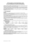
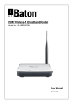
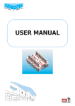
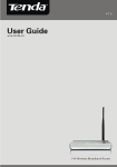
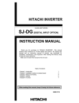
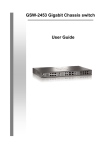
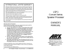
USER MANUAL
pickering
Model No. 10-920A/10-921
(CONCISE VERSION)
IEEE-488.2/RS-232 Interface Module
IEEE-488.2
RS
232
Designed & Manufactured by:Pickering Interfaces Limited.
Stephenson Road
Clacton-on-Sea
Essex
CO15 4NL
England
Tel:
Fax:
+44 1255-428141
+44 1255-475058
01255-428141 (UK)
01255-475058 (UK)
Internet: www.pickeringswitch.com
E Mail: [email protected]
Issue 2.02 June 1997
© Copyright (1997) Pickering Interfaces Ltd. All Rights Reserved
pickering
10-921 (Concise Version)
IEEE-488.2/RS-232 Interface Module
1
HELP!!!
If you need assistance with your Pickering Interfaces Switching
System: Switching problems, Programming or Integration within your Test
System. – Please ring Pickering Interfaces and ask for “Technical
Support”.
Alternatively you may fax, email or connect to our Internet Web Site.
A full set of operating manuals, application notes and software drivers is
available on CD ROM.
pickering
2
10-921(Concise Version)
IEEE-488.2/RS-232 Interface Module
Contents
Section 1
The Intelligent GPIB/RS-232 Interface: Introduction ................................................ 5
Section 2
Getting Started: Setting Up and Testing Your System ............................................... 7
Section 3
IEEE-488.2/RS-232 Programming of System 10/20.................................................. 9
Section 4
System 10/20 Commands ....................................................................................... 13
Section 5
IEEE- 488.2 Command Summary ........................................................................... 19
Section 6
Common Problems & Troubleshooting .................................................................... 23
Section 7
IEEE-488.1 Interface Functions ............................................................................... 25
Section 8
RS-232 Interface Details.......................................................................................... 27
Appendix A
Self-Test Failure Table .............................................................................................
Appendix B
Error Message Table ................................................................................................
Appendix D
IEEE-488.2 Status Registers ...................................................................................
Appendix E
Command Execution Times .....................................................................................
Appendix F
Electrical, Environmental & Mechanical...................................................................
pickering
31
33
35
37
41
10-921 (Concise Version)
IEEE-488.2/RS-232 Interface Module
3
10-921 IEEE-488.2/RS-232 Interface Module Uses a 32 Bit Microprocessor (68332) For Increased
Throughput.
(All Code is stored in Flash ROM allowing easy future upgrades)
pickering
4
10-921(Concise Version)
IEEE-488.2/RS-232 Interface Module
Section 1
The Intelligent GPIB/RS-232 Interface: Introduction
1.1 Model 10-921 Features
•
Fully IEEE-488.1 Compatible. Adheres to IEEE-488.2 (1988) Standard “Codes, Formats, Protocols and Common
Commands”, thus providing a familiar software interface.
•
GPIB Talker/Listener with Service Request & Device Clear.
•
RS-232 Interface 1200 to 56k baud with software or hardware handshaking
•
Extensive error handling and reporting in English language or numeric format.
•
Comprehensive and easy to use instruction set.
•
Supports ALL System 10/20 Modules and Configurations
•
Internal flash memory allows easy updates from Disc or Internet
•
Large input and output buffers increase GPIB/RS-232 through-put.
•
Stored settings registers (up to 100) enable quick recall of previous switch configurations.
•
Supports all Pickering Switching Modules.
•
32 Bit Microprocessor For Fast Response
•
Controls over 30 Internal Switching Modules (many more using expansion modules).
•
Full Self Test Diagnosis Support
The 10-921 RS-232-C/IEEE-488.2 Interface Module provides a versatile means of communicating with a Pickering
Interfaces’ Switching System. The instruction set has been designed to ease integration of System 10/20 into your Test
or Data Acquisition environment. This includes complete error and status reporting as defined in IEEE-488.2 which
enables service request (SRQ) to be sent on the occurrence of several programmable “standard” events. The use of a
32 bit microprocessor ensures maximum response and throughput.
1.1.2 Fast and Easy Programming
The 10-921 uses a 32 bit microprocessor (Motorola 68332) to give maximum operating throughput. All programming is
done in ASCII using English-like instructions with support for most number formats, all instructions follow exactly the same
syntax. Incoming instructions are placed into an input buffer, therefore a large block of instructions may be sent to the
interface which can then be left to execute, thus leaving the control computer free to carry out other tasks. A large output
buffer simplifies status and error reporting.
Full support is given to application program debug using the VIEW? and REPORT? instructions, any incoming instruction
which causes offence (due to incorrect or invalid instructions or arguments) can be read back together with a description
of the problem. In addition self testing and detailed fault diagnosis simplify test system debug and maintenance.
The 10-921 interface module provides any System 10/20 Switching System with a full RS-232-C and IEEE-488.2
interface. The 10-921 interface features powerful but easy to use instructions, which hide many of the intricacies required
when operating complex switching systems, especially large multiplexers (scanners) and matrices.
1.1.3 IEEE-488.2 Compatible
The 10-921 Intelligent Interface is totally compatible with the IEEE-488.2 (1987) standard, both the IEEE-488 and RS232-C interfaces follow IEEE-488.2 Protocols.
This software standard is the basis for SCPI and is much used in VXI based instrumentation. For further information on
the IEEE-488.2 standard please refer to chapter 5.
RS-232-C: The serial interface allows System 10 and 20 units to be controlled from any standard PC, with a wide range
of baud rates plus a choice of software or hardware handshaking.
IEEE-488 (GPIB): High speed IEEE-488.2 interface. The 10-921 is a faster version of the 10-920 interface module, the
two modules are compatible.
Both the IEEE-488 and RS-232 interfaces can be run simultaneously. This is frequently used when the IEEE-488
interface is used for programmed control while the RS-232 interface is used for occasional status reporting to a serial
terminal or printer.
1.1.4 Additional Self Test Support
The 10-921 Intelligent Interface has a recessed self test button, “MAN TEST”. If this button is pressed a full switching self
test will occur, if an error was found the “ERR” LED will go on, use the DIAGNOSTIC? command to find the cause. Also
if the self test button is held in for approximately 5 seconds the unit goes into a system exercising mode (which can only
be stopped by holding down this button again), this will continually exercise all the relays and then run self test. Detailed
self test results can then be viewed using the DIAGNOSTIC? 1 query.
pickering
10-921 (Concise Version)
IEEE-488.2/RS-232 Interface Module
5
1.2 Switching System Control
System 10/20 switching modules are easily programmed using the OPEN, CLOSE, WRITE, CHAN, MCLOSE and
MOPEN commands listed in section 4.1. Switches may be controlled either individually or as words (8, 16 or 32 bit).
Examples:
O PEN 12 , 4
open switch
command
address 12
WRITE 16 , 170
send word
command
switch 4
CHAN 22 , 67
scanner: channel
select command
address 16 bit pattern
10101010
MCLO SE 7 , 3 , 2
address 22
close
channel 67
open matrix
cross-point
command
y=2
address 7
x=3
Fig 1.1 Example Instructions
(also supports other IEEE-488.2 number formats)
1.3 IEEE-488.2 (1987)
The Intelligent GPIB Interface has been designed to conform to the IEEE-488.2 Standard “Codes, Formats, Protocols and
Common Commands”, this carries with it many future benefits. But anyone using System 10/20 can, if they desire, ignore
all “standard” commands and just use specific System 10/20 commands with no loss of switch control.
IEEE-488.2 is completely compatible with the original IEEE-488 (1978) standard. It has been designed to sit on top of
IEEE-488.1 as a second layer. IEEE-488.1 defined a complete mechanical, electrical and data exchange standard.
However it stopped short of defining any message exchange protocol, data structures or status reporting. So each
equipment manufacturer used their own formats. IEEE-488.2 defines a message exchange protocol with error handling,
status reporting, defined data structures and a mandatory and optional command set.
Its main objective has been to present a standard software interface to the applications programmer. This will greatly
reduce the time spent becoming familiar with a new instrument, for once learnt, each new instrument will have the same
standard interface. Only the device specific functions will have to be learnt.
1.5 Powering Up With System 20 Modules
The more recent System 20 range of switching modules (particularly high density matrix) have extensive built-in self test
facilities. Because of this self testing the power-on period may take up to 1 minute instead of the 15 seconds for System
10/20 only units, please refer to Sec 2.1 for further details.
1.6 How To Use This Manual
Section 2 explains how to install the Intelligent GPIB Interface. Read through all Section 3 “Programming System 10/20”
(this deals with the way instructions and data are processed). Sections 4 and 5 list all programming instructions, while
Section 6 helps you through many of the problems that you may encounter.
Finally if you need some information which is not given in this manual please don't hesitate to call us, we should be able
to help you.
10-921-001 RS-232-C/IEEE-488.2 Interface
10-952-020 Serial Connection Cable, 25 Way, 2m length, plugs directly into PC
10-952-120 Serial Connection Cable, 9 Way, 2m length, plugs directly into PC
Table 1.1 Order Codes
pickering
6
10-921(Concise Version)
IEEE-488.2/RS-232 Interface Module
Section 2
Getting Started: Setting Up and Testing Your System
2.1 Installation
All switching systems are usually shipped from the factory pre-configured, and are despatched with
a “System Schematic Diagram”, this describes the type, location and address of all switching
modules. So most of the installation instructions given in this and the Ancillaries manual (10-910/930)
will in most cases not be required.
The 10-921 interface is factory configured as follows:
• IEEE-488 address = 10
• RS-232 configuration = 9600 baud, hardware handshake, 8 bit word with 1 stop bit and no parity.
The IEEE-488 addressing and RS-232 configurations are set via software commands (no DIP switches), to change these
settings use the CONFIG command (see section 4).
Note: If any switching module has extended self test functions (e.g. System 20 matrix modules) then the 10-921 may take
up to 1 minute to startup, this again is controlled bythe CONFIG command (see section 4).
2.1 Testing
In order for the GPIB/RS-232 Interface to work correctly there must be at least one switching module present in the rack.
Now turn on the power, check to see that the “ACTIVE” & “ERROR” LEDs flash. If “ERROR” stays on it is usually because
there are no switching modules present in the backplane.
If everything is OK both LEDs will go off. Now attach the IEEE-488 or RS-232 connector directly from your computer to
the 10-921 Interface (make sure no other devices are on the IEEE-488 bus at this stage).
To test out System 10/20, first send the command “REPORT?”, if the Interface is happy then you should receive the
message “OK.”. The “IEEE-488” or “RS-232” LED will indicate which port is active.
Now try the following query instructions:VIEW?tells you what is in the System 10/20 rack.
*IDN? gives information about the Interface Model.
*TST? performs a self-test (watch the LEDs flash), this should return 0.
2.2 Problems
If you cannot get the 10-921 Interface to respond, your controller software may not be set up correctly, refer to Section
3.2 for a description of the message exchange protocol. If this does not solve the problem then see Section 6 or contact
Pickering for further advice.
“POWER” LED (red) indicates when the 5V power supply is on.
“ACTIVE” LED (green) indicates when the interface is working (receiving, transmitting or executing commands).
“TEST” LED (yellow) is set when the system is running a self test.
“ERR” LED (red) is set whenever a “System Error” occurs (use
REPORT? to find the cause), this will only be cleared when the
machine is switched off.
“GPIB” LED (green) is set when the IEEE-488 bus is controlling the
switching system.
“RS232” LED (green) is set when the RS-232 bus is controlling the
switching system.
Fig 2.1 Front Panel Display LEDs
pickering
10-921 (Concise Version)
IEEE-488.2/RS-232 Interface Module
7
pickering
8
10-921(Concise Version)
IEEE-488.2/RS-232 Interface Module
Section 3
IEEE-488.2/RS-232 Programming of System 10/20
3.1 System 10/20 Programming
The IEEE-488.2/RS-232 Interface can be programmed on two different levels:
Level 1.
Suitable for learning and driving simple switching systems. Uses only those commands listed in section 4
“System 10/20 Commands”. Experiment with some of the examples shown in section 4.6.
Level 2.
Is used in systems which are complex and time sensitive (e.g. Automatic Test Equipment). Uses the
commands listed in both section 4 and in section 5 “IEEE-488.2 Command Summary”.
Once you have tested and established communication with the Intelligent GPIB Interface you should start programming
using just Level 1 instructions.
RS-232 Note: The following description discuss the IEEE-488 interface bus, all RS-232 commands
behave in a similar way (except those commands which are hardware dependent, e.g. SRQ).
3.1.1 Instruction Processing
A brief understanding of the Intelligent GPIB Interfaces’ handling of instructions is necessary. All incoming instructions
are stored in an input buffer (> 250 bytes), see fig 3.1, which holds the data until the Parser is ready to look at it. If the
instruction is OK it is passed directly to the Execution Unit where it will be run.
If any error occurs along this path the error will be immediately reported in the Standard Event Status Register (fig 5.1),
this register can be programmed to send an SRQ to the controller. See appendix D for details of status registers.
All return messages or queries are stored in an output buffer (> 250 bytes), this is used to store the message until the
controller requests it. The presence of a message in the output buffer is indicated by the MAV bit in the Status Byte
Register.
Number Formats: System 10/20 uses only integer numbers, however if a number is supplied in a non-integer format it
will always be rounded to the nearest integer value. For example 1, 1.3789, 0.89 or 100.789x10⁻² will all be read as the
integer 1.
3.2 System 10/20 Message Exchange Protocol
3.2.1 Program Message Structure
The following description uses a simplified version of the terminology employed in the IEEE-488.2 Standard, to which
System 10/20 conforms. If a full and rigorous description is required the user should refer to that standard.
The basic element used in programming System 10/20 is the program instruction. A program instruction consists of
a sequence of data bytes sent to System 10/20 which form a command which is recognised by System 10/20. e.g. “WRITE
1,5”.
A program message consists of a sequence of program instructions. All programming of System 10/20 should be
performed using complete program messages. The program message must be terminated either:
a) by a newline data byte (ASCII character 10 decimal)
b) by a IEEE 488.1 <EOI> sent with the last data byte
or
c) by both of these together.
A program message may contain a number of program instructions. Individual program instructions within a program
message are separated by the semicolon ‘;’ (ASCII character 59 decimal), e.g. “WRITE 1,5;WRITE 1,6”.
3.2.2 Program Instruction Types
A program instruction may be either a command instruction, which does not cause System 10/20 to return any data to
the controller, or a query instruction, which does cause it to do so. Query instructions are distinguished by a query mark
‘?’ (ASCII character 63 decimal) as the final character of their mnemonic. The two types of program instruction are reflected
in two forms of program message:
Command Message.
pickering
A command message contains no query instructions, and does not cause System 10/20
to return any data to the controller. Such messages may be sent without restriction, e.g.
“*RST;*CLS;*SRE 32”.
10-921 (Concise Version)
IEEE-488.2/RS-232 Interface Module
9
Query Message.
A query message contains one or more query instructions, and causes System 10/20 to
generate data for return to the controller. System 10/20 expects such messages to be
handled on a ‘one - for - one’ basis, i.e. the controller should issue a query message and
then read the System 10/20 response to that message before sending System 10/20 any
further instructions. An error will be detected if this protocol is violated (RESPONSE
INTERRUPTED). Any attempt to read data from System 10/20 without having previously
issued a valid query message will also cause an error (UNTERMINATED MESSAGE).
3.2.3 Response Messages
System 10/20 returns data to the controller in the form of a response message . A response message consists of a
sequence of bytes, terminated by a response terminator which is defined as a newline data byte (ASCII character 10
decimal) sent with IEEE 488.1 <EOI>.
Similar to the program message, a response message may contain a number of response units, such units again being
separated by the semicolon ‘;’ (ASCII character 59 decimal).
In general, a program message may contain any combination of command instruction and query instruction elements.
Where more than one query instruction is present in the program message, the message is a compound query. The
response to each query instruction will be included in the response message in the order in which the query instructions
were present in the program message, separated by semicolons. However, certain query instructions produce a response
in a form the end of which can only be unambiguously determined by the response terminator defined above. These
queries cannot have further queries compounded after them, and System 10/20 will detect an error (ILLEGAL
COMPOUND QUERY) if such an operation is attempted, e.g. “VIEW?;*IDN?”.
IEEE-488.1 BUS
C ONTROL
DATA
I/O C ONTROL
OUTPUT
QUEUE
(512 BYTES)
INPUT
BUFFER
(256 BYTES)
PARSER
QUERY
ERROR
(QYE)
MESSAGE
EXC HANGE
C ONTROL
EXEC UTION
UNIT
DEVIC E FUNC TIONS
DEVIC E DEPENDENT
ERROR
(DDE)
POW ER
ON
(PON)
OPERATION
C OMPLETE
(OPC )
Fig 3.1 Block Diagram of Instruction Processing
pickering
10
C OMMAND
ERROR
(C ME)
10-921(Concise Version)
IEEE-488.2/RS-232 Interface Module
EXEC UTION
ERROR
(EXE)
3.2.4 Buffer Overflows
Should System 10/20 be asked to buffer more data than it is able, because the controller sends an extensive query
message which fills the System 10/20 output buffer with response data, and continues sending until the input buffer is
also full, an error is detected (BUFFERS DEADLOCKED).
The buffer sizes provided (> 250 bytes) are sufficient to make the occurrence of this condition unlikely in normal operation.
3.2.5 Error handling
All the above errors in protocol result in a IEEE-488.2 query error. System 10/20 recovers from these errors as follows:
RESPONSE INTERRUPTED
The contents of the output buffer are discarded, and System 10/20 resumes reading
from its input buffer.
UNTERMINATED MESSAGE
The contents of the output buffer are discarded, and System 10/20 awaits a new
program message.
ILLEGAL COMPOUND QUERY
Any further query instructions in the current message are discarded. When the end
of the query message is found, System 10/20 generates its response terminator as
usual and normal operation is restored.
BUFFERS DEADLOCKED
The contents of the output buffer are discarded, and System 10/20 resumes reading
from its input buffer. Any query instructions encountered are discarded. Normal
operation is restored when the end of the query message is found.
3.3 Switching Times
When programming System 10/20 always bear in mind the inherent delay all mechanical switches carry - however most
switching commands take around 15mS, so this should not usually be a problem. But particular note should be made
of power up/down situations.
Power On: All modules are cleared (i.e. all relays opened and all digital outputs set high); all stored settings (*SAV/
*RCL registers) are cleared. PON bit in the Event Status Register (bit 7) is set.
Power Off: RESET (or *RST) command must be issued to clear all relay modules prior to power being removed otherwise
the power down sequence is unpredictable.
Note: the average physical release times of different modules will vary considerably:–
Transistor output
< 1µS
Dry Form A Reed Relay
0.5mS
Dry Form C Reed Relay
1mS
Mercury Wetted Form A Reed Relay
2mS
Mercury Wetted Form C Reed Relay
3mS
High Voltage Reed Relays
5mS
Power Relays
10mS
R.F. Relays
10-20mS
3.4 Further Notes
All device specific instructions may be abbreviated to 2 or 3 characters, e.g. RE for RESET, VI? for VIEW?, they may
be any combination of UPPER or lower case characters - however all response messages will be in UPPER case.
All System 10/20 commands are compatible with IEEE-488 (1978) and IEEE-488.2 (1988) - for details of IEEE-488.2
Instructions refer to the standard, obtainable from IEEE Services Center, 445 Hoes Lane, Piscataway, NJ 08854, U.S.A
(tel. 010.1.201.981.0060) or from Pickering.
pickering
10-921 (Concise Version)
IEEE-488.2/RS-232 Interface Module
11
pickering
12
10-921(Concise Version)
IEEE-488.2/RS-232 Interface Module
*CLS
m
*ESE *ESE? *ESR?
m
*SRE *SRE? *STB?
Status Reporting
CHAN a,c
CHAN a,b,c
CHAN a,b,c,e
y
x,
b,
a,
MOPEN a,x,y
MOPEN a,b,x,y
y
x,
b,
a,
MCLOSE MOPEN
Matrix
DELAY t
t
DELAY
Time
VIEW?
VIEW? a
VIEW? a,b
VIEW? a,b,c
n
b,
a,
VIEW?
*IDN?
*RST
r
*RCL
r
*SAV
Stored Settings
*OPC *OPC?
*DMC
*GMC? *LMC? *PMC
Macros
m
Future Enhancements
*EMC *EMC
m
delay
hand,
baud,
address,
BOOT
*LRN?
Learn
CONFIG CONFIG?
Configuration
CONFIG address
CONFIG address, baud
CONFIG address, baud, hand
CONFIG address, baud, hand, delay
example:
CONFIG 10 (set GPIB address to 10)
CONFIG 10,5,1,40 (set GPIB, RS-232
to 9600 hardware handshake with 40S
startup delay)
SIZE a
a
SIZE SIZE?
Fig 3.2 Instruction Set Tree
*WAI
Synchronisation
Example
*SAV 3 (save switching system
status to register 3)
*RCL 2 (recall register 2)
Register 0 will be automatically
loaded at power up.
*TST?
Internal Operations
TYPE?
TYPE? a
TYPE? a,b
b
a,
TYPE?
Status
10-921 IEEE-488.2/RS-232 Instruction Set
(send word to
module 5)
c,
READ? a
READ? a,n
w
e
b,
a,
CHAN
Multiplexer
n
a,
READ?
Digital Input
b,
a,
WRITE
WRITE a,w
WRITE a,b,w
example:
WRITE 5,65264
n
a,
OPEN
CLOSE a,n
example:
CLOSE 5,9 (close relay 9
on module 5)
n
b
examples:
ARESET 8 (clear module 8)
ARESET 8,3 (clear module 8
bank 3)
ARESET a
ARESET a,b
a,
CLOSE
Switch/Digital Output
a,
RESET ARESET
Clear
10-921 System 10/20 Updated Instruction Set
November 1995
Shaded Areas show allowed
instruction parameter combinations
together with examples
=
=
=
=
=
=
=
=
=
=
=
DIAGNOSTIC?
DIAGNOSTIC? a
a
REPORT? ERRNO? DIAGNOSTIC?
module address
bank number
channel number
multiplexer channel enable
byte mask
bit number
recall register
size
time delay in mS
matrix x coordinate
matrix y coordinate
Examples of Input Numbers:
Decimal 170 (no prefix)
Binary #B10101010
Hex
#HAA
Octal
#Q252
Key:
a
b
c
e
m
n
r
s
t
x
y
BASE?
Examples of Output Numbers:
BASE 4 (set output number
base to hex)
BASE 3 (set output number
base to decimal)
BASE? (query current base
output number)
number
BASE
Errors
Section 4
System 10/20 Commands
4.1 Commands
RESET
Reset Command. Clear all modules to inactive state (as at power on).
ARESET a
Addressed Reset Command. Clear module a (as at power on).
ARESET 3 to clear module at address 3.
CLOSE a , b
Switch Close Command. Close switch b on module a.
CLOSE 3,4 will close switch number 4 on the module with address 3.
OPEN a , b
Switch Open Command. Open switch b on module a.
WRITE a , w
Switch Write Command. Write word w to module a.
WRITE 4,65 will set the 8 bits on module 4 to the bit pattern 01000001.
WRITE 5,65535 will set all bits on module 5 (16 bit unit).
WRITE 205,255 will set all bits on module 5 bank 2 (i.e. bits 9-16).
READ? a
Digital Input Read Word Query. Read input word from module a.
READ 5 will read all input bits on module 5.
READ 205 will read the byte on module 5 bank 2 (i.e. bits 9-16).
NB. If the bit number b, is included as a second argument,
i.e. READ a , b then a “1” (5V) or “0” (0V) will be returned.
READ? a , b
Digital Input Read Bit Query. Read input bit from module a.
READ 5,3 will read state of input bit number 3 on module 5. Returned value: “1” (5V) or “0” (0V).
CHAN a , c
Standard Multiplexer Command. Close channel c on multiplexer a, with break-before-make
action (only one channel at a time may be selected).
CHAN 23,6 closes channel number 6 (all other channels open) on module address 23.
CHAN 208,6 closes channel number 6 (all other channels open) on bank 2 of module address 8.
CHAN a , c , e
Multi-Channel Multiplexer Command. Operate channel c on multiplexer a: Set channel if e = 1,
Clear channel if e = 0.
CHAN 23,2,1 closes channel number 2 on module address 23 (all other channels unaffected).
CHAN 23,2,0 opens channel number 2 (all other channels unaffected).
MCLOSE a , x , y
MOPEN a , x , y
DELAY t
[Future Feature: If e = 9 all channels except the one specified will be closed, e.g. CHAN 23,7,9 will
close all channels at address 23 except channel 7 (note all channels are first cleared before all but
channel 7 are set). This is intended for isolation testing applications, great care must be taken
when using this function, be sure not to over-rate the power supply when using a large multiplexer
composed of several modules].
Close Matrix Crosspoint Command. Close switch at coordinates x, y on module a.
MCLOSE 25,3,5 Close switch at coordinates 3,5 on module with address 25.
Open Matrix Crosspoint Command. Open switch at coordinates x, y on module a.
Delay Command. Delay of t milliseconds.
DELAY 70 sets a delay of 70 milliseconds. This could be used to force a minimum delay between
two events.
e.g. WRITE 1,4;DELAY 70; WRITE 1,8
NB. When using DELAY bear in mind the execution time of other commands (see Appendix E).
4.2 Status Queries
TYPE? a
Return type and size of module a.
Return Values:
“OUTPUT”
“DIGITAL”
“MUX”
“MUXM”
“MATRIX”
“UNDEFINED”
“ABSENT”
pickering
Uncommitted Relay or Digital Output
Digital Input/Output
Multiplexer (Single Channel)
Multiplexer (Multiple Channel)
Matrix
Device Type Unknown
No Device at that Address
10-921 (Concise Version)
IEEE-488.2/RS-232 Interface Module
13
The size of the module is indicated by the value in round brackets appended to the type, e.g.
MATRIX(8x8). Some multiplexers have two banks, e.g. MUXM(2x8) is a multi-channel dual
multiplexer, each bank having 8 channel capacity.
If there is a suspected problem then a “-?” will be added, e.g. “OUTPUT(8) -?”
Response message format (IEEE-488.2): <Arbitrary ASCII Response Data>.
VIEW? a , b
Return current setting of switch b on module a (which must be a latch or digital output module).
Return values:“1”
“0”
Switch closed. Transistor on. TTL output at 5V.
Switch open. Transistor off. TTL output at 0V.
Response message format (IEEE-488.2): <NR1>.
VIEW? a , c
Return current setting of channel c on multiplexer a (which must be a multiplexer module).
Return values:“1”
“0”
Channel closed.
Channel open.
Response message format (IEEE-488.2): <NR1>.
VIEW? a , x, y
Return current setting of crosspoint at coordinates x, y on matrix a (which must be a matrix module).
Return values:“1”
“0”
Crosspoint selected.
Crosspoint open.
Response message format (IEEE-488.2): <NR1>.
VIEW? a
Return current switch state of module a.
Return values:
8 Bit Latch
“0” to “ 255”.
Digital Output
“0” to “ 65535”.
Multiplexer
“0” to “c” Off state = 0.
Matrix
[“0” to “x”,”0" to “y”] Off state = [0,0].
Response message format (IEEE-488.2): <Arbitrary ASCII Response Data>.
VIEW? 10 for a matrix will return “[2,7]”, i.e. matrix coordinates are: x = 2, y = 7. Multiple cross-points
will be in a list form e.g. “[2,7][3,6][4,1][9,7]”.
VIEW?
Return current type and switch state of all modules.
Response message format (IEEE-488.2): <Arbitrary ASCII Response Data>.
A typical return string might be: “SYSTEM 10 STATUS; OUTPUT(8) 2,255;MATRIX(8x8)
3,[2,7][3,6][4,1];MUX(32) 14,25;MUXM(56) 15,1,2,4;2,3,8,34”.
NB: The VIEW? command will not read digital input, the READ? command must be used to do this.
4.3 Configuration Commands
SIZE
Defines the length of a word arguments, w. This is used when writing or reading words to a digital
i/o or general purpose relay module. The size is held in non-volatile. Word length may be set as
follows:
8 bit word (byte)
16 bit word
32 bit word
SIZE?
Returns a string describing the current word size. Returned values are:BYTE
WORD
LONG
BASE
SIZE 1
SIZE 2
SIZE 3
8 bit word
16 bit word
32 bit word
Defines the number base being used (the number base convention is as used in the IEEE-488.2
standard).
of a word arguments, w. This is used when writing or reading words to a digital i/o or general purpose
relay module. The number base is held in non-volatile, it may be set as follows:
Binary
Octal
Decimal
Hexadecimal
BASE?
BASE
BASE
BASE
BASE
1
2
3
4
Returns a error string describing the last error to occur. When REPORT? is used the error string is
always cleared to “OK.”
Response message format (IEEE-488.2): <Arbitrary ASCII Response Data>.
pickering
14
10-921(Concise Version)
IEEE-488.2/RS-232 Interface Module
CONFIG
Defines the IEEE-488 and RS-232 configuration and addressing, see Fig 4.1
CONFIG address, baud, hand, delay
GPIB Address
(in range 0 to 30,
factory default = 10)
RS-232 Baud Rate:
1 = 300 baud
Handshake
2 = 1200 baud
1 = Hardware Handshake
3 = 2400 baud
0 = Software Handshake
4 = 4800 baud
(XON/XOFF)
5 = 9600 baud (factory default)
6 = 19200 baud
7 = 38400 baud
8 = 57600 baud
Startup Delay (in
Seconds). This is
usually factory set to
match the switching
modules in the
system.
Fig 4.1 The CONFIG Command
CONFIG?
Returns a error string describing the current configuration.
Response message format (IEEE-488.2): <Arbitrary ASCII Response Data>.
4.4 Error Queries
REPORT?
Returns a error string describing the last error to occur. When REPORT? is used the error string is
always cleared to “OK.”
Response message format (IEEE-488.2): <Arbitrary ASCII Response Data>.
If the instruction “WRITE 10,4” is sent and does not work then the error message: “WRITE 10,4; <FAILED TO EXECUTE,ADDRESS 4.” is returned.
A full list of all error messages is included in Appendix B “Error Message Table”.
ERRNO?
Returns an error value in range “0” - “255”, each error number corresponds directly to an error string
returned by REPORT?. When ERRNO? is used the error number is cleared to “0”.
For details of error numbers refer to Appendix B “Error Message Table”.
Response message format (IEEE-488.2): <NR1 Numeric Response Data>.
DIAGNOSTIC?
Returns a diagnostic error report string.
Note: For large systems this string may be quite large, up to 1000bytes.
Note: The diagnostic string does not have a fixed format, so it should NOT be deconstructed by
software. It is intended to be read directly by a maintenance engineer.
Response message format (IEEE-488.2): <Arbitrary ASCII Response Data>.
DIAGNOSTIC? 1
Returns a detailed configuration and diagnostic error report string.
4.4 Argument Definitions
a = 0 - 30
Note: Digital I/O and Dual 8 to 1 Multiplexer modules may also be addressed by bank numbers - this is
very useful when your programme will not handle unsigned 16 bit integers.
Word
w = 0 - 65535.
Bit
b = 1 - 64.
Channel
c = 1 - (Last channel number)
Coordinates
x = 1 - (Last x coordinate)
y = 1 - (Last y coordinate)
Time
t = 0 - 599999 (i.e. 1 millisecond to 10 minutes)
Address
pickering
10-921 (Concise Version)
IEEE-488.2/RS-232 Interface Module
15
4.5 Module Types
All modules may have an address from 0 to 30 - Address 31 is illegal -.
Latch
Switches 1 - 64 may be written to.
Digital I/O
Outputs 1 - 16 or 32 may be written to. To input data use READ.
Multiplexer
Each multiplexer address may currently contain up to 1024 channels, Channel 1 must always be used, if
not then erroneous results will occur.
Matrix
Each matrix address may currently contain from 32 to over 15360 cross points. Cross-point x =1, y = 1
must always be used, if not then erroneous results will occur.
Logic Levels
Switch/Output Type
Logical ‘1’
Logical ‘0’
Relay
On
Off
TTL Input/Output
5V
0V
Open Collector Transistor
On
Off
A logical ‘1’ sent to a relay will always turn the switch on and a ‘0’ will turn it off.
B1
A1
C1
B5
A5
C5
B2
A2
C2
B6
A6
C6
B3
A3
C3
B7
A7
C7
B4
A4
C4
B8
A8
C8
Fig 4.2 Uncommitted Relay Schematic (Latch type)
Isolation
Switch
Y1 Y2 Y3 Y4 Y5 Y6 Y7 Y8
X1
X2
X3
X4
X5
X6
X8
X 19
Matrix
Crosspoint
X7
X 20
Fig 4.3 Switching Matrix Schematic
pickering
16
10-921(Concise Version)
IEEE-488.2/RS-232 Interface Module
Any combination of crosspoints may be selected (except on RF matrix module type 20-750, where only one crosspoint
per row or column may be operated).
1.1
Bank 1
1.2
2.1
2.2
1.2
2.1
Common
1.1
28.1
28.2
Bank 2
C.1
1.1
1.2
C.2
16.1
2.1
16.2
2.2
Common
Common
2.2
28.1
28.2
Fig 4.4 Multiplexer Schematics
(Single 16 Channel Multiplexer Left, Dual 28 Channel Multiplexer Right)
Multiplexers can be operated in either single channel mode (break-before-make) or in multi channel mode (any
combination of channels selected).
4.6 Simple Programming Examples
Use the programming examples below to get you started.
8 bit latch at address 11.
To turn on then off all 8 switches
WRITE 11,255;WRITE 11,0 or
To turn off then on switch 5
OPEN 11,5;CLOSE 11,5
To look at bit 5
VIEW? 11,5 will return “1”.
To look at address 11
VIEW? 11 will return “16”.
WRITE 11,255;ARESET 11
16 bit Output at address 27.
To turn on then off switch 10
CLOSE 27,10;OPEN 27,10
To turn on all 16 switches
WRITE 27,65535 or
To look at address 27
VIEW? 27 will return “65535”.
WRITE 127,255;WRITE 227,255
16 bit Input at address 27.
To read 16 bit word
READ 27 will return number in range 0-65535
To read 8 bit byte (in bank 2)
READ 227 will return number in range 0-255
Multiplexer at address 0.
To turn on channels 1, 3, 8
CHAN 0,1;CHAN 0,3;CHAN 0,8
Note: a make-before-break is automatically enforced.
To clear the multiplexer (no channels on)
ARESET 0
Matrix at address 19.
To turn on crosspoint x = 2, y = 4
MCLOSE 19,2,4
Turn off previous setting and turn on crosspoints at x = 3, y = 7 and x = 4, y = 7
MOPEN 19,2,4;MCLOSE 19,3,7;MCLOSE 19,4,7
To clear the whole matrix
ARESET 19
Error reporting.
pickering
10-921 (Concise Version)
IEEE-488.2/RS-232 Interface Module
17
Writing data to non existent latch
WRITE 10,56;REPORT?
“WRITE 10,56<10> <- DEVICE ABSENT.” is returned.
Writing data to wrong device type
WRITE 8,255;REPORT?
“WRITE 8,255<10> <- INCOMPATIBLE INSTRUCTION.” is returned if the device at address 8 is a matrix.
The ERRNO? query may be used after every instruction to check the result. For instance when operating an 8
bit latch at address 29:WRITE 29,255;ERRNO? returns “0”. But
WRITE 29,65000;ERRNO? returns “16”. - See Appendix B for error description.
4.7 Software Limitations
Due to RAM limitations within the 10-920 module (currently 8k bytes) the following module types have preset size limits,
these limitations do not apply to the more recent 10-921 module (which has 64kRAM):Matrix
Maximum number of crosspoints per compound matrix: 50
Maximum number of compound matrices per system:
12
Multiplexer
Maximum number of channels per compound multiplexer:
1024
Maximum number of compound multiplexers per system:10
(this counts a dual multiplexer as 2, i.e. max of 5 dual multiplexers)
If any of the above limitations may cause a problem please contact sales office, an updated EPROM configured to your
requirements can be provided.
pickering
18
10-921(Concise Version)
IEEE-488.2/RS-232 Interface Module
Section 5
IEEE- 488.2 Command Summary
For a detailed description of IEEE-488.2 commands, status bytes and data structures refer to the standard (available
from Pickering).
5.1 Status Reporting
*CLS
Clear Status Command. Clears the Event Status Register & MAV bit in the Status Byte
*ESE m
Sets the selected bits in the Standard Event Status Enable Register.
*ESE?
Event Status Enable Query.
Returns: “0” - “255”.
*ESR?
Event Status Register Query.
Returns: “0” - “255”.
*SRE m
Sets the selected bits in the Service Request Enable Register.
*SRE?
Status Register Enable Query.
Returns: “0” - “63” or “128” - “191”.
*STB?
Status Byte Query.
Returns: “0” - “255”.
Mask m = 0 - 255.
Figure 5.1 illustrates the two status registers, for further details refer to Appendix D.
5.2 Synchronisation
*OPC
Operation Complete Command. Sets the OPC bit in Event Status Register when all pending commands
have completed.
*OPC?
Operation Complete Query. Places a “1” in the o/p queue when all pending commands have completed.
*WAI
Wait-to-Continue Command
Stop any further commands from being executed until all previous commands are complete.
5.3 Stored Settings (*SAV/*RCL)
There are 255 internal memories which are available for storing the current state of all switching modules. These
memories can later be recalled to load a previously stored configuration. This feature is very useful when complex
configuration changes have to be made frequently.
These memory blocks are cleared by the *RST command or upon power up.
*RCL r
Restore the state of all modules to that stored in memory r .
*SAV r
Save the current state of all modules to memory r.
Register r
0 - 255 (memory permitting).
Register 0 will automatically load at power up.
Note:
The *RCL & *SAV commands only affect internal modules, all other data structures are unaffected.
The *RCL sequence will be by address (i.e. address 0, 1, 2 ....), so beware of potentially unpredictable
switch combinations!
pickering
10-921 (Concise Version)
IEEE-488.2/RS-232 Interface Module
19
Q uery Error
DDE
3
QYE RQC
2
1
O p eration Comp lete
Device Dep endent Error
EXE
4
Request Control
Execution Error
Command Error
User Request
Power O N
PON URQ CME
7
6
5
OPC
0
Standard Event Status Register
(* ESR?)
&
&
Logical O R
&
&
&
&
&
&
7
6
EXE
4
DDE
3
QYE RQC
2
1
OPC
0
Message Availab le
RQ S
CME
5
Event status B it
PON URQ
7
6
ESR MAV
5
4
Standard Event Status Enab le
(* ESE m, * ESE?)
Read b y Serial Poll
3
2
1
0
Status Byte Register
Read b y *STB ?
MSS
&
Logical O R
&
&
&
&
&
&
7
ESB MAV
5
4
3
2
1
0
Service Request Enab le Enab le
(* SRE m, * SRE?)
For details of status register bit functions refer to Appendix D.
Fig 5.1 IEEE-488.2 Status Reporting
pickering
20
10-921(Concise Version)
IEEE-488.2/RS-232 Interface Module
5.4 Internal Operations
*IDN?
Identification Query.
*TST?
Self Test Query. This will run a check of all testable components on the circuit board including flashing the
“ACTIVE” and “ERROR” LEDs. If a non–zero value returned then the test failed. The value returned indicates
the problem, see Self-Test Failure Table. This will enforce a self-test on all matrix, multiplexer, uncommitted
relay and digital I/O modules which have a built in micro-controller. Self Test may take up to 1 minute when
using System 20 high density matrix modules (you may therefore need to adjust your read time out, many
programs typically time out after just 10 seconds!).
Returns an identification string.
If a non-zero value is returned use DIAGNOSTIC? to indicate problem.
NOTE: Running self test will clear the status of all switching modules. On earlier releases of System
10/20 only units self test did not effect relay status, this is now no longer true, all units are cleared.
*RST
Device Reset command:Clear all internal devices.
Abort Pending Operations.
Clear o/p queue.
Leave all other data structures unaffected.
5.5 Device Clear
Clear the input & output buffers.
Reset the Parser.
Reset the Execution Control - No operations are left hanging -.
Device clear is sent as an IEEE-488.1 multiline message as either:–
DCL
Clear all devices present on the IEEE-488.
SDC
Clear only those devices currently listening.
Note:
If Device Clear is being used to clear a lockup situation (for instance to clear a full input buffer) then the IEEE488.1 bus must first be cleared. To do this set ATN false and then pulse IFC true. Now send Device Clear.
5.6 Example of Status Reporting
Set up the Intelligent GPIB Interface to send Service Request when either Execution or Command error occurs:
*ESE 48 “Will set the Standard Event Status Register Enable Mask to respond to bits EXE or CME”
*SRE 32 “Sets Status Byte Enable Mask to send a service request when ESB bit is set”
Disable Service Request being sent on any condition:
*ESE 0;*SRE 0
pickering
10-921 (Concise Version)
IEEE-488.2/RS-232 Interface Module
21
pickering
22
10-921(Concise Version)
IEEE-488.2/RS-232 Interface Module
Section 6
Common Problems & Troubleshooting
6.1 IEEE-488.1 Bus
Problem:
Intelligent GPIB Interface does not seem to respond at all.
Solution #1: Have you selected the correct GPIB address, check the DIP switch settings (see Sec 2.1).
Solution #2: Your controller must send either line feed or EOI (or both) after each program message.
Problem:
System 10/20 appears to time out or “ lock-up”.
Solution #1: If the controller erroneously sends only a partial message which has no correct termination then System
10/20 will still be waiting for the message to complete, which would appear as a lock-up or time out error.
To place System 10/20 back into a known bus state the controller must issue the SDC (Selective Device
Clear) command - this is true for all IEEE-488.2 instrumentation-.
When using National Instrument drivers the command to send is IBCLR.
If your IEEE-488 bus does lock-up and the SDC command above does not work, then the IFC (Interface
Clear Command) should release the bus. This is a uni-line command sent to all devices on the bus. When
using National Instrument drivers the command to send is IBSIC (with the PC GPIB card asserted as
controller in charge).
Problem:
Data handshake will not complete.
Solution #1: Is the listen address correct (see the DIP switch setting).
Solution #2: If the input buffer is temporarily full then NRFD hold-off is used, no more characters will be accepted until
there is space free in the input buffer.
The input buffer is large enough for most requirements (> 250 bytes), the usual reason for becoming full
is a long DELAY instruction, the only way to clear the input buffer (other than waiting) is to use Device Clear
(see Sec 5.5).
Problem:
Service Request (SRQ) sent, but when serial poll conducted cannot find the cause.
Solution #1: A service request is generated when a flag (i.e. bits 0-5 or 7) set in the Status Byte Register sets RQS true,
see Fig 4.1. Subsequently the flag goes false, so that when a serial poll reads the Status Byte no cause
is found.
For example MAV (message available) flag becomes true which (if the enable register is so set-up) results
in a service request. The output queue is subsequently read hence resetting MAV. The controller then
notices the SRQ and conducts a serial poll and finds no cause!
Solution #2: Some controllers may ‘buffer’ serial poll status bytes (particularly if serial polls are carried out automatically
after each bus transaction). So the status byte is not synchronized with the current state of the device status
register
6.2 Message Processing
Problem:
A program instruction is sent but continually results in a “syntax error” but you can see nothing wrong.
Solution:
Use REPORT? to find the problem. Often there is a control code embedded in an instruction, this will be
shown between angle brackets, e.g. <7> for ASCII 7. Only ASCII characters between 0 and 126 are valid,
most other characters are illegal, however characters 128 - 255 will have the most significant bit masked
out. Note that control characters received where a white space is expected will be treated as a white space
character.
6.3 Switching Modules
Problem:
Matrix or Scanner does not operate and the REPORT? query gives "<- WRONG DEVICE TYPE".
Solution:
Check that there is a module present at the lowest channel or cross-point (i.e. channel bank 0 or cross-point
bank 0,0).
Problem:
Multiplexer will not work with the Multi-Channel Command (CHAN a,c,e), returns execution error.
Solution:
Only multiplexer modules with a firmware revision number of 2.00 or greater support this function. Most
multiplexer modules shipped after Jan. 1991 support this feature, if you have an earlier version please
contact Pickering for a free upgrade EPROM. Multiplexers not supporting this feature include 1 pole and
many RF types.
Multi-Channel Multiplexers have a TYPE response of (MUXM), while Single-Channel Multiplexers have
type (MUX), please refer to section 4.5 for a brief description of modules types or to the programming
section of the relevant multiplexer manual.
Problem:
Modules appear to operate erratically, with the IEEE-488.2 interface periodically resetting.
pickering
10-921 (Concise Version)
IEEE-488.2/RS-232 Interface Module
23
Solution:
Is the power supply being over rated?, i.e. too many switching modules, or are a very large numbers of
relays being operated, the maximum module limit starts at 15 (but is dependant upon type and usage).
Refer to power supply manual for further information.
If any of the three built in voltage supplies are being used for user’s own external circuits is too much current
being taken? If these suggestions do not help, then please refer to sec 6.4 in case external noise may be
the problem.
6.4 Switching Noise & High Voltage “Spikes”
Problem:
Noise from or conducted into switching modules appears to be upsetting the Intelligent GPIB Interface or
causing execution errors on switching modules.
Solution #1: Modules handling either high voltage or power may occasionally send spikes along the internal bus lines
which can disturb other modules. The usual cause for this is inadvertent operation of a unit outside of it’s
specification (refer to the Precautions Section of the manual for the switching module/s being used).
GPIB Interface
Power Supply
Keep noisy modules as physically remote from other modules as possible. Make sure you are not overrating any switches, e.g. high voltage transients from external high voltage equipment, large current
inrushes from inductors or capacitors (long cables), lamp loads and heavy duty relays/contactors.
Try Keep High Voltage Modules Away From
Sensitive Switching Modules
Solution #2: High voltage transients entering switching modules either via signal conductors or earth/shield lines can
upset switching modules (usually the built-in microprocessors). High voltage switching modules have
extensive suppression built-in, so provided the module is not subject to excessive voltages there should
be no problem.
However other low voltage modules are susceptible to high voltage spikes if no precautions are taken:• Ensure high voltage equipment is isolated from low voltage side.
• Take great care with earthing system, generally using a star arrangement to one central earth point with
heavy duty earth straps.
• Use suppression components (filters, transient suppressors, etc.) at either the HT source or switching
module.
* Use shielded cable around HT leads and shield high voltage components to reduce radiated noise.
• If occasional high voltage transients are unavoidable in your test system then a defensive programming
style is good practice, therefore any instrument that could be up upset be any excessive transients should
have a software recovery routine built-in.
If you anticipate high voltage transient problems when using low voltage switching modules then you may
order these modules with additional noise suppression built-in, please contact factory to discuss your
application.
If you need advice on switch noise or high voltage spikes problems please contact Pickering.
6.5 Further Help
If none of the above solves your problem then please contact Pickering Interfaces, asking for “technical support”. We will
always be pleased to assist you.
pickering
24
10-921(Concise Version)
IEEE-488.2/RS-232 Interface Module
Section 7
IEEE-488.1 Interface Functions
7.1 IEEE-488.1 Interface Definition
Identification
Description
Capability
SH1
Source Handshake.
Complete Capability.
AH1
Acceptor Handshake.
Complete Capability.
T6
Talker.
Basic talker with Serial Poll, unaddressed if MLA.
L4
Listener.
Basic listener, unaddressed if MTA.
SR1
Service Request.
RL0
Remote Local.
No capability.
PP0
Parallel Poll.
No capability.
DC1
Device Clear.
DT0
Device Trigger.
No capability.
C0
Controller.
No capability.
E2
Electrical Drivers
Tri-State (not open collector).
Fig 7.1 IEEE-488 Connector Pin Out
pickering
10-921 (Concise Version)
IEEE-488.2/RS-232 Interface Module
25
7.2 IEEE-488 Interface Details
The IEEE-488.2 version here operates in exactly that same manner as for the slower 10-920 module, so all other details
are as descried earlier in this manual.
•
Connector Type is Standard 24 Way GPIB type.
•
Input/Output Buffer Burst Transfer Rate = 15kByte/Sec.
•
Input/Output Buffer Size = 256 Bytes.
•
IEEE-488.1 Interface Functions: SH1, AH1 T6, L4, SR1, RL0, PP0, DC1, DT0, C0, E2.
•
Compatible with Slower 10-920 Module (some System 20 modules are only supported by 10-921).
•
Fully Compatible with Original IEEE-488 (1978) Standard.
The CONFIG command may be used to change the IEEE-488 address (it is usually shipped with address = 10). To change
the address to 15, do the following:CONFIG 15
Then Turn of and on the switching system.
It will now respond to address 15.
If you have any problms with the CONFIG command please contact Pickering.
pickering
26
10-921(Concise Version)
IEEE-488.2/RS-232 Interface Module
Section 8
RS-232 Interface Details
The 10-921-001 dual interface version allows both the RS-232 and IEEE-488 communication ports to operate
simultaneously. This may be useful if the IEEE-488 bus is used for programmed control, while the RS-232 port is used
for occasional debug and status reporting. A query command sent via either IEEE or RS-232 port will be returned to the
correct port.
This dual interface is very flexible and will allow both ports to operate concurrently, of course care must be taken if both
ports are operating on the same switching module!
This section outlines the RS-232 interface. The interface is a minimal one, this is to simplify the task of interconnection
to the control computer or modem. Interfacing to RS-232 devices has historically always been troublesome, please refer
to the typical connection wiring diagrams in Figs 8.2 to 8.5.
If you experience problems try reducing the Baud rate and if possible use software handshaking (Xon/Xoff). If you still
cannot get reliable connection please contact Pickering Interfaces for technical support.
Note the 10-921-001 module is shipped with it’s settings as follows: 9600 Baud with hardware handshaking.
Overview of capabilities:
•
Connector Type is Standard 9 Way D-Type Socket (see Fig L.4).
•
Input/Output Buffer Max Transfer Rate = 5kByte/Sec.
•
Input/Output Buffer Size = 256 Bytes.
•
RS-232-C Interface Functions: RxD, TxD, CTS, RTS plus software handshake.
•
8 bit word with 1 stop bit and no parity.
•
Baud Rates: 300, 1200, 2400, 4800, 9600, 19200, 38400 and 57600 (selected via DIP switch, refer to Fig L.2).
•
Software or Hardware or Handshake.
The CONFIG command may be used to change the RS-232 configuratiojn address (it is usually shipped with 9600 baud,
hardware handshake, 8 bit word with 1 stop bit and no parity.). To change the configuration, do the following:CONFIG address, baud, hand, delay
Then Turn of and on the switching system.
It will now respond to the new configuration.
CONFIG address, baud, hand, delay
GPIB Address
(in range 0 to 30,
factory default = 10)
RS-232 Baud Rate:
1 = 300 baud
Handshake
2 = 1200 baud
1 = Hardware Handshake
3 = 2400 baud
0 = Software Handshake
4 = 4800 baud
(XON/XOFF)
5 = 9600 baud (factory default)
6 = 19200 baud
7 = 38400 baud
8 = 57600 baud
Startup Delay (in
Seconds). This is
usually factory set to
match the switching
modules in the
system.
Fig 8.1 CONFIG Command
example:
CONFIG 10 (set GPIB address to 10)
CONFIG 10,5,1,40 (set GPIB address to 10 and RS-232 to 9600 hardware handshake with 40S startup delay)
pickering
10-921 (Concise Version)
IEEE-488.2/RS-232 Interface Module
27
n.c.
RxD
TxD
n.c.
GND
1
2
3
4
5
6 n.c.
7 RTS
8 CTS
9 n.c.
9 Pin D-Type Plug
Fig 8.2 10-921 Serial Connector Pin Out
All 10-921 moduls are supplied with a 9 way D Adapter cable with the pin out as shown above.
1
TxD
RxD
RTS
CTS
DSR
GND
DCD
2
3
4
5
6
7
8
9
10
11
12
13
14
15
16
17
DCD
RxD
TxD
DTR
GND
18
19 DTR
20
21 RI
22
23
1
2
3
4
5
6 DSR
7 RTS
8 CTS
9 RI
PC Connector: 9 Pin D-Type Plug
24
25
PC Connector: 25 Pin D-Type Plug
Fig 8.3 IBM PC Serial Connector Pin Outs
These Should Apply To Most PC Compatible Computers
pickering
28
10-921(Concise Version)
IEEE-488.2/RS-232 Interface Module
IBM PC (9 or 25
Way Connector)
TxD •
RxD •
RTS •
CTS •
DSR •
GND •
DCD •
DTR •
RI •
10-921
Connector
• TxD
• RxD
• RTS
• CTS
• GND
Note: hardware handshaking
is not recommended above
19200 Baud
Typical Wiring For Hardware Handshake
IBM PC (9 or 25
Way Connector)
10-921
Connector
TxD •
RxD •
RTS •
CTS •
DSR •
GND •
DCD •
DTR •
RI •
• TxD
• RxD
• RTS
• CTS
• GND
Note: software handshaking is
recommended when working at
19200 Baud or faster
Typical Wiring For Software Handshake (Xon/Xoff)
Fig 8.4 Typical Wiring Diagrams For Interconnecting The 10-921 RS-232 Module To An IBM Compatible Computer
pickering
10-921 (Concise Version)
IEEE-488.2/RS-232 Interface Module
29
10-921
Connector
Apple Macintosh (8 Way Mini-DIN Connector)
TxD+ n.c.
6
TxD-
8
GND
RxD-
4
3
DTR
1
TxD- •
RxD- •
TxD+ •
RxD+ •
GND •
CTS •
DTR •
RxD+
7
5
2
CTS
View Looking onto Face of
Connector Socket
• TxD
• RxD
• RTS
• CTS
• GND
Note: Software
handshaking only
supported
Fig 8.5 Typical Wiring Diagram For Interconnecting The 10-921 RS-232 Module To An Apple
Macintosh Computer
Full Name
Description
TxD
Transmitted Data
Transmits data from DTE to DCE (used by
10-921 to send data).
RxD
Received Data
Transmits data from DCE to DTE (used by
10-921 to receive data).
RTS
Request To Send
General purpose output (used by 10-921 to
indicate that data is requested to be sent).
CTS
Clear To Send
General purpose input (used by 10-921 to
indicate that data may be received).
Reference point for all interface voltages.
GND Common
DSR
Data Set Ready
General purpose input to signal to
the DTE that DCE has been powered up
and is ready (not used by 10-921).
DCD
Data Carrier Detect
Frequently used to disable data
reception on DTE (not used by 10-921).
DTR
Data Terminal Ready
Frequently used to signal to the DCE that
the DTE has been powered up and is
ready (not used by 10-921).
DTE
Data Terminal Equipment
This is the data terminal, most
PC’s are configured as this. The
10-921 is configured as DTE.
DCE
Data Communications Equip’t
Usually the modem.
Table 8.1 RS-232 Main Signals and Terminology Descriptions
GND
(+12V)
+5V
-PMODE
CTS
RTS
TxD
RxD
Fig 8.6 RS-232 Pin Out of RJ 45
Connector
(only TxD, RxD, RTS, CTS and
GND should be connected).
RS-232-C
pickering
30
10-921(Concise Version)
IEEE-488.2/RS-232 Interface Module
Appendix A
Self-Test Failure Table
The self-test is invoked using the *TST? query. It will test most of the Intelligent GPIB Interface card together with internal
backplane bus. But it will NOT test each switching module!
Bit
Value Error Description
Suggested Action
0
1
Micro board EPROM fail.
1
2
Micro board RAM fail.
2
4
Micro board PIA fail.
3
8
Micro board GPIA/ACIA fail.
4
16
Micro board µprocessor fail.
5
32
Not used.
6
64
Not used.
7
128
Micro board system fail.
Serious Internal Error - If cause is unknown Contact Pickering.
8
256
Interal Bus Line fail.
Remove all modules then power up. If *TST? still shows
problem then fault lies with backplane or micro board 3447
chips. If OK repeat procedure but adding a module each time
until the faulty one appears.
9
512
One or more modules suspect.
Use VIEW? to identify the
offender.
10
1024
No modules present.
System 10/20 will not function properly without at least one
module present.
11
2048
Module Self Test
Use DI AGNOSTIC? to investigate problem.
12
4096
Not used.
13
8192
Not used.
14
16384
Not used.
15
32768
Not used.
pickering
10-921 (Concise Version)
IEEE-488.2/RS-232 Interface Module
31
pickering
32
10-921(Concise Version)
IEEE-488.2/RS-232 Interface Module
Appendix B
Error Message Table
No.
Error Description
Comment
0
“OK.”
No problems.
1
“SYNTAX ERROR”
2
“UNKNOWN COMMAND”
3
“GET IN PROGRAM”
A Group Execute Trigger was found inside a program message
4
“ILLEGAL COMPOUND QUERY”
More than one query which returns a string was in the same
program message block
5
“RESPONSE INTERRUPTED”
The controller did not finish reading a query response before
sending a new program message
6
“UNTERMINATED MESSAGE”
The controller attempted to read without having issued a query
message.
7
“BUFFERS DEADLOCKED”
Both the input & output buffers are full, the output buffer is
cleared when this happens
8
“VALUE OUT OF RANGE”
9
“BAD ADDRESS”
10
“BAD BIT NUMBER”
11
“BAD CHANNEL NUMBER”
12
“BAD X COEFF”
13
“BAD Y COEFF”
14
“BAD CONFIGURATION”
15
“BAD TIME DELAY”
16
“BAD WRITE VALUE”
17
“DEVICE ABSENT”
18
“INCOMPATIBLE INSTRUCTION”
19
“DEVICE WRONGLY ADDRESSED”
Time delay must be from 0 - 600000 milliseconds (10 minutes)
20
“FAILED TO EXECUTE”
21
22
23
24
25
26
“INTELLIGENT GPIB INTERFACE CARD FAULT”
27
"MEMORY FULL *SAV LOST" i.e. *SAV will fill memory so execution error.
“INTERNAL BUS FAULT”
“NO DEVICES PRESENT”
“MULTIPLE DEVICE TYPES”
“FAULTY DEVICE”
“SYSTEM 10 ERROR xxxxx”
pickering
10-921 (Concise Version)
IEEE-488.2/RS-232 Interface Module
33
pickering
34
10-921(Concise Version)
IEEE-488.2/RS-232 Interface Module
Appendix D
IEEE-488.2 Status Registers
Standard Event Status Register
Bit 0
OPC
Operation Complete
Set by *OPC command, all pending operations have completed.
Bit 1
RQC
Request Control
Not used.
Bit 2
QYE
Query Error
1. Attempt to read data when none is present or pending.
2. Output data lost.
Bit 3
DDE
Device Dependent Error
Internal system error, use *TST? to find cause.
If problem persists contact factory.
Bit 4
EXE
Execution Error
Instruction failed to execute:1. Data out of range.
2. Module error (e.g. module removed).
Bit 5
CME
Command Error
The Parser has found a command error:1 Syntax error (use REPORT? to pinpoint problem).
2. Semantic error (e.g. instruction not recognized, device absent etc.).
3. GET found in a program message.
Use REPORT? to pinpoint the problem.
Bit 6
USR
User Request
Not used.
Bit 7
PON
Power On
Set true when power is turned on.
Status Byte Register
Bit 0
not used.
Bit 1
not used.
Bit 2
not used.
Bit 3
not used.
Bit 4
MAV
Message Available.
Data is ready in the output queue.
Bit 5
ESR
Event Status Register Bit.
Summary of the Event Status Register.
Bit 6
MSS
Master Summary Bit.
Only available using the *STB? query.
rsv
Service Request.
rsv is accessed during serial poll.
Bit 7
not used.
For more details refer to the IEEE-488.2 (1988) Standard.
pickering
10-921 (Concise Version)
IEEE-488.2/RS-232 Interface Module
35
pickering
36
10-921(Concise Version)
IEEE-488.2/RS-232 Interface Module
Appendix E
Command Execution Times
The average instruction execution time is around 5mS, this varies from < 1mS up to > 100mS depending upon instruction
type and system complexity (Note: *TST? Self Test Command may take up to 1 minute for large matrix systems).
Below is a list of average execution times for the more commonly used commands and queries (with the input buffer empty
and no instructions being executed).
These times are for the IEEE-488 version, times for the RS-232 interface will be increased by the transmit delay of the
RS-232 link (typically 5mS or greater for 9600 Baud).
System 10/20 Commands
IEEE-488.2 Commands
ARESET
2 - 10mS
*CLS 1mS
CHAN a,c
5mS
*ESE n
CLOSE a,b 2mS
*ESE? <1mS
ERRNO?
1mS
*ESR? <1mS
MOPEN a,x,y 5mS
*IDN? <1mS
MCLOSE a,x,y
<1mS
*OPC <1mS
5mS
OPEN a,b
2mS
*OPC?<1mS
READ a
5mS
*RCL r 4 - 40mS ‡
REPORT?
5mS †
*RST <1mS
RESET
20 - 20mS ‡
*SAV r 5mS
VIEW? a,b
1mS
*SRE n
VIEW? a
1mS
*SRE? <1mS
<1mS
VIEW?2 - 20mS ‡
*STB? <1mS
WRITE a,w
*TST? 10S (or 60S) ‡
2mS
Table E.1 10-921 Approximate Execution Times
‡
These commands are highly dependent on the number of modules present in a system.
†
Determined largely by the length of the returned error string.
•
The *TST? command may take up to 1 minute if any System 20 self testing matrix/multiplexer modules are present
in the case.
Execution speed can be maximised when using the abbreviated form of a command: e.g. replace WRITE 1,2 with WR
1,2 or MCLOSE a,x,y with MC a,x,y.
Typical IEEE-488 Bus Transfer Rate
Input Buffer Burst Transfer Rate = 15 kByte/Sec
Output Buffer Burst Transfer Rate = 15 kByte/Sec
IEEE-488 (GPIB) bus data transfer is virtually unaffected by the current state of the Switching System, i.e. it does not slow
down when the 10-921 interface module is busy (except if the input buffer is already full). The large input buffer (> 250
bytes) allows blocks of commands to be downloaded to the Switching System, thus leaving the IEEE-488 bus free for more
time dependant operations.
Execution timing diagrams for typical switching functions are shown in Fig E.1 to E.4.
These diagrams show where the delays are when sending typical switching commands. The diagrams illustrate the speed
improvement that can be achieved when using the 10-921 interface.
pickering
10-921 (Concise Version)
IEEE-488.2/RS-232 Interface Module
37
0mS
10mS
20mS
30mS
40mS
50mS
60mS
70mS
80mS
MATRIX (Updated Firmware)
A.1
A.2
MCLOSE 1,1,1
MCLOSE 1,1,1;MCLOSE 1,2,3;
MCLOSE 1,7,3;MCLOSE 1,8,6
To Close 4 Crosspoints on same
switching module
Interface module processing
limits the execution time
MCLOSE 1,1,1;MCLOSE 1,25,2;
MCLOSE 1,50,3;MCLOSE 1,82,4
A.3
To Close 4 Crosspoints all on different
switching modules (this is much faster
on the 10-921 interface)
A.4
VIEW? 1
(With 1 Crosspoint On)
A.5
VIEW? 1
(With 4 Crosspoints On)
All commands are used in abbreviated form to maximise execution speed (e.g. MCLOSE 1,1,1 would be MC 1,1,1, VIEW? 1 WOULD BE VI? 1).
Timings assume that the controlling computer can operate at the following bus transfer rates: 10-920: > 5kbytes/sec. 10-921: > 10kbytes/sec
IEEE-488/RS-232
Bus Transfer
Message Waiting in
Input or Output Buffer
Interface Processing
AAAA
AAAA
Waiting For Switch
Module To Handshake
Switching Module
Processing
Mechanical
Switch Delay
Fig E.1 Typical Execution Times For System 20 Matrix Module Controlled Using the 10-920 IEEE488.2 Interface
0mS
10mS
20mS
30mS
40mS
50mS
60mS
70mS
80mS
MATRIX (Updated Firmware)
C.1
C.2
MCLOSE 1,1,1
MCLOSE 1,1,1;MCLOSE 1,2,3;
MCLOSE 1,7,3;MCLOSE 1,8,6
To Close 4 Crosspoints on same
switching module
MCLOSE 1,1,1;MCLOSE 1,25,2;
MCLOSE 1,50,3;MCLOSE 1,82,4
C.3
AAA
AAAAAAAA
AAA
Switching module processing
limits the execution time
Interface module processing
limits the execution time
To Close 4 Crosspoints on 4 different
switching modules (this is much faster
with the 10-921 interface)
C.4
VIEW? 1
(With 1 Crosspoint On)
C.5
VIEW? 1
(With 4 Crosspoints On)
the VIEW? query is very much faster using the 10-921 interface,
this is because there are no switch positions to change.
AAAA
AAAA
All commands are used in abbreviated form to maximise execution speed (e.g. MCLOSE 1,1,1 would be MC 1,1,1, VIEW? 1 WOULD BE VI? 1).
Timings assume that the controlling computer can operate at the following bus transfer rates: 10-920: > 5kbytes/sec. 10-921: > 10kbytes/sec
IEEE-488/RS-232
Bus Transfer
Message Waiting in
Input or Output Buffer
Interface Processing
Waiting For Switch
Module To Handshake
Switching Module
Processing
Mechanical
Switch Delay
Fig E.2 Typical Execution Times For System 20 Matrix Module Controlled Using the High Speed
10-921 IEEE-488.2 Interface
pickering
38
10-921(Concise Version)
IEEE-488.2/RS-232 Interface Module
0mS
10mS
20mS
30mS
40mS
50mS
60mS
70mS
80mS
RELAY MODULE
D.1
D.2
WRITE 1,255
WRITE 1,1;WRITE 1,2;
WRITE 1,3;WRITE 1,4
interface module processing
limits the execution time
To Close 4 switches on any one or
more switching modules (switch
modules do not slow operation)
D.3
VIEW? 1
View as 8 bit word
VIEW? 1,1;VIEW? 1,2;
VIEW? 1,3;VIEW? 1,4;
D.4
View as 4 separate bits
All commands are used in abbreviated form to maximise execution speed (e.g. MCLOSE 1,1,1 would be MC 1,1,1, VIEW? 1 WOULD BE VI? 1).
Timings assume that the controlling computer can operate at the following bus transfer rates: 10-920: > 5kbytes/sec. 10-921: > 10kbytes/sec
IEEE-488/RS-232
Bus Transfer
Message Waiting in
Input or Output Buffer
Interface Processing
AAAA
AAAA
Waiting For Switch
Module To Handshake
Switching Module
Processing
Mechanical
Switch Delay
Fig E.3 Typical Execution Times For General Purpose Relay Module Controlled Using the 10-920
IEEE-488.2 Interface
0mS
10mS
20mS
30mS
40mS
50mS
60mS
70mS
80mS
RELAY MODULE
E.1
E.2
WRITE 1,255
WRITE 1,1;WRITE 1,2;
WRITE 1,3;WRITE 1,4
interface module processing
limits the execution time
To Close 4 switches on any one or
more switching modules
E.3
VIEW? 1
View as 8 bit word
VIEW? 1,1;VIEW? 1,2;
VIEW? 1,3;VIEW? 1,4;
E.4
View as 4 separate bits
All commands are used in abbreviated form to maximise execution speed (e.g. MCLOSE 1,1,1 would be MC 1,1,1, VIEW? 1 WOULD BE VI? 1).
Timings assume that the controlling computer can operate at the following bus transfer rates: 10-920: > 5kbytes/sec. 10-921: > 10kbytes/sec
IEEE-488/RS-232
Bus Transfer
Message Waiting in
Input or Output Buffer
Interface Processing
AAAA
AAAA
Waiting For Switch
Module To Handshake
Switching Module
Processing
Mechanical
Switch Delay
FigE.4 Typical Execution Times For General Purpose Relay Module Controlled Using the High
Speed 10-921 IEEE-488.2 Interface
pickering
10-921 (Concise Version)
IEEE-488.2/RS-232 Interface Module
39
pickering
40
10-921(Concise Version)
IEEE-488.2/RS-232 Interface Module
Appendix F
Electrical, Environmental & Mechanical
Power Requirement
5Vdc ±5%.
Typical current consumption 400mA, typical power 2W.
Environmental
Operating Temperature 0°C to 50°C.
Storage Temperature -20°C to 75°C.
Humidity 95% non condensing.
Weight
225g Approx.
Front Panel Connectors
24 way GPIB type specified in section 4 of the IEEE-488 (1978) standard and RJ45 for the RS-232 port.
Rear Backplane Connector
64 way DIN 41612 style female type using rows A & C.
Dimensions
Dimensions are those for a single height (3U) Eurocard with a 6HP (30.4mm) front panel, as specified in DIN 41494.
pickering
10-921 (Concise Version)
IEEE-488.2/RS-232 Interface Module
41
pickering
42
10-921(Concise Version)
IEEE-488.2/RS-232 Interface Module