1
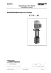
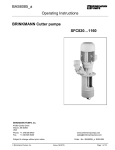
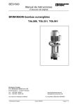
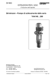
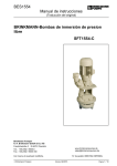
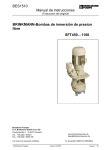
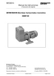
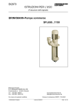
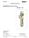
BE2510 Operating Instructions Brinkmann Immersions pumps of the series STE/STL143 ... 146 Contents 6 Start up / Shut down ..............................................2 7 Servicing and Maintenance ...................................3 8 Trouble shooter’s guide .........................................3 9 Spare parts ............................................................4 10 Replacing insert shaft ..........................................5 1 General.................................................................. 1 2 Safety .................................................................... 2 3 Transport and storage ........................................... 2 4 Description of product and accessories ................ 2 5 Installation ............................................................. 2 1 General These operating instructions apply to the pumps of the series STE/STL143 ... 146 with different depths of immersion and specifications. The immersion pumps are suitable for handling contaminated coolants, (and extremely inflated fluids / STL construction). These operating instructions contain basic information and instructions which must be observed when the pump is being installed, operated or repaired. Therefore it is important that these operating instructions are read by the fitter, the operator and relevant technical personnel before installation and start-up, and they are available at all times at the place where the unit/system is being operated. Specifications Max. del. pressure Max. del. volume bar / spec. weight 1 l/min STE143 / 190 STL143 / 220 270 300 340 370 420 450 510 540 620 650 3,9 185 STE144 / 220 STL144 / 250 300 330 370 400 450 480 540 570 650 680 5,3 STE145 / 270 STL145 / 300 350 380 420 450 500 530 590 620 700 730 STE146 / 300 STL146 / 330 380 410 450 480 530 560 Type Type Depth of immersion / STE h mm Weight STE STL kg Power 185 265 335 415 505 615 25 26 27 28 29 30 27 28 29 30 31 32 1,5 190 220 300 370 450 540 650 26 27 28 29 30 31 28 29 30 31 32 33 1,7 6,6 195 270 350 420 500 590 700 30 31 32 33 34 35 32 33 34 35 36 37 2,2 8,1 200 305 385 455 535 31 32 33 34 33 34 35 36 2,6 kW Depth of immersion STL = h + 30 mm Mediums Water, coolant, cooling- and cutting-oils Kinetic viscosity of the medium 1 .... 90 mm /s Temperature of medium 0 .... 60 °C (80 °C / STL) ....150 °C as special make / STE Noise level / 50 Hz STE143...STE146 2 68 dBA Measuring of noise level according to DIN 45635 at a distance of 1 m. Brinkmann Pumpen Edition 12/07 Page 1 of 5 2 Safety See appendix A. 3 Transport and storage Protect the pump against damage during transportation. Store pump in dry and protected areas and protect it against penetration of foreign bodies. 4 Description of the product and accessories Pumps of the series STE/STL143...146 are multi-stage rotary pumps. The impellers are fixed on the driving shaft extension. Pump and motor form a compact and space-saving unit. Pumps of this type are designed with semi-open impellers, (and a suction screw / STL construction). The motor is surface cooled and complies with the DIN IEC 34 resp. EN 60034 (IP 55). Tension voltage and frequency must correspond with the shown specification on the nameplate. The terminal links of the motor are delivered in star connection from the plant. A circuit breaker or overload trip must be provided and the tripping current must be adjusted to correspond with the motor rated current. Special electrical or mechanical versions are described in appendix B (separate sheet)! Check the terminal links according to the following wiring diagram. Star connection 3 x 400 V, 50 Hz resp. 380-420 V, 50 Hz Delta connection 3 x 230 V, 50 Hz resp. 220-240 V, 50 Hz Work on the electrical equipment must only be carried out by a qualified electrician. The motor must be isolated before any work is carried out. 5 Installation The pumps are mounted on the top of the coolant tank with the pump body being immersed in the coolant. Pumps must be mounted securely. The pipework must be installed so that no distortion of the pump can occur. According to the drawing shown on the right, the maximum liquid level must stay about 30 mm below the mounting flange. Also ensure that the minimal liquid level for the STE pump is 30 mm before starting up the motor. For the STL pump the suction hole of the pump body must be covered with liquid. The inlet is at the bottom of the immersed pump body. The distance between the inlet and the tank bottom must be so large that the inlet can not be blocked by deposits during longer shutdowns. To obtain the full flow rate it is recommended to choose for the pipework the nominal bore diameter of the pump’s cross section for connection. Therfore pipe bends should be used, not pipe angles! The pipework must be qualified for occuring hydraulic pressure! The pump must be mounted in such a way that rotating parts under the cover of the coolant tank can not be touched! 6 Start up / Shut down Start up Switch off at the main fuse. After connection of the terminals close the terminal box. Briefly start the motor and check the rotation according to the arrow on the top of the motor. Looking through the fan cover of the motor, the fan has to turn clockwise. If the direction is incorrect change over two of the power leads. Shut down Switch off at the main fuse. Open terminal box and disconnect the power leads Empty out the pump. BE2510 Edition 12/07 Page 2 of 5 The temperature of the medium is not allowed to be higher than 60 °C for STE and 80 °C for STL or 150 °C as special make for STE! The pumps are not suitable for continuous running against a closed sliding valve ( plan bypass ). The particle-size in the medium is not allowed to be bigger than 2.5 mm! ATTENTION Switching-on frequency: Motors less 3 kW max. 200 times per hour. 7 Servicing and Maintenance The surface of the motor must be kept free of dirt. The motor shaft is spinning in permanently greased ball bearings (with special grease and increased bearing play) and does not require any special maintenance. Spare parts are readily available from stock. 8 Trouble shooter’s guide Fault Cause Remedy Motor does not start, no motor noise At least two of the power supply leads have failed Check fuses, terminals and supply leads Motor does not start, humming noise One of the supply leads has failed Impeller faulty Motor bearing faulty See above Replace impeller Replace bearing Pump does not pump liquid level too low Pump mechanism faulty Pipe blocked Fill up liquid Replace pump mechanism Clean pipe Insufficient flow and pressure Wrong direction of rotation of impeller Pump mechanism silted up Worn pump mechanism Switch two power supply leads Clean pump mechanism Replace pump mechanism Power consumption is too high Wrong direction of rotation of impeller Lime or other deposits Mechanical friction See above See above Repair pump Spare parts are available from the supplier. Standard commercially available parts are to be purchased in accordance with the model type. The ordering of spare parts should contain the following details: 1. Pumptype e.g. STE145 / 370 2. Pump No. e.g. 01042510 The date of the construction year is a component of the pump’s type number. 3. Voltage, Frequency and Power Take item 1, 2 and 3 from the nameplate 4. Spare part with item No. e.g. Inlet cover item No. 52 Brinkmann Pumpen K. H. Brinkmann GmbH & Co. KG Friedrichstraße 2 D-58791 Werdohl Tel.: +49-2392 / 5006-0 Fax: +49-2392 / 5006-180 www.BrinkmannPumps.com [email protected] Subject to change without prior notice. BE2510 Order - No.: BE2510 ENGLISH Edition 12/07 Page 3 of 5 9 Spare part list for the immersion pumps of the series STE/STL143 ... 146 Item 1 2 3 4 7 8 9 10 11 13 14 15 16 17 19 50 51 52 52 53 53 54 55 56 57 58 59 60 61 62 63 64 65 66 68 69 70 71 72 73 74 75 82 83 84 85 86 87 90 91 Description Stator with terminal board Motor flange End shield Terminal box Fan Fan cover Ball bearing Ball bearing Gasket Parallel pin Thread rolling screw Slotted cheese head screw Socket head cap screw Socket head cap screw Retaining ring Pump body Motor shaft with rotor Inlet cover for STE Intake cover for STL Pump plate for STL Pump plate for STE Flow plate for STE Intermediate Cover Bearing stage STE/STL145...146 Impeller Suction screw only for STL Distance liner Distance liner Distance liner Running sleeve Bearing bush Distance plate Woodruff key O-ring Splash ring Shaft seal Hexagon head screw STE/ STL143 Stud bolt STE/STL144...146 Hexagon domed cap nut STE/STL144...146 Distance bolt STE/STL144...146 Washer only for STE Hexagon thin nut only for STE Joining socket Socket head cap screw Spring washer O-ring Screw plug Sealing ring Shaft clamp Insert shaft DIN 625 DIN 625 DIN DIN DIN DIN DIN 7 7500 84 912 912 DIN 6888 DIN 931 DIN 1587 DIN 439 DIN 912 DIN 7980 DIN 908 DIN 7603 Tightening torques for screwed connections Thread - ∅ M4 Strength classes 4.8 Tightening torque 1 Nm in Nm BE2510 M6 M8 4.8 M5 8.8 8.8 8.8 2 Nm Item 15 3 Nm Item 14 and 16 4.5 Nm Item 70, 72 4.5 Nm 20 Nm Item 17 Edition 12/07 M12 30 Nm Item 83 30 Nm Item 75 Page 4 of 5 10 Repair Instructions / Replacing shaft clamp and shaft 3 1 2 1 = Shaft clamp 2 = Insert shaft 3 = Motor shaft Dismantling the insert shaft - Disconnect the immersion pump from the mains both electrically and mechanically. - Set the pump down on the fan cover. Dismantle the pump unit and the pump body. - Loosen the screws on the shaft clamp (1) one after the other. Note: Do not, under any circumstances, remove the screws completely, danger of injury! - Pull the insert shaft (2) and the shaft clamp (1) off the motor shaft (3). Mounting the insert shaft - Set the motor down on the fan cover. - Position the shaft clamp (1) (use a new shaft clamp) in the centre of the cranked clamping diameter (2) of the insert shaft. - Insert the motor shaft (3) into the insert shaft (2). Tighten: - Mark the first screw and tighten all the screws evenly by hand, one after the other in a clockwise direction (not cross-ways). - Use a torque screwdriver to tighten each screw first with 2 Nm then with 3.5 Nm and finally with 5 Nm (in a clockwise direction again). - Mount the pump body. Further assembly is carried out as before. Note: Note torques for the screw connections! When putting the pump back into use, make sure the direction of rotation is correct! BE2510 Edition 12/07 Page 5 of 5