1
Floor Mixing Unit Installation and Commissioning Instructions
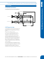
2.5 Hydraulic connections
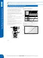
Connect the primary flow and return pipes and each of
the individual circuits, as shown in the example below.
Manual Air Vents
Return balancing valve
Primary flow
Lockshields
Primary return
Drill / Fill valves
2.6 Filling and testing
The manifolds are provided with double regulating valves
supplied fitted with either lockshields or flowmeters
as standard and a return balancing valve in the closed
position.
Floor Mixing Unit Operating Instructions
2. Installation
Open them before filling the system.
For filling, use the adjustable drain/fill valves with
3⁄4” connection located at the beginning of the low
temperature flow rail, and at the end of the low
temperature return rail, letting out the air contained
inside the system by means of 2 manual air vent
valves and the drain and filling valve located on the low
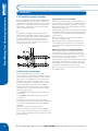
temperature return rail. First check that return balancing
valve, component 7 on page 2, is completely open. If
it is not, open by turning the nut under the cap using a
10mm socket. Please make sure you compeletly open
the balancing adjustment screw in the centre of the nut,
using a screwdriver.
We recommend filling each circuit separately, opening
the relative valves and double regulating valves each time
and closing them again when the operation is completed.
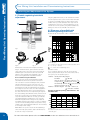
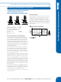
The following commissioning instructions show
separately the different procedures for setting up the
designed flow rate using either lockshields or flowmeters
For more information please call us on 01993 824900 or view our website at www.emmeti.co.uk
7