1
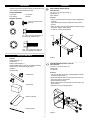
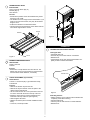
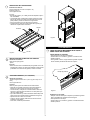
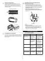
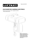
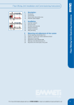
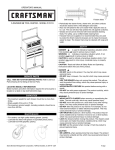
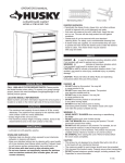
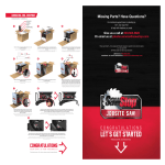
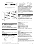
OPERATOR’S MANUAL
R
Ball bearing slides
Model # 81338 36” (7)-Drawer Cabinet
Model # 2915 46” (13)-Drawer Cabinet
Friction slides
• Periodically the drawer fronts, drawer trim, and other surfaces
should be cleaned with a mild detergent and water.
• Auto wax will preserve the unit’s luster finish. Apply the wax as to
a car. The wax will also help protect the unit against scratches.
• Grease and oil can be removed with most standard cleaning
fluids. For safety, use a nonflammable cleaning fluid.
• If drawer liners are supplied, it is recommended they are used
to protect the finish inside the drawers and to make the drawers
easier to clean. The drawer liners may be cleaned with soap and
water.
safety
service parts
Call 800.366.7278 for Service Parts. Refer to Service
Parts Drawing for full listing of Service Parts.
Locating Model # Information
Model numbers and other information required for service parts is
located on a label on the interior right side of the top most drawer.
capacities
• Empty weight of 36” cabinet is 308 lbs.
• Empty weight of 46” cabinet is 472 lbs.
• The maximum product weight, including contents, for the 36”
model should be no more than 1800 pounds.
• The maximum product weight, including contents, for the 46”
model should be no more than 3000 pounds.
• The maximum weight for each (2) inch deep drawer is (120)
pounds.
• The maximum weight for each (3) inch deep drawer is (200)
pounds.
• The maximum weight for each (4) - (6) inch deep drawer is
(320) pounds.
• The maximum weight for each drawer (9) inches deep or more
is (400) pounds.
maintenance
• For casters, use high quality bearing grease, (yearly).
• Lubricate the slides with grease or equivalent,(twice yearly.)
• Lubricate lock and locking system components with graphite,
(yearly).
DANGER
is used to indicate a hazardous situation which,
if not avoided, will result in serious injury or death.
WARNING
indicates a hazardous situation which, if not
avoided, could result in serious injury or death.
Caution is used to indicate a hazardous situation which, if not
avoided, may result in minor injury, moderate injury, or property
damage.
CAUTION: Read and follow all Safety Rules and Operating
Instructions before first use of this product.
danger
• DO NOT stand on this product. You may fall or cause product
to tip.
• DO NOT open more than one drawer. The product may become unstable and tip.
• DO NOT step in the drawers. You may fall or cause product to
tip.
• DO NOT mount this product on a truck bed or any other moving
object.
• DO NOT move the product prior to closing and locking all the
drawers. The drawers could come open and make the product
unstable and tip.
warning
• WEAR SAFETY GLASSES when removing or repositioning
the slides.
• DO NOT pull this product when moving it. Push the product to
prevent personal injury.
• USE THE BRAKES when not moving this product. This will
prevent the product from rolling.
• DO NOT alter this product in any manner. For example, do not
weld external lockbars or attach electrical equipment.
• Keep the product on level surfaces. The product may become
unstable and tip if stored or moved on an uneven surface.
• BE CAREFUL when closing the cover. Remove hands before
the cover closes completely.
caution
• This product is not designed to be directly lifted with a fork lift,
or to be towed with any mechanical devices.
• The maximum weight for each drawer should never be exceeded.
• Only transport this product empty. Properly secure when
transporting.
• DO NOT exceed maximum product weight, including contents.
See Operations Sections: Capacities for more information.
Use adequate manpower when lifting or moving the chest or cabinet.
Distributed by Sears Brands Management Corporation, Hoffman Estates, IL 60179
Rev A - F1848
hardware
ASSEMBLY
side handle INSTALLATION
Hardware and other included contents can be found in the
bottom drawer (unless otherwise noted).
Tools Required:
3/8” wrench
5/16" wrench
Items Needed:
1/4 - 20 x 1-1/2" Hex Screw (Qty: 4)
Handle (Qty: 1)
3/8-in Wrench
1/2” wrench
Scissors
Process:
• Attach (1) handle endcap using (2) screws. Tighten with
a wrench.
• Align handle with notches in attached endcap, hold in
position.
• Align notches in second handle endcap and attach using
(2) screws. Tighten with a wrench.
• To remove, reverse the procedure.
Hardware Included:
10-24 x 5/16 Hex Screw
(Qty: 24)
1/4 - 20 x 1-1/2 Hex Screw (Qty: 4)
(Included with Handle Pack.)
Screw
Handle
5/16 - 18 x 1 Hex Screw (Qty: 16)
(Only included with 36" Cabinet.)
Carton Contents
Figure 1
Cabinet:
Handle Pack (Qty: 1)
Caster pack
Drawer Liner Roll (Qty: 1)
Drawer Dividers (Qty: 6) (for the 46" Cabinet, dividers
can be found in the top full length drawer.)
Literature
Hardware bag
CASTER INSTALLATION (if required)
Items Needed:
5/16-18 x 1 Hex Screw (Qty: 16)
Caster Pack
1/2" Wrench
Process:
• Lay the cart down on its back. (Use packaging material
to protect the paint finish.)
• Mount both swivel casters on the same side of the cart
using (4) screws on each caster.
• Wrench tighten all screws.
• Mount rigid casters to the opposite end of the cart in the
same manner.
• Return the unit to its upright position.
Handle Pack
Caster Pack
Drawer Liner Roll
Drawer Divider
Figure 2
2
divider INSTALLATION
Items Needed:
10-24 x 5/16 Hex Screw (Qty: 8)
Dividers (Qty: 6)
5/16" Wrench
Process:
• Decide which position and in which drawers they would
best serve your needs.
• The dividers are cut to fit right to left in the drawers. If you
prefer to run them front to back, they may be trimmed in
length to do so.
• Position the dividers in the desired locations.
• Thread screws through the bottom of the drawer and into
each divider. Tighten all the screws.
Drawer
Dividers
Figure 4
operation
LOCKING AND UNLOCKING THE Unit
Figure 3
Locking the Unit:
• Pull handle lever out.
• Insert the key into the lock and turn it clockwise.
• Release lever.
• If the drawers do not open, push all the drawers completely closed to release the lockbars
Screw
drawer liner INSTALLATION
Items Needed:
Drawer Liner Roll
Scissors
Process:
• Remove the non-slip drawewr liner from the roll. The
drawer liner may be cut with scissors to fit each drawer
and around the drawer divideres, if necessary.
Handle Lever
chest attachment (if purchased)
Items Needed:
5/16-18 x 1 Hex Screw (Qty: 4) [included with chest]
5/16 Wrench
Process:
• Remove the wooden top from the cart.
• Remove the top two drawers of the cart (refer to the
drawer removal instructions).
• Lift the chest onto the cart. Line up the holes in the bottom of the chest with the holes in the top of the cart.
• Attach the chest using (4) screws inserted from the
underside of the top of the cart. (See Figure 8)
• Wrench tighten all screws.
• Replace the drawer (refer to drawer installation instructions).
• To remove, reverse procedure.
Figure 5
Unlocking the Unit:
• Always check the unit to make sure all the drawers are
completely closed before locking.
• Pull the handle lever.
• Insert key into the lock and turn it counterclockwise.
• Release lever.
3
operation
removing and installing drawers
• Empty the drawer.
• Fully extend the drawer.
Friction Style - Fully extend the drawer. Insert screwdriver
into the slot in the side and push in on the stop until it
clears the lance. Pull drawer just past lance before
releasing stop. Repeat the process for the other slide.
Release Left
Release Right
Figure 6
BALL BEARING SLIDES
Lever Style - Lift or lower (depending on the slide) the
release lever on both sides, (this allows the slides to ride
over the stops.) Pull out to remove.
Friction slide - Fully extend slides in cabinet. Hold the
slide on the cabinet while aligning it with the slide on
drawer. Push the drawer into the unit until the drawer
fully engages slides. Open drawer and reclose to ensure
proper operation. (If stop does not engage slide, lightly
deflect the stop with screwdriver.)
Slide
Stop
Tab Style - Depress the release tabs on both sides,
(this allows the slides to ride over the stops).
Pull out to remove.
removing and installing slides
Slide Removal • The drawers in these units can be rearranged to fit your
specific needs. This means that drawers may be moved
or replaced as desired. For example, a 6-inch drawer
may be replaced by a 2-inch and a 4-inch drawer, or
three 2-inch drawers.
• First remove the drawer (Refer to Operation A).
• Lift and hold the spring retainer, and push the slide toward the rear of the unit. The slide may now be removed.
reINSTALL drawers
Ball bearing slide - Pull slides and slide carrier out to fully
extended position (see illustration.) Hold the slide on the
cabinet while aligning it with the slide on drawer. Slightly
insert one side and repeat for the other side. Slowly push
drawer to its fully closed position to engage slide. Open
drawer and reclose to ensure proper operation.
slide carrier
slide
Spring Retainer
Slide Installation • Place the slide in the appropriate position in the unit and
pull toward the front of the unit until the spring retainer
snaps into position and secures the slide.
• For smooth operation, make sure that the drawers are
matched with their original slides.
troubleshooting
lock system
self closing slides
The self closing feature will pull the drawer closed when
the drawer is pushed past the slide detent. This is located
approximatley 1/2" from the fully closed position.
Problem
Cause
Solution
The unit unlocks
but the drawers
still will not open.
One or more
of the drawers
are holding the
lockbars from
releasing.
Completely close
all the drawers and
the lockbars will
release to open the
drawers.
The cover on the
chest is holding
the lockbars from
releasing.
Apply a downwardpressure to the
top of the cover
to let the lockbars
release.
The release
cables are not
working.
In an UNLOCKED
position and pull
the lock lever several times.
The unit is leaning Position the unit on
too far forward.
a level area.
The unit locks but
some drawers still
are not locked.
5
One or more of
the drawers are
not compeletly
closed.
Unlock the unit.
Close all drawers
completely. Relock
unit.
MANUAL DE USUARIO
R
MODELO NO 81338 gabinete de 36in (91,4 cm)
con (7) cajones
MODELO NO 2915 gabinete de 46in (116,8 cm)
con (13) cajones
Cojinetes de bolas
Correderas de friccion
• Lubrique la cerradura y la fijación de componentes de sistema con el
grafito, (anualmente).
• Limpie con detergente suave y agua los frontales y los bordes laterales
de los cajones y las demás superficies.
• La cera para automóviles preservará el acabado brilloso de la unidad.
Aplique la cera como lo haría al carro. La cera también ayudará a proteger la unidad contra raspones.
• La grasa y el aceite pueden retirarse con la mayoría de los líquidos
estándar para limpieza. Por razones de seguridad, utilice un líquido
incombustible para limpieza.
• Si se suministran forros para las gavetas, se recomienda que se utilicen
para proteger el acabado interno de las mismas y para facilitar la limpieza. Los forros para gavetas pueden limpiarse con agua y jabón.
SEGURIDAD
PELIGRO
Piezas de servicio
En estados Unidos llame al 1-800-659-7084 para
piezas de repuesto. Fuera de Estados Unidos
llame a su distribuidor local. Suministre el número de
modelo al comunicarse.
UBICACIÓN DE INFORMACIÓN DEL No. DE MODELO
El número de modelo y demás información requerida para las piezas de
servicio se encuentran en una etiqueta en el lado interior derecho de la
gaveta superior.
CAPACIDAD
• El peso vacío del gabinete de 36” (91,4 cm) es 308 lbs (139,7 Kg.)
• El peso vacío del gabinete de 46” (116,8 cm) es 472 lbs (214 Kg.)
• El peso máximo del producto, incluyendo el contenido, para el modelo
de 36” (91,4 cm) no debe ser mayor de 1800 libras (816,5 Kg.).
• El peso máximo del producto, incluyendo el contenido, para el modelo
de 46” (116,8 cm) no debe ser mayor de 3000 libras (1360,8 Kg.).
• El peso máximo para cada gaveta es 2” (5cm) de profundidad es 120
libras (54,4 Kg.).
• El peso máximo para cada gaveta de 3” (7,6 cm) de profundidad es
200 libras (90,7 Kg.).
• El peso máximo para cada gaveta de 4” (10,2 cm) - 6” (15,2 cm) de
profundidad es 320 libras (145,1 Kg.).
• El peso máximo por cada gaveta de 9” (22,9 cm) de profundidad o
más es 400 libras (90,7 Kg.).
MANTENIMIENTO
• Para las ruedas, utilice grasa para rodamientos de alta calidad (anualmente).
se utiliza para indicar una situación
peligrosa que, de no evitarse, resultará en lesiones graves o la muerte.
ADVERTENCIA
indica una situación peligrosa que, de no
evitarse, podría producir lesiones graves o la muerte.
PRECAUCIÓN se utiliza para indicar una situación peligrosa que, de
no evitarse, puede derivar en lesiones leves o moderadas, o en daño a la
propiedad.
ATENCIÓN: Lea y siga todas las Normas de Seguridad y las
Instrucciones de Funcionamiento antes de utilizar por primera vez este
producto.
PELIGRO
•N
O se ponga de pie sobre esta unidad. Puede caerse u ocasionar que
el producto se vuelque.
•N
O abra más de una gaveta. El producto podría quedar inestable y
volcarse.
•N
O utilice las gavetas como peldaños. Puede caerse u ocasionar que
el producto se vuelque.
•N
o monte este producto en una cama de carro o ninguÌn otro objeto
móvil.
•N
O mueva la unidad antes de cerrar y asegurar todas las gavetas. Las
gavetas podrían abrirse y hacer que la unidad se vuelva inestable y se
vuelque.
ADVERTENCIA
• USE
GAFAS DE SEGURIDAD al quitar o volver a poner las corred-
eras.
• NO hale la unidad, empújela cuando la mueva.
• UTILICE LOS FRENOS cuando el producto no esté en movimiento Esto
impedirá que se deslice.
•N
O altere la unidad en modo alguno. Por ejemplo, no suelde las barras
de sujeción externas ni le incorpore equipos eléctricos.
• Mantenga la unidad en superficies niveladas. La unidad puede tornarse
inestable y volcarse si se almacena o se moviliza en una superficie no
nivelada.
• TENGA cuidado cuando cierre la tapa. Quite las manos antes de que la
tapa cierre completamente.
PRECAUCIÓN
• Este producto no está diseñado para ser levantado directamente con un
montacargas, ni para ser remolcado con unidades mecanizadas.
• Nunca debe exceder el peso máximo de cada gaveta.
• Sólo transporte esta unidad cuando esté vacía. Asegúrela adecuadamente cuando la transporte.
• NO exceda el peso máximo del producto, incluyendo el contenido. Refiérase a las Capacidades para más información.
• Lubrique las diapositivas con grasa o equivalente, (dos veces cada año.)
Utilice el personal adecuado para levantar o
mover el baúl o el gabinete.
Distribuido cerca Sears Brands Management Corporation, Hoffman Estates, IL 60179
Rev A - F1848
FERRETERÍA
ENSAMBLAJE
INSTALACIÓN DE LA MANIJA LATERAL
El hardware y otros contenido incluidos pueden ser encontrados
en el ajuar (a menos que se indique lo contrario).
Elementos necesarios:
Tornillo Hexagonal de 1/4-20 X 1 1/2 (Cant.: 4)
Manija (Cant.: 1)
Llave Inglesa de 3/8”
HERRAMIENTAS NECESARIAS:
Llave Inglesa de 3/8”
Llave Inglesa de 5/16”
Llave Inglesa de 1/2”
Tijeras
Proceso:
• Fije (1) remate terminal de manija utilizando (2) tornillos.
• Apriete con una llave.
• Alinee la manija con las muescas en el remate terminal, sosténgala en posición.
• Alinee las muescas en el remate terminal de la segunda manija
y fije utilizando (2) tornillos. Apriete con una llave.
• Para quitarlo, deshaga los pasos anteriores.
FERRETERIA INCLUIDAS:
Tornillo Hexagonal de 10-24
x 5/16 (Cant: 24)
Tornillo
Manija
Tornillo Hexagonal de 1/4 - 20 x 1-1/2 (Cant: 4)
(Incluido con el paquete de la minija.)
Tornillo Hexagonal de 5/16 - 18 x 1 (Cant: 16)
(Sólo incluido con el gabinete de 36" (91,4 cm).)
Figura 1
CONTENIDO DE LA CAJA DE CARTÓN
COLOCACIÓN DE LAS RUEDAS (si fuese necesario)
Paquete de manija (Cant.: 1)
Paquete de ruedas
Rollo de forro para gaveta (Cant.: 1)
Divisores de gaveta (Cant.: 6) (Para los gabinetes de 46” (116,8
cm) puede encontrar divisores de gabinete en la gaveta superior
de largo total.)
Bolsa de accesorios
Material impreso
Elementos necesarios: (si fuese necesario)
Tornillo hexagonal de 5/16-18 x 1 (Cant.: 16)
Paquete de ruedas
Llave Inglesa de 1/2”
Proceso:
• Recueste la unidad rodante sobre su parte posterior. (Utilice el
material de empaque para proteger el acabado de la pintura.)
• Monte ambas ruedas giratorias en el mismo lado de la unidad
rodante utilizando (4) tornillos en cada rueda.
• Apriete todos los tornillos con una llave.
• Monte ruedas rígidas en el lado opuesto de la unidad rodante
de la misma forma.
• Vuelva a colocar la unidad en su posición vertical.
Paquete de manija
Paquete de ruedas
Rollo de forro para gaveta
Figura 2
Divisor de gavetas
2
INSTALACIÓN DE LOS DIVISORES
Elementos necesarios:
Tornillo hexagonal de 10-24 x 5/16 (Cant.: 24)
Divisores (Cant.: 6)
Llave Inglesa de 5/16”
Proceso:
• Decida qué posición y en cuáles gavetas se adaptarán mejor a
sus necesidades.
• Los divisores están cortados para encajar de derecha a izquierda en las gavetas. Si prefiere colocarlos del frente hacia la
parte posterior, pueden recortarse a lo largo también.
• Coloque los divisores en las ubicaciones que desee.
• Inserte tornillos a través de la parte inferior de la gaveta y en
cada divisor. Apriete todos los tornillos.
Gaveta
Divisores
Figura 4
FUNCIONAMIENTO
Figura 3
CÓMO UTILIZAR EL MECANISMO DE BLOQUEO Y
DESBLOQUEO DE LA UNIDAD
Tornillo
PONER SEGURO A LA UNIDAD:
• Hale la palanca de la manija hacia afuera.
• Inserte la llave en la cerradura y gírela en el sentido horario.
• Suelte la palanca.
• Si las gavetas no abren, empuje todas las gavetas completamente cerradas para liberar las barras de sujeción.
INSTALACIÓN DEL FORRO DE LAS GAVETAS
Elementos necesarios:
Rollo de forro para gaveta
Tijeras
Proceso:
• Retire del rollo el forro antirresbalante para gavetas. El forro de
gaveta puede cortarse con tijeras para adaptarlo a cada gaveta
y alrededor de los divisores de gavetas, si fuese necesario.
Manija tipo palanca
ACCESORIO DE BAÚL (si lo adquiere)
Elementos necesarios:
Tornillo hexagonal de 5/16-18 x 1 (Cant.: 4) [se incluye con el
baúl]
Llave Inglesa de 5/16”
Proceso:
Retire la parte superior de madera de la unidad rodante.
• Retire las dos gavetas superiores de la unidad rodante (refiérase a las instrucciones para remoción de gavetas).
• Levante el baúl y colóquelo en la unidad rodante. Alinee los
agujeros en la parte inferior del baúl con los de la parte superior de la unidad rodante.
• Fije el baúl utilizando (4) tornillos insertados desde abajo de la
parte superior de la unidad rodante. (Refiérase a la figura 8).
• Apriete todos los tornillos con una llave.
• Vuelva a colocar la gaveta (refiérase a las instrucciones de
instalación de la gaveta).
• Pare retirar, invierta el procedimiento.
Figura 5
Desbloqueo de la unidad:
• Siempre revise la unidad para comprobar que todas las gavetas
estén completamente cerradas antes de asegurar.
• Hale la palanca de la manija.
• Inserte la llave en la cerradura y gírela en el sentido antihorario.
• Suelte la palanca.
3
Estilo fricción - extienda completamente la gaveta. Inserte el
REMOCIÓN E INSTALACIÓN DE GAVETAS
destornillador en la ranura del costado y presione el tope hasta
que libere el rejón. Hale la gaveta justo después del rejón antes
de liberar el tope. Repita el proceso con la otra corredera
• Vacíe la gaveta.
• Abra completamente la gaveta.
Libere la izquierda
Libere la derecha
Figura 6
COJINETES DE BOLAS
Estilo palanca – Levante o baje (dependiendo de la corredera)
la palanca de liberación en ambos lados (esto permite que las
correderas pasen sobre los topes). Jale hacia afuera para retirar.
Corredera de fricción: extienda completamente las
correderas en el gabinete. Sostenga la corredera en el gabinete
mientras lo alinea con la corredera de la gaveta. Empuje la gaveta en la unidad hasta que la gaveta se enganche completamente
en las correderas. Abra la gaveta y vuelva a cerrarla para asegurarse de que funcione correctamente. (Si el tope no se engancha
en la corredera, dóblelo ligeramente con un destornillador.)
Corredera
Tope
Estilo lengüeta – Oprima las lengüetas de liberación en ambos
lados (esto permite que las correderas pasen sobre los topes).
Jale hacia afuera para retirar.
4
QUITANDO E INSTALACIÓN DE DIAPOSITIVAS
instalación de gavetas
Remoción de la corredera -
Correderas de rodamientos esféricos - hale hacia
• Las gavetas de estas unidades pueden disponerse de otro
modo para que se adapten a sus necesidades específicas.
Esto significa que las gavetas pueden moverse o reemplazarse
como lo desee. Por ejemplo, una gaveta de 6” (15,2 cm) puede
reemplazarse por una gaveta de 2” (5 cm) y de 4” (10,2 cm), o
tres gavetas de 2” (5 cm).
• Primero retire la gaveta (Refiérase a la Operación A).
• Levante y sostenga el retenedor con muelle y presione la corredera hacia la parte posterior de la unidad. La corredera podrá
retirarse ahora.
afuera las correderas y el soporte de las correderas hasta que
queden en posición totalmente extendida (ver ilustración).
Sostenga la corredera en el gabinete mientras lo alinea con la
corredera de la gaveta.
Soporte de las correderas
Corredera
Reten flexible
Figura 7
Instalación de la corredera • Coloque la corredera en la posición adecuada en la unidad
y hale hacia el frente de la misma hasta que el retenedor de
resorte encaje en su posición y asegure la corredera.
• Para un funcionamiento suave, cerciórese de que las gavetas
correspondan con sus correderas originales.
soluciÓn de problemas
DEL SISTEMA DE CIERRE
CORREDERAS AUTOCERRANTES
La característica de cierre automático tirará del cajón cerrado cuando el cajón se empuja más allá de la muesca de la diapositiva.
Éste es aproximadamente localizado 1/2” de la posición completamente cerrada..
Problema
Causa
Solución
La unidad puede
desbloquearse pero las
gavetas no abren.
Una o más de las
gavetas está(n)
evitando que las
barras de sujeción
se liberen.
Cierre completamente
todas las gavetas y
las barras de sujeción
se liberarán para abrir
las gavetas.
La cubierta del
baúl está evitando
que las barras de
sujeción puedan
liberarase.
Aplique una presión
hacia abajo en la
parte uperior de la
cubierta para permitir
que las barras de
fijación puedan liberarse.
Los cables de
liberación no están
funcionando.
En la posición DESBLOQUEADA hale la
palacea de aseguramiento varias veces.
La unidad se inclina
demadiado hacia
delante.
Coloque la unidad en
un area nivelada.
Una o más gavetas
no están completamente cerradas.
Desbloquee la unidad.
Cierre todas las gavetas completamente.
Vuelva a asegurar la
unidad.
La unidad se asegura
pero algunas gavetas
aún no están bloqueadas.
5