1
3.2 Mounting instructions
•
•
•
•
•
•
Never carry out welding or drilling work near the meter.
Leave the meter in its original package until all connections, insulating, painting and cleaning tasks have been performed.
Always install the meter according to the mounting position indicated on the nameplate (supply or return).
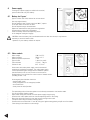
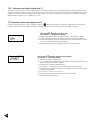
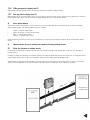
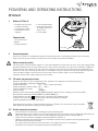
The flow meter may be installed either horizontally or vertically, but not upside down.
The heat meter must be protected against shocks and vibrations which might occur at the place of installation. When charging
the pipes with water, isolation valves must be opened slowly.
Thread and flange connections of the meter must match with the nominal width DN and nominal pressure PN
(according to EN 1092) of the corresponding counterparts of the pipes. The metering unit must not be subject to excessive
tensions caused by pipes or molded parts. The pipes of the heating system must be secularly fastened before and after the
flow meter. In case of flange connections, all bolts must be used and tightened. All bolts, nuts and gaskets used must comply
with the nominal width DN, the pressure level PN, the maximum admissible temperature and pressure.
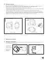
Flow direction, e.g. rising pipe
Flow direction
+ 45°
- 45°
Vertical mounting
4.
4.1
Horiztonal mounting
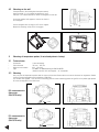
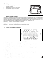
Mounting of the integrator
Mounting of the integrator
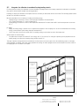
The integrator must not be installed with the flow meter when environmental temperature is permanently above 55 °C or in
case of operation for cooling purposes.
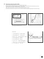
Rotate 45°
Set metering unit
with an angle of
45° on the support
Rotate metering
unit 45° till it
engages.
3