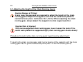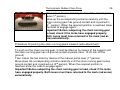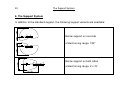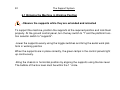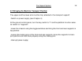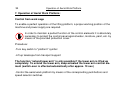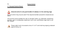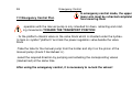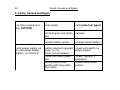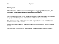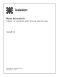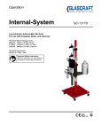
1
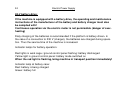
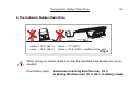
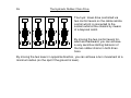
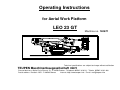
Operating Instructions
for Aerial Work Platform
LEO 23 GT
Machine no. 140671
Technical specifications are subject to change without notification
TEUPEN Maschinenbaugesellschaft mbH
Place of business: Marie-Curie-Strasse 13 - D 48599 Gronau - Telephone 02562 / 8161-0 - Telefax 02562 / 8161-888
Postal address: Postfach 1951 - D 48580 Gronau
Internet: http://www.teupen.info - E-mail: [email protected]
Copyright!
The copyright relating to these operating instructions remains with
TEUPEN Maschinenbaugesellschaft mbH
These operating instructions are intended for use by the owner of the machine and
their staff only.
The owner of the machine may copy these operating instructions for internal purposes only.
11.04.08 TEUPEN Maschinenbaugesellschaft mbH
Table of Contents
3
Contents
1. Introduction
1.1 Proper use
1.2 Explanation of symbols used
Page 5-6
Page 6
Page 7
2. Safety instructions and warnings
Page 8-12
3. Particular features
3.1 Technical data
3.2 Position of control elements
Page 13-14
Page 15-18
Page 19-21
4. Electrical power supply
Page 22-24
5. The hydr. rubber chain running gear
5.1 Driving by means of the hydr. rubber chain drive
5.2 Adjusting the height of the chain running gears
Page 25-26
Page 27
Page 28-29
4
Table of Contents
6. The support system
6.1 Bringing the machine in working position
6.2 Bringing the machine in transport position
Page 30-31
Page 32
Page 33
7. Operation of aerial work platform
7.1 Ground control
7.2 Emergency control platform/chassis
Page 34-35
Page 36-37
Page 38-39
8. General maintenance instructions
8.1 Lubrication plan
8.2 Oil recommendation
8.3 Oil levels
8.4 Maintenance instructions for live ring, general
Page 40
Page 40-41
Page 42-43
Page 44-45
Page 46-49
9. Faults, causes and repair
Page 50-55
10. Disposal
Page 56
Introduction
5
1. Introduction
The purpose of these operating instructions is to provide the owner of the Aerial
Work Platform with information on the correct handling, use and maintenance of the
machine. In order to ensure a proper and safe operation of the aerial work platform,
please read these operating instructions carefully and follow the instructions given in
these operating instructions strictly.
These operating instructions contain important information on how to operate the
aerial work platform in a safe, proper and efficient manner. Comply with these instructions strictly to avoid hazards, reduce repair costs and downtimes and to increase the service life of the aerial work platform.
This aerial work platform complies with „BGG 945“ of the "Hauptverband der
gewerblichen Berufsgenossenschaften" and is manufactured in accordance with EN
280 "Mobile Elevation Platforms - Design Calculations and Stability Criteria".
In the case of plants which must be approved by official authorities, the owner must
have the machine inspected by accredited inspection authorities (TÜV/DEKRA) or authorized persons prior to first commissioning as well as at the specified inspection intervals.
Other national or international standards are not applied. Inspections according to
other standards must be carried out separately.
6
Introduction and Proper Use
In case structural or other modifications are carried out at the machine without
the manufacturer's express approval, the EU Declaration of Conformity shall
become invalid.
1.1 Proper Use:
The machine may only be used for the transport of persons and tools (up to the
permissible carrying capacity) to enable work at aerial locations (see technical data
sheet). Any other use exceeding the scope of use mentioned above shall be considered as an improper use. Teupen Maschinenbau GmbH shall not be held liable for
any damage resulting from such an improper use.
Proper use also includes in particular
• the compliance with all information given in the operating instructions
• the proper performance of the specified inspection and maintenance work
As we do our best to always keep our product up to date, we reserve the right to modify and upgrade our aerial work platforms at any time without notification.
Symbols Used
7
1.2 Symbols Used:
Two symbols are used in these operating instructions for highlighting important information:
Warning This symbol indicates
information the non-compliance
with which may result in serious
injuries or even death.
Fig. 1
CAUTION This symbol
indicates information, the
non-compliance with
which may result in the
machine being damaged
8
Safety Instructions and Warnings
2. Safety Instructions and Warnings!
The machine is produced according to the state of the art and the generally recognized safety regulations. However, the use of the machine involves certain hazards
which may result in serious injuries or even death as well as material damage of the
machine or other property. The machine may only be used
• for the specified purpose
• when it is in a perfect technical condition, in particular as regards the safety
equipment.
Any defects affecting the safety must be repaired immediately.
Safety Instructions and Warnings
Before commissioning the aerial work platform, please read these operating instructions carefully and comply with the following safety instructions and warnings. Any
non-compliance with these instructions and warnings may result in serious personal
and material damage.
In addition to these operating instructions, also comply with the enclosed operating and maintenance instructions of the manufacturers of the motor and
the chain running gear.
Safety devices, e.g. limit switches, must not be made ineffective.
Screwed joints marked yellow and limit switch fixtures must not be
loosened.
The valve settings may only be modified by qualified staff.
Any non-compliance will result in the warranty becoming null and
void.
9
10
Safety Instructions and Warnings
αmax. = 14,5° (26 %)
αmax. = 14,5° (26 %)
βmax. = 17° (30%)
βmax. = 14,5° (26%) >>Battery operation only
If the machine is used transverse to a slope,
nobody may stay downhill of the aerial work
platform. It is also dangerous to stay downhill
behind the aerial work platform while the machine is moving uphill.
In order to prevent the aerial work platform from
falling over, it is necessary to let down the support until they almost touch the ground.
Fig. 2
Safety Instructions and Warnings
11
400 N
Note
minimum age!
Do not climb on the
cage railings!
Maximum side
force 400 N
No vibrations or jerky
movements!
Fig. 3
12
Safety Instructions and Warnings
High Voltage!
Danger!
Note the flowing
traffic!
Secure parts
projecting in the
traffic area!
Fig. 4
Immediately stop using
the aerial work platform if
the wind speed exceeds
12,5 m /sec (wind force
6)!
The machine must not
be used as a crane,
hoist or
lateral pull!
Technical Data
13
3. Particular Features of the Aerial Work Platform
LEO 23 GT
•
Continuous proportional controls.
•
Upper and lower arm telescopeable.
•
Driven via diesel engine or battery
•
Starting/stopping the diesel engine is possible from the platform.
•
Sensitive electro-hydraulic distance control for chassis to enable exact positioning.
•
Width and height of chain running gear adjustable.
•
Narrow support on one side and narrow support on both sides.
•
Fuzzy control
•
Parallel guiding of the work cage by hydrostatic compensation system.
•
180°-turning work cage.
•
Eccentrically suspended work cage has the effect of an accessible cage arm.
14
Technical Data
•
Ergonomically shaped work cage with access opening.
•
Installation monitoring.
•
Covers above electric case and bottom control panel.
•
Start support transport position lower arm (prevents incorrect landing of the
lower arm in transport position).
Technical Data
15
3.1 Technical Data
LEO 23 GT
Working height:
Platform height:
Lateral reach at 200 kg:
Cage load:
Size of cage (lxwxh):
Turning cage:
Length:
Minimum passage width:
Height:
Dead weight:
Standard support area (lxw): (middle of support disk)
Min. support width (middle of support disk)
Max. support disk load per column
Area load in standard work position:
Turning range standard support:
Limited turning range (narrow on both sides):
Limited turning range (narrow on one side):
Supportable up to ground slope of:
Climbing ability (in driving direction):
(transverse to driving direction):
Driving speed:
Energy supply chain:
approx. 23.00 m
approx. 21.00 m
approx. 11.20 m
max. 200 kg
1.40 x 0.70 x 1.10 m
180°
min. 6.20 m
min. 0.98 m
min. 1.98 m
approx. 3000 kg
min. 4,10 x 4,30 m
min. 2,30 m
ca. 22,4 kN
2
ca. 1,8 kN/m
ca. 360°
2 x 15°
192°
ca. 26 %
ca. 30 %
ca. 26 %
ca. 1,5 km/h
internal
16
Technical Data
Beispiele Zugangstechnik
Korbdrehen 180░ - Korbanordnung aussermittig
Mauernische
Fig. 5
Satteldach
Mauervorsprung
Technical Data
17
Drive motor Kubota Z-602
Water-cooled 2-cylinder 4-stroke diesel engine
Volumetric displacement:
-1
Max. power at 3600 min :
Fuel type:
Noise emission:
3
599 cm
12.5 kW (17 PS)
Diesel fuel
approx. 89 dB (A)
Accessories
Electric motor EBS 90 L X 4
Rated input voltage:
Power consumption:
Power:
Additional weight:
230 V / 50 Hz
12.9 A
2.2 kW
approx. 25 kg
Alternative battery drive
Rated input voltage of battery charger:
Hydraulic unit:
Additional weight:
230 V / 50 Hz
48 V / 6 kW
approx. 180 kg
18
Fig. 6
Technical Data
Position of Control Elements
19
3.2 Position of Control Elements
Control panel in work cage with control
elements for platform, support and chain
functions
Turn key switch on the front left of the
control panel to "Platform" symbol"
Ground control panel with control
elements for platform, support and
chain functions
Turn key switch to "I", turn key switch at
work cage to "0"
20
Position of Control Elements
Box level for level alignment of the aerial
work platform
Locking mechanism for supports (wide
and narrow), make sure in any case
that the supports are locked correctly !
Drive motor case (OPTION)
(Fuel refill cutout in lid, filling level indicator on opposite side)
Position of Control Elements
21
Hydraulic tank, 230-V connection and
control box
Manual pumps for emergency control of
platform and supports
Cable remote control for chain functions
with fast/slow change-over
(if not used, insert jumper in any case)
22
Electric Power Supply
4. Electric Power Supply
Power is supplied either via the local mains network
using an extension cable (230 V) or by the mainsindependent drive motor.
As an alternative, a battery drive is also possible.
If an extension cable is used, connect the plug to the
socket of the extension cable.
Length of cable :
2
max. 40 m with 3 x 2.5 mm
max. 80 m with 3 x 4.0 mm2
Electric Power Supply
23
To start the drive motor, press the pushbutton with the spiral symbol until the
preheating indicator (yellow spiral symbol) goes out (comply with operating
instructions of engine manufacturer!)
Start power supply by drive engine:
- Start of drive engine at electric control box or in work cage
Turn key switch to the right until the engine starts
Avoid unnecessary starting: Voltage drop of
starter battery
Stop power supply by drive engine:
-Stop of drive engine at electric control box or in work cage,
Turn key switch to the left until the drive engine stops
24
Electric Power Supply
48-V battery drive:
If the machine is equipped with a battery drive, the operating and maintenance
instructions of the manufacturer of the battery and battery charger must also
be complied with!
Continuous operation via the electric motor is not permissible (danger of overheating)
Daily charging of the batteries is recommended if the platform is battery-driven. In
the case of a connection to 230 V (charger), the batteries are charged during operation. Thus the service time of the machine is increased.
Indicator lamps for battery operation:
Red lights in work cage / ground control panel flashing: battery discharged
Yellow light in ground control panel: battery mode switched on
When the red light is flashing, bring machine in transport position immediately!
Indicator lamp at battery case:
Red: battery is being charged
Green: battery full
The Hydraulic Rubber Chain Drive
25
5. The Hydraulic Rubber Chain Drive
αmax. = 14,5° (26 %)
αmax. = 14,5° (26 %)
βmax. = 17° (30%)
βmax. = 14,5° (26%) >>battery mode only
Fig. 8
When driving on slopes make sure that the specified slope angles are not exceeded!
Permissible slope:
transverse to driving direction max. 26 %
in driving direction max. 30 % (26 % in battery mode)
26
The Hydraulic Rubber Chain Drive
The hydr. travel drive controlled via
two control levers on the cable remote
control which is connected to the
socket outlet at the chassis by means
of a bayonet catch.
By moving the two control levers forward and backward, you can achieve
a very sensitive starting behavior of
the two rubber chains in both directions.
By moving the two levers in opposite direction, you can achieve a turn movement at a
minimum radius (on the spot if the ground is level).
The Hydraulic Rubber Chain Drive
27
5.1 Driving by means of the hydr. rubber chain drive
In order to drive through narrow aisles or doors, you can turn the work cage without
having to support the aerial work platform (control element at ground control, see
Chapter 3.2)
Driving by means of the rubber chain drive from the cage is only permissible up to a slope of 8° (15 %)
-Switch on power supply (see Chapter 4)
-Connect cable remote control to outlet at chassis and select the required
speed(symbol "hare" or "turtle")
-Switch toggle switch on ground control panel to "chain" symbol
-Move the two levers forward or backward at the same time to obtain a "forward/backward movement" and select the "speed"
-Move the levers in opposite direction to turn the machine in the required direction
-Interrupt power supply
28
The Hydraulic Rubber Chain Drive
5.2 Adjusting the Height of the Chain Running Gears:
Caution Danger of Tilting!
In any case, two persons are required to adjust the height of the chain
running gears! Adjust the supports such that the aerial work platform
cannot fall over (max. inclination 14.5°, 26 %)! When adjusting the chain
running gear, always adjust the supports to wide support position
Caution Risk of Injuries!
With narrow-adjusted chain running gear, never loosen the locks if the
aerial work platform is supported high (chain running gear shoots down)!
Procedure for pushing the chain running gears inward (narrow adjustment):
To push in the chain running gear, jack it up by means of the supports until the chain
running gear has no ground contact anymore (max. 10-20 mm off the ground)
The Hydraulic Rubber Chain Drive
29
Then loosen the two locks by means of the manual pump
lever (1st person).
Move up the corresponding columns carefully until the
chain running gear has ground contact and is pushed in
(2nd person). When the required position is reached, allow
the locks to engage again!
Important! Before subjecting the chain running gear
to load, check if the locks have engaged properly.
Both levers must have returned to the mark (red arrow) automatically.
Procedure for pushing the chain running gears outward (wide adjustment):
To push out the chain running gear, it must be lifted up by means of the support until
the chain running gear has no ground contact anymore (max. 10-20 mm off the
ground)
Then loosen the two locks by means of the manual pump lever (1st person).
Move down the corresponding columns carefully until the chain running gear looses
ground contact and is pushed out (2nd person). When the required position is
reached, allow the locks to engage again!
Important! Before subjecting the chain running gear to load, check if the locks
have engaged properly. Both levers must have returned to the mark (red arrow)
automatically.
30
The Support System
6. The Support System
In addition to the standard support, the following support variants are available:
Narrow support on one side
Limited turning range 192°
Narrow support on both sides
Limited turning range 2 x 15°
The Support System
31
Make sure that the ground is firm, if necessary, increase the support area by
means of planks. All supports must be loaded, the rubber chain running gears
must be free!
In order to increase the safety of the aerial work
platform in slopes (skidding, stability), the ground
disks must be aligned horizontally (see sketch).
This is also important in view of their limited ability
to adapt to the environment.
Anchoring the supports by means of chains, ropes,
ground anchors, etc. is not permissible.
26
32
The Support System
6.1 Bringing the Machine in Working Position
-Observe the supports while they are extended and retracted
To support the machine, position the supports at the required position and lock them
properly. At the ground control panel, turn the key switch to "I" and the platform function selector switch to "supports".
-Lower the supports evenly using the toggle switches and bring the aerial work platform in working position
When the supports are in place correctly, the green lamps in the control panels light
up continuously.
-Bring the chassis in horizontal position by aligning the supports using the box level.
The bubble of the box level must be within the 1° circle.
The Support System
33
6.2 Bringing the Machine Transport Position
The upper and the lower arm must be fully retracted in the transport support!
-Switch on power supply (see Chapter 4)
At the ground control panel, turn the key switch to "I" and the platform function selector switch to "supports".
-Lower the chassis using the toggle switches and bring the front and rear supports in
top position
-Loosen the locking pins of the front and rear supports, move the supports to transport position and lock them properly using the locking pins
-Interrupt power supply
34
Operation of Aerial Work Platform
7. Operation of Aerial Work Platform:
Control from work cage
To enable a perfect operation of the lifting platform, a proper working position of the
machine and power supply are required.
In order to maintain a perfect function of the control elements it is absolutely
necessary to protect the control panel against water, moisture, paint, etc. by
means of the provided protection cover.
Procedure:
-Turn key switch to "platform" symbol
-Lift up telescope from transport support
The function "extend lower arm" is only possible if the lower arm is lifted up
completely. To extend the lower arm, keep actuated the lower arm control element (switch-over is effected automatically after approx. 10 sec.)
-Control the aerial work platform by means of the corresponding pushbuttons and
speed selector switches
Operation of Aerial Work Platform
35
In case the movement stops during a travel to the transport position, the upper arm
must be lifted up first in order to turn to the transport position.
If it is positioned correctly, the green lamp is flashing quickly and you can approach
the transport position (lowering).
36
Ground Control
7.1 Ground Control Panel:
-Ground control is only permissible if nobody is in the working cage
Ground control may only be used if the required accident prevention measures are
taken.
The ground control enables the user to transport loads, e.g. billboards, advertising
banners, light or loudspeaker equipment (up to max. permissible cage load) to certain heights.
These loads must not exceed a size of 1.4 m2 and must be properly protected
against falling out.
Ground Control
37
For ground control, make sure that the work cage is unmanned and the toggle
switch on the front left of the control panel of the work cage is in position 0.
Additionally, the key switch in the ground control panel must be in position "1" (platform mode).
Now, you can position the aerial work platform as required using the corresponding
pushbutton in combination with the speed controller.
38
Emergency Control
7.2 Emergency Control Plat-
In emergency control mode, the upper and
lower arm must be retracted completely beform/Chassis:
fore lowering them
-operation with the manual pump is only intended for down, retracting and rotating movements TOWARD THE TRANSPORT POSITION
- fix the platform-chassis valve on the valve block which is situated under the hydraulic tank on symbol "platform" and lock the power regulation valve beside the valve
block
-Take the tube for the manual pump from the holder and slip it on the pinion of the
manual pump (check if handwheel is )
-select the required direction by pumping and actuating the corresponding valves
(marked red) at the same time
After using the emergency control, it is necessary to re-lock the valves!
Emergency Control
39
4
Power regulation valve
3
2
1
40
General Maintenance Instructions
8. General maintenance instructions:
After first commissioning, aerial work platforms must be inspected by an accredited expert at intervals of one year !
8.1 Lubrication Plan
1:
2:
Lubrication grease Fuchs Renolit MP
Spray grease Optimol White T
3:
Lubrication:
all lubriction nipples
Motor oil Titan 15 W 40
-weekly with 1
all articulated joint and slide areas, -depending on degree of soiling,
at least monthly with 2
General Maintenance Instructions
41
1
42
General Maintenance Instructions
8.2 Recommended oil
When it leaves our workshop, the hydraulic system of this machine is filled with:
PLANTOHYD 32-S
Environmentally friendly multi-use hydraulic fluid
Mixing with hydraulic oils of other viscosity classes is
not permissible for safety reasons. If, for any reason, another conventional hydraulic oil is to be used, the hydraulic oil of the complete hydraulic system must be
replaced.
In this case, we recommend the hydraulic oil Renolin MR 5 or
a hydraulic oil according to the following oil recommendation.
General Maintenance Instructions
43
Oil Recommendation
A proper function, perfect operational safety and a long service life mainly depend on a careful selection of the hydraulic oils.
For the hydraulic system, we recommend hydraulic oils which contain, in addition to the additives improving the corrosion protection
and the ageing resistance and reducing the wear and tear, additives improving the stick-slip behavior, avoiding deposits and cavitation
and preventing undesired reactions caused by penetrating water. The hydraulic oils listed below have been used successfully in our
systems. We recommend the use of these oils or equivalent products.
Einsatztemperatur
Application temperature
Température d’application
ISO VG
0-30°
VG 22
BP Energol HLP-D 22
HLPD-OEL 22
Renolin MR 5
Shell Hydrol DO 22
44
General Maintenance Instructions
8.3 Oil Levels:
Only check the oil level of the hydraulic system and refill oil, if necessary,
when the cylinders are retracted, i.e. in transport position of the machine.
Mixing of different oils is not permissible. Otherwise the whole plant
may be damaged.
Only use oils according to the enclosed oil recommendation.
-Check the hydraulic oil level weekly and, if necessary, refill with Fuchs Plantohyd
32-S until oil is present in the filter insert.
Filling volume of hydraulic system:
Filling volume of hydraulic tank:
Filling level between min. and max.:
approx. 90 l
approx. 45 l
approx. 6 l
General Maintenance Instructions
45
Oil level in drive engine (OPTION):
The drive engine is filled with Engine oil Titan 15 W 40.
-At the drive engine, check engine oil level weekly according to Kubota operating instructions
Filling volume in drive engine:
see Kubota operating instructions
When oil level is low (see dipstick) refill oil according to Kubota operating instructions.
Fuel:
The drive engine is operated with diesel fuel no. 2-D (ASTM D975).
The filling level of the fuel tank is:
approx. 12 l
46
General Maintenance Instructions
8.4 Maintenance Instructions for Live Ring
Checking the fixing screws:
The fixing screws must be checked every 700 operating hours or every 6
months, at the latest. This period is to be adapted accordingly in the case of
special operating conditions.
Check the tightening torques after the first 100 operating hours in order to compensate possible settling effects.
Retighten the screws with the following tightening torques:
Screw size:
Screw quality:
Tightening torque:
M 12
M 16
10.9
10.9
109 Nm
270 Nm
General Maintenance Instructions
47
After that, retighten the screws every 700 operating hours or at shorter intervals, if required due to special operating conditions, or every six months, at the
latest.
If this requirement is not met, personal and material damage may be the
consequence.
Checking the screws for loosening/replacing the screws:
-Relieve the screws of any external load
-Check the tightening torque using a torque wrench and adjust it to the values listed
above
-Replace loose screws
Check the tilting play:
Wear and tear in the bearing system results in a changed bearing play. For this reason, the bearing play must be checked at regular intervals.
Check the tilting play after 2000 operating hours or after 12 months, at the latest.
If this requirement is not met, personal and material damage may be the consequence.
48
General Maintenance Instructions
Re-lubrication intervals:
In the case of difficult outdoor conditions, re-lubricate every 100 to 200 operating
hours!
Additionally, torque bearings must be re-lubricated :
-after each cleaning, e.g. water/steam spraying etc.
-before and after extended standstill periods (e.g. inactive winter months)
General Maintenance Instructions
49
General Maintenance Instructions:
-hydraulic hoses must be checked for damage and leaks at least once every month
-hydraulic hoses must be replaced completely after 6 years
-check all components visually for deformation and cracks
-check bolts and nuts regularly for tight fit
-check rubber chains for wear and tear and proper tension
check function of limit switches at chassis and check if they are clean
-each time the aerial work platform is used, it is vital that the machine be checked for
proper function before the work is started
50
Faults, Causes and Repair
9. Faults, Causes and Repair
-no drive engine function (OPTION)
-tank empty
-refill (note fuel type!)
-drive engine fuse defec- -replace
tive
-with power supply via
on-site power supply
station, no functions
-starter battery empty
-charge starter battery
-safety devices triggered
(fuse, r.c.c.b.,
motor circuit breaker)
-extension cable defective
-wrong cable crosssection with long extension cable
-check and switch on
safety organs
-check, replace if
necessary
-select cable crosssection
Faults, Causes and Repair
-no function possible
from ground control
key switch in work cage
on “platform”
-em. stop pushbutton
pressed
-no platform function
possible from cage
turn key switch to “0”
-unlock
-wrong position of switch -switch toggle switch
in work cage
to "platform"
-em. stop pushbutton
pressed
-unlock
-incorrect support
-support correctly
51
52
Faults, Causes and Repair
-no supply voltage
(possibly too low)
-check
-r.c.c.b tripped
-switch on
-extension of upper arm -upper arm in transport
not possible
support
-lowering of upper arm
not possible
-lift up for a short time
-upper arm not lifted up
far enough
-lift up upper arm
-upper arm not above
carriage
-turn upper arm toward carriage
Faults, Causes and Repair
-extension of lower arm
not possible
-lower arm not erected
fully
-lifting and lowering of
-telescope not retracted
"lower arm" not possible fully
-erect completely
-retract completely
-slewing not possible
-upper arm telescope still
in transport support
lift up telescope
-green lamp in work
cage flashing
-not supported correctly
-support correctly
-support locking devices
not locked
-lock
53
54
-red light lights up continuously
-motor pump running
and stalling
Faults, Causes and Repair
-control lever actuated
-press em. stop and
during the start operation start control system
again
-system error
-call service
-hydraulic hose kinked
-check hoses, e.g.
below chassis
-pressure filter dirty
-cylinders lower automatically
-hydraulic system dirty
-motor pump running,
but no pressure in
system
-hand wheel of manual
pump loosened
-open and replace
filter insert
-shut down machine
immediately
-call service
-close hand wheel
(turn clockwise)
Faults, Causes and Repair
-load motor pump noise -too little hydraulic oil in
tank
and travel movements
slow down until standstill
-hydraulic plant leaking
-check and, if necessary, refill hydraulic
oil
-note oil type
-check and call service
-socket outlet in work
cage without voltage
-mains supply interrupted
-check
-plug not in outlet
-plug in
-safety organs tripped
-check
55
56
Disposal
10. Disposal
When it comes to final decommissioning and scrapping of the machine, it is
important that all materials used be disposed of properly.
The hydraulic and motor oils as well as the hydraulic hoses used are to be disposed
of by specialized companies in accordance with the local requirements.
The metals, i.e. steel and aluminum, must be supplied to the local metal disposal
systems and reused, if possible.
Plastic and rubber materials (tires) are to be recycled according to the local requirements.
The operating instructions are to be supplied to the local paper disposal system.