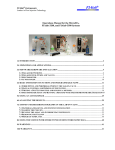
1
Operation
Internal-System
Low Emission Internal-Mix Gel-Coat
For use with Polyester Resin, and Gel-Coat
Maximum fluid working pressure:
20864-05 - 1300 psi. (9 MPa, 90 bar)
21780-01 - 1700 psi. (12 MPa, 117 bar)
22026-01 - 2000 psi. (14 MPa, 138 bar)
Maximum air pressure:
100 psi. (0.7 MPa, 7 bar)
Important Safety Instructions
Read all warnings and instructions in
this manual. Save these instructions.
GC-1317D
Contents
Warnings
Warnings ............................................................................................................................................................
Important Safety Information ..............................................................................................................................
Grounding .......................................................................................................................................................... 3
5
6
Set-up
Set-up Instructions ............................................................................................................................................. Pressure Relief Instructions ...............................................................................................................................
Start-up Instructions ........................................................................................................................................... Shut-down Instructions ....................................................................................................................................... Parts ...................................................................................................................................................................
Assembly Drawings ............................................................................................................................................
Sub-Assembly Drawings ....................................................................................................................................
7
19
20
22
23
N/A
24
Maintenance
Maintenance .......................................................................................................................................................
29
Technical Data
Technical Data ..................................................................................................................................................
Notes ...................................................................................................................................... Graco Ohio Standard Warranty .........................................................................................................
Graco Ohio Information ............................................................................................................ 30
31
32
32
N/A = Non Applicable
GC-1317D
Warnings
The following warnings are for the setup, use, grounding, maintenance, and repair of this equipment.
The exclamation point symbol alerts you to a general warning and the hazard symbol refers to procedurespecific risk. Refer back to these warnings. Additional, product-specific warnings may be found throughout the
body of this manual where applicable.
Materials
• SeeChanging
Important
Safety Information - MEKP, Polyester Resins and Gel-Coats and Spraying and Lamination
Operations section of this manual.
Changing Materials
•
When changing materials, flush the equipment
mulWARNING
tiple times to ensure it is thoroughly clean.
•
Always clean
the fluid
inletsuch
strainers
after and
flushing.
Flammable
fumes,
as solvent
paint fumes, in work area can ignite or explode. To help
•
•
•
FIRE AND EXPLOSION HAZARD
prevent fire and explosion:
•
only in well ventilated
area.
Check withUse
yourequipment
material manufacturer
for chemical
•
Eliminate
all
ignition
sources;
such
as
pilot lights, cigarettes, portable electric lamps, and plastic
compatibility.
drop cloths (potential static arc).
• Keep work area free of debris, including solvent, rags and gasoline.
Most materials use ISO on the A side, but some use
• Do not plug or unplug power cords, or turn power or light switches on or off when flammable
ISO on thefumes
B side.
are present.
• Ground all equipment in the work area. See Grounding instructions.
Epoxies• often
amines onhoses.
the B (hardener)
Usehave
only grounded
side. Polyureas
oftenfirmly
havetoamines
on the B (resin)
• Hold gun
side of grounded
pail when triggering into pail.
side. • If there is static sparking or you feel a shock, stop operation immediately. Do not use
equipment until you identify and correct the problem.
• Keep a working fire extinguisher in the work area.
• See additional information on MEKP in the MEKP Section of this manual.
SplatterPERSONAL
Hazard
PROTECTIVE EQUIPMENT
This sectionYou
is used
RAM plates
which
could get
pushed
out of servicing,
the drumsorofwhen
sealant.
mustwith
wearsome
appropriate
protective
equipment
when
operating,
in the
operating area of the equipment to help protect you from serious injury, including eye injury,
inhalation of toxic fumes, burns, and hearing loss. This equipment includes but is not limited to:
• Protective eyewear
• Clothing and respirator as recommended by the fluid and solvent manufacturer
• Gloves
• Hearing protection
WARNING
SPLATTER HAZARD
Hot
or toxic
fluid
can
causeHAZARD
serious injury if splashed in the eyes or on skin. During blow off of platen,
TOXIC
FLUID
OR
FUMES
splatter
mayoroccur.
Toxic fluids
fumes can cause serious injury or death if splashed in the eyes or on skin, inhaled, or
• swallowed.
Use minimum air pressure when removing platen from drum.
•
•
Read MSDS’s to know the specific hazards of the fluids you are using.
Store hazardous fluid in approved containers, and dispose of it according to applicable
guidelines.
Always wear impervious gloves when spraying or cleaning equipment.
•
Burn Hazard
For equipment used with heated material.
WARNING
GC-1317D
BURN HAZARD - Hot Surfaces
Equipment surfaces and fluid that’s heated can become very hot during operation. To avoid severe burns:
• Do not touch hot fluid or equipment.
• Wait until equipment/fluid has cooled completely.
Skin Injection Hazard
Use with high pressure equipment, generally equipment with pressure rating of 900 psi or higher. There
sions of this section. 1) manual guns, 2) UL-1450 compliant equipment 3) automatic guns,/dispense val
Warnings
tion valves, 4) heated hoses. Since the text contains mostly “Do not” statements, the symbols have lines
them.
WARNING
WARNING
SKIN
HAZARD
SKININJECTION
INJECTION
HAZARD - Basic
High-pressure fluid from gun, hose leaks, or ruptured components will pierce skin. This may look
High-pressure fluid from gun, hose leaks, or ruptured components will pierce skin. This may l
like just a cut, but it is a serious injury that can result in amputation. Get immediate surgical
a
cut, but it is a serious injury that can result in amputation. Get immediate surgical treatm
treatment.
•
point
gun
at anyone
at of
any
• DoDo
notnot
point
gun at
anyone
or at anyorpart
thepart
body.of the body.
•• DoDo
notnot
put put
youryour
hand hand
over the
dispense
outlet. tip.
over
the spray
•• DoDo
notnot
stopstop
or deflect
leaks with
yourwith
hand,
body,
glove,body,
or rag.glove, or rag.
or deflect
leaks
your
hand,
•• Engage
trigger
lock
when
not
spraying.
Do not spray without tip guard and trigger guard installed.
•• Follow
Pressure
Relief
Procedure
in spraying.
this manual, when you stop spraying and before cleaning,
Engage
trigger
lock
when not
checking, or servicing equipment.
•
Follow Pressure Relief Procedure in this manual, when you stop spraying and before c
checking, or servicing equipment.
MOVING PARTS HAZARD
SKIN
Use with
UL1450
Compliance
Moving INJECTION
parts can pinchHAZARD
or amputate- fingers
and other
body parts.
not aim
gun at,parts.
or spray any person or animal.
•DoKeep
clearthe
of moving
•• DoKeep
not operate
equipment
with
protective
covers
hands and other
body
partsguards
awayor
from
theremoved.
discharge. For example, do not try to sto
• Pressurized
equipment
can
start
without
warning.
Before
checking,
moving, or servicing
any part of the body.
equipment, follow the Pressure Relief Procedure in this manual. Disconnect power or air
• supply.
Always use the nozzle tip guard. Do not spray without nozzle tip guard in place.
•
Use Graco nozzle tips.
•EQUIPMENT
Use caution
when
cleaning and changing nozzle tips. in the case where the nozzle tip clo
MISUSE
HAZARD
spraying,
follow
Pressure
Misuse
can cause
death the
or serious
injury. Relief Procedure for turning off the unit and relieving the
• Dobefore
not operate
the unitthe
when
fatigued
the influence of drugs or alcohol.
removing
nozzle
tiportounder
clean.
Fire and Explosion
Hazard
•• DoDo
notnot
exceed
the
maximum
working
pressure
or
the lowest rated
system
leave the unit energized or undertemperature
pressure rating
whileofunattended.
When
the unit is not
component. See Technical Data in all equipment manuals.
off the unit and follow the Pressure Relief Procedure for turning off the unit.
• Use fluids and solvents that are compatible with equipment wetted parts. See Technical Data
• in High-pressure
sprayRead
is able
inject
toxins
into the body
andFor
cause
serious bodily injury.
all equipment manuals.
fluidto
and
solvent
manufacturer’s
warnings.
complete
Pressurized
Aluminum
Parts
Hazard
that
injection
occurs,
get
immediate
surgical
treatment.
information about your material, request MSDS forms from distributor or retailer.
Check
hoses daily.
and parts
signs worn
of damage.
Replace
any damaged
hoses or parts.
•• Check
equipment
Repair for
or replace
or damaged
parts immediately
with genuine
replacement
parts
only.parts only.
Use with equipment
pressurized
aluminum
Equipment
havereplacement
aluminum parts
thatoraren’t
pres
• manufacturer’s
Thiswith
system
is capable
of producing
XXXX
psi. Usemay
Graco
parts
accesso
Dorated
not alter
or
modify
equipment.
ized - check• with
engineering.
a minimum of XXXX psi.
• Use equipment only for its intended purpose. Call your distributor for information.
•
Always engage the trigger lock when not spraying. Verify the trigger lock is functioning pr
• Route hoses and cables away from traffic areas, sharp edges, moving parts, and hot surfaces.
that
all connections
operating the unit.
•• DoVerify
not kink
or over
bend hoses or are
use secure
hoses to before
pull equipment.
•
Know
how
to
stop
the
unit
and
bleed
pressure
quickly. Be thoroughly familiar with the con
• Keep children and animals away from work area.
•
WARNING
Comply with all applicable safety regulations.
PRESSURIZED ALUMINUM PARTS HAZARD
PRESSURIZED
ALUMINUM PARTS HAZARD
Do not use 1,1,1-trichloroethane, methylene chloride, other halogenated hydrocarbon solvents or fluids
Do
not use
methylene
other
containing
such1,1,1-trichloroethane,
solvents in pressurized aluminum
equipment.chloride,
Such use can
causehalogenated
serious chemical hydrocarbon solvents or fluid
reaction and equipment
rupture, and
in death, serious
injury, and
property damage.
containing
such solvents
in result
pressurized
aluminum
equipment.
Such use can cause serious chemical
reaction and equipment rupture, and result in death, serious injury, and property damage.
Plastic Parts Cleaning Solvent Hazard
GC-1317D
Created for CEDs Texture Sprayer. May have use with other waterbase application equipment with plastic parts th
can be damaged by certain solvents.
Important Safety Information
Methyl Ethyl Ketone Peroxide (MEKP)
MEKP is among the more hazardous materials
found in commercial channels. Proper handling
of the “unstable (reactive)” chemicals presents a
definite challenge to the plastics industry. The
highly reactive property which makes MEKP
valuable to the plastics industry in producing the
curing reaction of polyester resins and gel-coats
also produces the hazards which require great care
and caution in its storage, transportation, handling,
processing and disposal.
Workers must be thoroughly informed of the hazards
that may result from improper handling of MEKP,
especially in regards to contamination and heat.
They must be thoroughly instructed regarding the
proper action to be taken in the storage, use and
disposal of MEKP and other hazardous materials
used in the laminating operation.
MEKP is flammable and potentially explosive,
as well as potentially damaging to the eyes and
skin.
Read material manufacturer’s warnings and
material MSDS to know specific hazards and
precautions related to MEKP.
Contaminated MEKP can become explosive.
Prevent contamination of MEKP with other materials, which includes, but is not limited to polyester
overspray, polymerization accelerators and promoters, and non-stainless metals. Even small amounts
of contaminates can make MEKP explosive. This reaction may start slowly, and gradually build-up heat,
which can accelerate until fire or an explosion result.
This process can take from seconds to days.
Heat applied to MEKP, or heat build-up from contamination reactions can cause it to reach what is
called its Self-Accelerating Decompisition Temperature (SADT), which can cause fire or explosion.
Spills should be promptly removed, so no residues
remain. Spillage can heat up to the point of selfignition. Dispose in accordance with manufacture’s
recommendation.
Store MEKP in a cool, dry and well-ventilated area
in the original containers away from direct sunlight
and away from other chemicals. It is strongly recommended that the storage temperature remain below
86° F (30° C). Heat will increase the potential for explosive decomposition. Refer to NFPA 432.
Keep MEKP away from heat, sparks and open
flames.
GC-1317D
Current catalysts are premixed and do not require
any diluents. GlasCraft strongly recommends that diluents not be used. Diluants add to the possibility of contaminates entering the catalyst system. Never dilute
MEKP with acetone or any solvent since this can produce an extremely shock-sensitive compound which
can explode.
Use only original equipment or equivalent parts
from GlasCraft in the catalyst system (i.e.: hoses, fittings, etc.) because a hazardous chemical reaction
Spraying
materials containing isocyanates creates
may result between substituted parts and MEKP.
potentially
mists,
vapors,
and atomized
To preventharmful
contact with
MEKP,
appropriate
personalparticulates.
protective equipment, including chemically impermeable gloves, boots, aprons and goggles are required
Read
material
manufacturer’s
for everyone
in the
work area. warnings and material
MSDS to know specific hazards and precautions
related to isocyanates.
Isocyanate Conditions
•
•
•
•
Polyester Resins and Gel-Coats
Prevent inhalation of isocyanate mists, vapors, and
atomized particulates by providing sufficient ventilation in the work area. If sufficient ventilation is not
available, a supplied-air respirator is required for
Sprayinginmaterials
containing
everyone
the work
area. polyester resin and
gel-coats creates potentially harmful mist, vapors and
atomized
particulates.
Prevent
inhalationappropriate
by providing perTo
prevent
contact with
isocyanates,
sufficient
ventilation
and the use
of respirators
in the
sonal
protective
equipment,
including
chemically
work area.
impermeable
gloves, boots, aprons, and goggles, is
Read
the material
manufacturer’s
and maalso
required
for everyone
in the warnings
work area.
terial MSDS to know specific hazards and precautions
related to polyester resins and gel-coats.
To prevent contact with polyester resins and gelcoats, appropriate personal protective equipment,
including chemically impermeable gloves, boots,
aprons and goggles are required for everyone in the
work area.
•
•
K
B
Material Self-ignition
To
we
an
Some materials may become self-igniting if applied
too
thickly. Read
manufacturer’s
warnings
Spraying
and material
Lamination
Operations
and material MSDS.
Fo
B
Moisture Sensitivity of
Remove all accumulations of overspray, FRP sandIsocyanites
ings, etc. from the building as they occur. If this waste
is allowed to
build are
up, spillage
of used
catalyst
more
likely
Isocyanites
(ISO)
catalysts
in istwo
component
to
start
a
fire.
foam and polyurea coatings. ISO will react with moisture
If cleaning
solvents
are required,
read material
(such
as humidity)
to form
small, hard,
abrasive crystals,
manufacture’s
warnings
and
material
MSDS
to know a film
which become suspended in the fluid.
Eventually
specific hazards and precautions. (GlasCraft recomwill form on the surface and the ISO will begin to gel,
mends that clean-up solvents be nonflammable.)
increasing in viscosity. If used, this partially cured ISO
will reduce performance and the life of all wetted parts.
GlasCraft recommends that you consult OSHA
The amount of film formation and rate of crystalliSections 1910.94, 1910.106, 1910.107 and NFPA
zation varies depending on the blend of ISO, the
No. 33, Chapter 16,17, and NFPA No. 91 for further
humidity, and the temperature.
guidance.
To prevent exposing ISO to moisture:
Som
abo
if ag
circ
Some
materials may become self-igniting if applied
Grounding
too thickly. Read material manufacturer’s warnings
and material MSDS.
Moisture Sensitivity of
Isocyanites
This equipment needs to be grounded.
Isocyanites (ISO) are catalysts used in two component
Ground
dispense
gun through
to anmoisture
foam
andthe
polyurea
coatings.
ISOconnection
will react with
GlasCraft
approved
grounded
fluid
supply
hose.
(such as humidity) to form small, hard, abrasive crystals,
which become suspended in the fluid. Eventually a film
Check
localsurface
electrical
code
related
manuals
will
formyour
on the
and
theand
ISO
will begin
to gel,
for
detailed
grounding
instructions
of
all
equipment
in ISO
increasing in viscosity. If used, this partially cured
the
work
area.
will reduce performance and the life of all wetted parts.
NOTICE
To prevent cross-contamination of the equipment’s
wetted parts, never interchange component A (isocyanate) and component B (resin) parts.
Foam Resins with 245 fa
Blowing Agents
Some foam blowing agents will froth at temperatures
above 90°F (33°C) when not under pressure, especially
if agitated. To reduce frothing, minimize preheating in a
circulation system.
The amount of film formation and rate of crystallization varies depending on the blend of ISO, the
A grounding wire and clamp are provided,
humidity, and the temperature.
assembly p/n 17440-00 with all FRP equipment.
To prevent exposing ISO to moisture:
Notice
The Mast must be secured in the retracted position, and
held secure to prevent rotation before transporting the
Rev. G 6/17/2008
system.
21
GC-1317D
and material
MSDS.
(such
as humidity)
to form small, hard, abrasive crystals,
which become suspended in the fluid. Eventually a film
will form on the surface and the ISO will begin to gel,
increasing in viscosity. If used, this partially cured ISO
willSet-Up
reduce performance and the life of all wetted parts.
Foam Resins with 245 fa
Blowing Agents
Some foam blowing agents will froth at temperatures
Moisture Sensitivity of
above 90°F (33°C) when not under pressure, especially
if agitated. To reduce frothing, minimize preheating in a
Isocyanites
The amount of film formation and rate of crystalliAny mounting option: cart mast and boom, floor
3. Slide catalyst jug bracket over the mast and DO NOT
circulation system.
zation
depending
onused
the
blend
ISO, the
Isocyanites
(ISO)
catalysts
in twoof
component
mount,varies
or wallare
mount
should
be
completely
TIGHTEN.
and
the
temperature.
foam humidity,
and
polyurea
coatings.
ISO
will reactsteps.
with moisture
assembled
before
starting
the following
(such
as
humidity)
to
form
small,
hard,
abrasive
crystals,
To prevent exposing ISO to moisture:
which become suspended in the fluid. Eventually a film
Tools Required:
will form on the surface and the ISO will begin to gel,
1) Standard wrench & socket set
increasing in viscosity. If used, this partially cured ISO
2) Standard hex key set
will reduce performance and the life of all wetted parts.
3) Tape measure or yard stick
Rev. G
6/17/2008
The
amount of film formation and rate of crystalliAll “Required
are standard
zation
varies tools”
depending
on thesizes.
blend of ISO, the
humidity, and the temperature.
21
To prevent exposing ISO to moisture:
1. Attach casters to base plate.
LPA-170
Rev. G 6/17/2008
21
7733-42
7734-10
7486-04
18291-01
20368-00
4. Loosen clamp bolts to expose pump mounting bracket.
Attach pump mounting bracket to the air motor. Use
thread locker on the threads and tighten bolts as tight as
possible.
2. Insert mast into base socket and secure with
supplied bolts.
663
7957-32F
19890-00
GC-1317D
Set-Up
5. a. Stand pump assembly next to the mast and
install the pump mounting bracket.
6. Mount catalyst bottle approximately 26” from the top of
the base plate, to the bottom of the catalyst bracket.
b. Lift to desired height, approximately 36” from the
top of the base to the bottom of the pump mounting bracket. Use 3/4” wrench and tighten as tight
as possible.
7. Attach air manifold p/n 23555-00 to the air motor.
GC-1317D
Set-Up
8. Remove the pump inlet saftey cap and drain the
testing oil into an open container. Attach green
pick-up hose to the pump inlet fitting and tighten.
9. Attach green pick-up hose to the pick-up tube.
9.
FOR INDY GUN INSTALLATION BEGIN
STEPS 10 THRU. 17 .
FOR FORMULA GUN INSTALLATION
BEGIN STEPS 18 THRU. 26.
8.
GC-1317D
Set-Up
Indy Gun Option
14. Attach the (stainless steel p/n 20190-xx) catalyst hose
to the catalyst inlet fitting on the back of the gun.
10. a. Lay all of the hoses out straight.
b. Slide the supplied “black scuff jacket” p/n
FM-494 over the hose assembly and leave it
loose until the hoses are attached to the gun.
15. a. Group the hoses together as shown and wrap
them with tape about every 2 feet.
11. Engage the trigger lock.
b. Start approx. 12 in. back from the gun and tape
the end of the “black scuff jacket” with black
tape. Spread the “black scuff jacket” out so
it fits snug around the hoses and tape the
other end with black tape.
Rotate trigger lock
to stop the trigger
from being activated.
12. Attach the (black p/n 21694-xx) material hose to
the material inlet fitting on the back of the gun.
13. Attach the (yellow p/n 236 or 236-xx) solvent hose
to the inlet fitting on the back of the gun.
10
GC-1317D
Set-Up
Secure the four hoses to
the boom with binding straps
p/n 22546-00.
Route the four hoses between
the two springs.
Secure the four hoses to
the boom with binding straps
p/n 22546-00.
16. Start At This End
Route the four hoses from the
gun through the boom as shown
using binding straps p/n 22546-00
to secure the hoses to the boom.
GC-1317D
11
Isocyanites
Isocyanites (ISO) are catalysts used in two component
foam and polyurea coatings. ISO will react with moisture
(such
as humidity) to form small, hard, abrasive crystals,
Set-Up
which become suspended in the fluid. Eventually a film
willIndy
formDispense
on the surface
Gun and the ISO will begin to gel,
increasing in viscosity. If used, this partially cured ISO
Attach
all hoses andand
tubing
shown.
will17.
reduce
performance
theas
life
of all wetted parts.
if agitated. To reduce frothing, minimize preheating in a
circulation system.
The
offor
film
formation
and
This amount
diagram is
displaying
point
to rate of crystallization
varies ONLY
depending
on the
blend of ISO, the
point hook-up
and DOES
NOT
humidity,
and routing
the temperature.
suggest actual
of hoses and
tubing.
All
hoses
and
tubing
should be
To prevent exposing ISO to moisture:
routed neatly, and free of any moving
components.
MAIN AIR
From Boom
Rev. G 6/17/2008
Fluid Section
21
21179-00
Red Tubing
20190-xx
Catalyst Hose
21694-xx
Material Hose
= Air Lines
= Clear Tubing
= Material Hoses
= Catalyst Hose
12
GC-1317D
Set-Up
Clear Tubing
1/4 in.
Clear Tubing
1/8 in.
Catalyst
Bottle
20260-00
Recirculation Hose
(tape together with green material hose)
Do Not insert the hoses in the material
drum until the system has been flushed
Material
Drum
236 or 236-xx
Solvent hose
Solvent Pot
Clear Tubing
3/8 in.
GAM-268-01
Pick-Up Kit
GC-1317D
13
Set-Up
Formula Gun Option
22. Attach the (yellow p/n 236 or 236-xx) solvent hose to
the solvent inlet fitting on the back of the gun.
18. a. Lay all of the hoses out straight.
b. Slide the supplied “black scuff jacket” p/n
FM-494 over the hose assembly and leave it
loose until the hoses are attached to the gun.
23. Attach the (stainless steel p/n 20190-xx) catalyst hose
to the catalyst inlet fitting on the back of the gun.
19. Push in and rotate the trigger lock to stop the
trigger from being activated.
24. a. Group the hoses together as shown and wrap
them with tape about every 2 feet.
b. Start approx. 12 in. back from the gun and
20. Attach the (black p/n 20195-xx) material hose to
the material inlet fitting on the back of the gun.
tape the end of the “black scuff jacket” with
black tape. Spread the “black scuff jacket” out
so it fits snug around the hoses and tape the
other end with black tape.
21. Attach the (clear p/n 9704-03) trigger air tubing to
the trigger air inlet fitting on the back of the gun.
14
GC-1317D
Set-Up
Secure the four hoses to
the boom with binding straps
p/n 22546-00.
Route the four hoses between
the two springs.
Secure the four hoses to
the boom with binding straps
p/n 22546-00.
25. Start At This End
Route the four hoses from the
gun through the boom as shown
using binding straps p/n 22546-00
to secure the hoses to the boom.
GC-1317D
15
Moisture Sensitivity of
Isocyanites
Set-up
Blowing Agents
Some foam blowing agents will froth at temperatures
above 90°F (33°C) when not under pressure, especially
if agitated. To reduce frothing, minimize preheating in a
circulation system.
From Boom
MAIN AIR
Isocyanites (ISO) are catalysts used in two component
foam
and polyurea
coatings.
Formula
Dispense
Gun ISO will react with moisture
(such as humidity) to form small, hard, abrasive crystals,
26.become
a. Remove
the plug from
thefluid.
side of
the air manifold
which
suspended
in the
Eventually
a film and install
the
regulator
kit
p/n
22632-00.
Be
sure
to
PTFE
tape the threads.
will form on the surface and the ISO will begin to gel,
b.
Attach
all
hoses
and
tubing
as
shown.
increasing in viscosity. If used, this partially cured ISO
c. Connect
materialand
hosethe
(20195-xx)
supplied
will reduce
performance
life of allwith
wetted
parts.
fitting (14626-00).
The
amount
ofisfilm
and rate
of crystalliThis
diagram
for formation
displaying point
to point
zation
varies
depending
onNOT
the suggest
blend of ISO, the
hook-up
ONLY
and DOES
actual routing
of hoses
and tubing. All hoses
humidity,
and the
temperature.
and tubing should be routed neatly, and free
To prevent exposing ISO to moisture:
of any moving components.
Rev. G 6/17/2008
21
9704-03
Clear Tubing
21179-00
Red Tubing
22632-00
236 or 236-xx
Solvent Hose
20195-xx
Material Hose
See
step C
20190-xx
Catalyst Hose
Fluid Section
16
= Air Lines
= Clear Tubing
= Material Hoses
= Catalyst Hose
GC-1317D
Set-Up
Clear Tubing
1/4 in.
Clear Tubing
1/8 in.
Catalyst
Bottle
20260-00
Recirculation Hose
(tape together with green material hose)
Do Not insert the hoses in the material
drum until the system has been flushed
Material
Drum
Solvent Pot
Clear Tubing
3/8 in.
GAM-268-01
Pick-Up Kit
GC-1317D
17
Set-Up
SSP-175 Safety Guard Kit
SSP-175
18
Part
Number
Description
Qty.
SSP-172
SURROUND GUARD
1
SSP-173
LEFT PUMP GUARD
1
SSP-174
ANGLE BRACKET
1
SSP-176
GUARD WINDOW
1
SSP-177
RIGHT PUMP GUARD
1
SSP-178
RIGHT FRONT PUMP GUARD
1
20188-16C
SCREW
17
4
7486-05
FENDER WASHER
7486-13
WASHER
3
7734-06
LOCK WASHER
13
GC-1317D
Pressure Relief Procedure
To relieve fluid and air pressures:
1. Push down Yellow slide valve, P/N 21402-00 to bleed
off air to system.
2. Open P/N 21228-00 on catalyst pump to recirculation
position.
3. Open P/N 21192-00 on bottom of material pump.
GC-1317D
19
WA
Read material manufacturer’s warnings and material
MSDS to know specific hazards and precautions
SKIN INJECTION HAZARD - Basic
related to isocyanates.
Start-Up
The following assumes that all connections are tight.
System Start-Up Instructions
1. Select a clean dry air supply.
2. Attach a 3/8” or larger air hose to the Air Manifold
Inlet. Do not use quick disconnect fittings.
•
•
High-pressure fluid from gun, hose leaks, or
Prevent inhalation
of isocyanate
mists, vapors,
and
a cut,
but
it is INJECTION
a serious
injury
that
can
result
SKIN
HAZARD
- Basic
atomized particulates
providing
sufficient
ventila• Doby
not
point gun
at anyone
or at any par
High-pressure
fluid from
gun, hose le•
tion in the work •area.
sufficient
ventilation
is the
not
DoIf not
put your
hand over
spray tip.
a
cut,
but
it
is
a
serious
injury
that ca
available, a supplied-air
respirator
required
forwith your
• Do not
stop or is
deflect
leaks
ha
•
Do
not
point
gun
at
anyone
or at
Before
turning
on
main
air,
check
all
On/Off
Ball
Valves,
everyone in the •workDo
area.
not
spray
without
tip
guard
and
trigge
making certain all Valves are• in the
position
set over the sp
Do“Off”
not put
yourand
hand
• “Off”Engage
trigger
lock
when
not spraying. •
allTo
regulators
in
their
position.
(Turn
knob
counterDo not stop
or deflect perleaks with
prevent contact with•isocyanates,
appropriate
Follow
Pressure
Relief Procedure in th
clockwise
for OFF or•equipment,
reduced
sonal protective
including
chemically
• pressure
Do
notsetting.)
spray
without tip guard an
or servicing
equipment.
impermeable gloves,checking,
boots,
aprons,
and goggles,
is not sp
•
Engage
trigger
lock when
also required for everyone
in
the
work
area.
•
Follow Pressure
Procedu
INJECTION
-Relief
Use with
UL1
5. Place the mixing SKIN
element
straight
intoHAZARD
theor
front
gun
checking,
servicing
equipmen
K
notgun
aimuser
the gun
at, or spray any person or
housing. (refer toDo
spray
manual)
• Keep
hands
and
other HAZARD
body parts- away
fB
SKIN INJECTION
Use w
Material
Self-ignition
partwith
of the
body.tip and
6. Place the retaining nutany
along
the spray
Do not aim the gun at, or spray any pe
• Always
use the nozzle
guard. Do not
spray tip spacer onto
the gun housing.
(refer totip
spray
•
Keep hands and other body part
gun user manual)•
Use Graco nozzle tips.
any part of the body.
Use caution when cleaning and changin
•
Always use the nozzle tip guard.
7. Push the slide valve tospraying,
the open follow
position.
the Pressure Relief Pro
•
Use
Graco nozzle
tips.
Some materials may become
self-igniting
if applied
before removing the nozzle
tip to clean.
• manufacturer’s
Use caution when
cleaning and
too thickly. Read material
warnings
• Do not leave the unit energized or under
spraying, follow the Pressure Re
and material MSDS.
off the unit and follow the Pressure Reli
before removing the nozzle tip to
• High-pressure spray is able to inject toxin
•
Do not leave the unit energized o
that injection occurs, get immediate sur
off the unit and follow the Pressu
S
• Check hoses and parts for signs of dama
•
High-pressure spray is able to ina
• This system is capable of producing XXX
that injection occurs, get immedi
rated a minimum of XXXX psi.
•
Check hoses and parts for signsc
Isocyanites (ISO)• areAlways
catalysts
used the
in two
component
engage
trigger
lock when not
•
This system is capable of produc
foam
and
polyurea
coatings.
ISO
will
react
with
moisture
•
Verify
that
all
connections
are
secure be
8. Open the air valve p/n 3165 on
the solvent
tank and
rated
a minimum
ofcrystals,
XXXX psi.
(such
as
humidity)
to
form
small,
hard,
abrasive
•
Know
how
to
stop
the
unit
and
bleed pre
adjust the solvent pressure
90 PSI (6.2
bar). the
Open
• to
Always
engage
trigger
lock w
which
become
suspended
in
the
fluid.
Eventually
a
the ball valve p/n 18470-05
onVerify
the solvent
tank.
Next filmare se
•
that
all
connections
will
form
onvalve
the surface
and the
ISO
will
to gel,
open
ball
p/n 23518-00
on the
gun
to begin
verify that
Know
to stop
the ISO
unit and b
increasing in viscosity. If•used,
thishow
partially
cured
•
3. Attach grounding clamp assembly, P/N 17440-00, to
the slave pump.
Attach here
Moisture Sensitivity of
Isocyanites
solvent will flow out of the front of the gun through the
will
reducetip,
performance
and
the life of all wetted parts.
dispense
then close the
valve.
4. Securely attach Clamp, P/N 7749-00, to permanently
grounded rod or pipe.
The amount of film formation and rate of crystalliDo notvaries
exceeddepending
20 PSI (1.4 on
bar)the
onblend
the material
zation
of ISO, the
regulator
until
a
steady
material
flow
has been
humidity, and the temperature.
established.
To prevent exposing ISO to moisture:
Regulator
Valve
Ball valve
18470-00
3165
Rev. G 6/17/2008
14
Attach
14
Here
13193-00
7750-04
7749-00
9654-00
TO SLAVE PUMP
20
GC-1317D
F
B
sonal protective equipment, including chemically
impermeable gloves, boots, aprons, and goggles, is
also required for everyone in the work area.
Keep Components A and
B Separate
Start-Up
Material Self-ignition
SSP-160-01
9a. Pull and rotate Pivot
knob to disengage the catalyst
drive arm.
Some materials may become self-igniting if applied
too thickly. Read material manufacturer’s warnings
and material MSDS.
b. Turn the slave pump
yellow ball valve to the
open position.
Moisture Sensitivity of
Isocyanites
c. Hand prime the pump
b. Once primed, increase the resin PSI until a desired
spray pattern is achieved.
NOTICE
To prevent cross-contamination of the equipment’s
c. Afterwetted
all pressure
adjustments
have been component
completed, aA (isocyparts,
never interchange
finial anate)
spray test
should
be
made.
Spray
a
test
shot
and component B (resin) parts.
sample on a clean piece of paper. The shot should be
approximately five feet in length. You can now check
desired gel times and uniformity of curing.
Foam Resins with 245 fa
Blowing
d. Flush
the gun thoroughlyAgents
with solvent after use.
Some foam blowing agents will froth at temperatures
11. Make
sure
that (33°C)
the resinwhen
pumpnot
recirculation
valve
above
90°F
under pressure,
especially
until a steady stream of catIsocyanites
(ISO) are catalysts used in two component
alyst flows back to the bottle.
foam and polyurea coatings. ISO will react with moisture
(such as humidity) to form small, hard, abrasive crystals,
d. Close
the ball
valve. Hand
which
become
suspended
in the fluid. Eventually a film
stroke
the
pump
until
it develwill form on the surface
and the ISO will begin to gel,
opes 300-400
PSI (21-28
bar). this partially cured ISO
increasing
in viscosity.
If used,
will reduce performance and the life of all wetted parts.
is “off”
and thatTo
thereduce
bypassfrothing,
hose is inminimize
back in the
if agitated.
preheating in a
thecirculation
drum. Adjust
the
resin
pump
regulator
to 20 PSI
system.
(1.4 bar) the pump will start to slowly cycle. Allow the
pump to “load” the cycle rate should slow indicating the
pump is primed. Close the recirculation valve.
The
amount
of the
filmoptional
formation
and rate
of crystalliIf you
are using
Formula
gun set
the
zation
depending
on the
blend
oftrigger
ISO, the
trigger varies
air regulator
to 100 PSI
(7 bar).
The
humidity,
the temperature.
air IS NOTand
to exceed
100 PSI (7 bar).
To prevent exposing ISO to moisture:
Fire and Explosion Hazard
Rev. G 6/17/2008
Fire and Explosion Hazard
Recirculation Valve
Skin Injection Hazard
21
Skin Injection Hazard
Resin
Pump
Regulator
Use with
high
pressure equipment, generally equipmen
10. Trigger the Gun into a container until all the air is
purged from the resin side of the system. It may be
necessary to Hand stroke the Catalyst Pump
several times while the gun is triggered to positively
deliver a steady stream of catalyst. Let go of the
trigger and hand stroke pump again to develop
300-400 PSI (21-28 bar). “STOP”
a. Solvent flush the gun. “STOP”
GC-1317D
sions of this section. 1) manual guns, 2) UL-1450 comp
tion valves, 4) heated hoses. Since the text contains mo
Use with high pressure equipment, generally eq
them.
sions of this section. 1) manual guns, 2) UL-145
tion valves, 4) heated hoses. Since the text cont
them.
WA
W
SKIN INJECTION HAZARD - Basic
High-pressure fluid from gun, hose leaks, or r
a cut, but
it is INJECTION
a serious injury
that can
result
SKIN
HAZARD
- Basic
• Do not point gun at anyone or at any par
High-pressure fluid from gun, hose le
• Do not put your hand over the spray tip.
a cut, but it is a serious injury that ca
Do not exceed 20 PSI
pressure
on the leaks
Material
• (1.4
Do bar)
not stop
or deflect
with your han
•
Do not
point
gun at anyone or at
Regulator until steady
has
been established.
• material
Do not flow
spray
without
tip guard and trigge
•
Do not put your hand over the sp
• Engage trigger lock when not spraying.
•
Do not stop or deflect leaks with
• Follow Pressure Relief Procedure in thi
•
Do not spray without tip guard an
checking, or servicing equipment.
•
Engage trigger lock when
21 not sp
•
Follow
Pressure
Relief
Procedu
SKIN INJECTION HAZARD - Use with
UL1
checking, or servicing equipmen
Do not aim the gun at, or spray any person or
Shut-down
Shut-Down Instructions
Follow pressure Relief Procedure on page 21.
Notice
Due to the different O-Ring materials and lubricants
used in the Guns never submerge or soak any
dispense gun in any type of solvent!
Submerging or soaking any Gun will immediately void
the Gun warranty.
ulates.
Spraying materials containing isocyanates creates
potentially
harmful
mists, vapors,
and atomized
particRead material
manufacturer’s
warnings
and material
ulates.
MSDS to know specific hazards and precautions
related to isocyanates.
Read material manufacturer’s warnings and material
MSDS
know
hazards
Prevent
inhalation
of isocyanate
mists,
vapors, on
and
2. Pushtodown
thespecific
yellow
slide
valve,and
P/Nprecautions
21402-00
the
related
to particulates
isocyanates.
inlet air
to bleed off airbyonproviding
system. sufficient ventilaatomized
tion in the work area. If sufficient ventilation is not
Prevent
inhalation
of isocyanate
mists,
vapors,for
and
available,
a supplied-air
respirator
is required
atomized
by providing sufficient ventilaeveryone particulates
in the work area.
tion in the work area. If sufficient ventilation is not
available,
supplied-air
respirator is required
for perTo preventacontact
with isocyanates,
appropriate
everyone
in the work
area. including chemically
sonal protective
equipment,
impermeable gloves, boots, aprons, and goggles, is
To
prevent
contact
with isocyanates,
peralso
required
for everyone
in the workappropriate
area.
sonal protective equipment, including chemically
impermeable gloves, boots, aprons, and goggles, is
also required for everyone in the work area.
Material Self-ignition
Material
Self-ignition
3. Turn catalyst yellow
ball valve, P/N 21228-00 to Open
1. Activate trigger lock to stop the trigger from being
activated. (Refer to gun manuals if needed.)
/ Recirculation position to dump psi. and close the valve.
Some materials may become self-igniting if applied
too thickly. Read material manufacturer’s warnings
and material MSDS.
Some materials may become self-igniting if applied
too thickly. Read material manufacturer’s warnings
and material MSDS.
Moisture Sensitivity of
Isocyanites
Moisture Sensitivity of
Isocyanites (ISO) are catalysts used in two component
foam and polyurea coatings. ISO will react with moisture
Isocyanites
(such as humidity) to form small, hard, abrasive crystals,
Isocyanites
(ISO)
are catalysts
used
two component
which become
suspended
in the
fluid.inEventually
a film
foam
andon
polyurea
coatings.
ISOISO
will will
react
with to
moisture
will form
the surface
and the
begin
gel,
(such
as humidity)
to
small,
hard,
crystals,
increasing
inshould
viscosity.
If used,
this
partially
cured
ISO
4. Pressure
beform
maintained
on
the abrasive
resin hose.
which
become
suspended
in the life
fluid.
a film
will reduce
performance
and
of Eventually
all wetted parts.
will form on the surface and the ISO will begin to gel,
The
amount
of film formation
and
rate of
crystalliincreasing
viscosity.
used,
partially
cured
If youin
are
using theIfIndy
gunthis
install
the night
plug ISO
zation
varies
depending
on
the
blend
of
ISO,
the
will reduce
performance and the life of all wetted parts.
p/n 23527-00.
humidity, and the temperature.
The amount of film formation and rate of crystalliTo prevent exposing ISO to moisture:
zation varies depending on the blend of ISO, the
Refer to gun
manuals
for service and maintenance.
humidity,
and
the temperature.
Indy Gun
To prevent exposing ISO to moisture:
Rev. G 6/17/2008
Rev. G 6/17/2008
Formula Gun
22
Push in and rotate
trigger lock, p/n:
23774-00.
GC-1317D
•
•
•
•
•
•
K
B
K
B
T
w
a
T
w
a
F
B
F
So
ab
B
if a
So
cir
ab
if a
cir
Parts
Model - Internal Gel-Coat System
Standard Equipment
Part
Number
Description
SSP-160-01
SUPER CATALYST SLAVE PUMP ASSEMBLY
GAM-268-01
MATERIAL PUMP PICK-UP KIT
21694-25
MATERIAL HOSE ASSEMBLY, 25 FT.
17440-00
GROUNDING CLAMP ASSEMBLY
23555-00
AIR MANIFOLD
17798-25
AIR HOSE 25 FT.
20190-00
CATALYST HOSE 25 FT.
21054-01
SOLVENT HOSE 25 FT.
20794-01
SOLVENT TANK
19890-01
MOUNTING CLAMP
18291-01
PORTABLE BASE
663
MAST
20638-00
CASTERS
GC-1317
MANUALS
LPA-165
CATALYST BOTTLE
LPA-170
CATALYST BOTTLE BRACKET
9704-03
TRIGGER AIR TUBING (1/4in. CLEAR, 28ft. FORMULA GUN ONLY)
Pump Options
Part
Number
Description
20864-05
MATERIAL PUMP ASSEMBLY, 11:1 RATIO
21780-01
MATERIAL PUMP ASSEMBLY, 17:1 RATIO
22026-01
MATERIAL PUMP ASSEMBLY, 20:1 RATIO
Material Spray Nozzles
See gun manuals for spray tip options.
GC-1317D
23
Sub-Assembly Drawings
LPA-165 Bottle
Part
Number
Description
Qty.
LPA-167-1
BOTTLE
1
LPA-172
SCREEN
1
LPA-176
CAP
1
21039-00
TUBE ADAPTER
1
21040-00
ELBOW FITTING
1
21044-01
SEAL
1
21045-01
HEX NUT
1
9704-11
TUBING
5
REVISION N
LPA-170 Catalyst Bottle Bracket
REVISION B
24
GC-1317D
Sub-Assembly Drawings
GAM-268-01 Material Pick-Up Kit
Part
Number
Description
Qty.
20394-00
PICK-UP TUBE
1
20395-00
ELBOW FITTING
1
20397-01
MESH FILTER
1
20398-02
MATERIAL HOSE
1
Filter Options
Part
Number
Description
20397-02
100 MESH
20397-03
50 MESH
REVISION D
GC-1317D
25
Sub-Assembly Drawings
23555-00 Air Manifold
Part
Number
Description
Qty.
MPB-208
AIR FILTER
1
14626-01
FITTING
1
1625-23
PIPE PLUG
1
18199-02
AIR REGULATOR
1
18318-02
AIR GAUGE
1
20185-00
CHOPPER DECAL
1
20186-00
MAT’L DECAL
1
20187-00
SOLVENT DECAL
1
20655-04
ELBOW FITTING
1
21179-00
TUBING
10
21402-00
LOCKOUT VALVE
1
3364-03
PIPE TEE
1
6782-03
PIPE TEE
2
7597-04
SWIVEL FITTING
1
8115-03
NIPPLE FITTING
3
REVISION C
20794-01 Solvent Tank
Part
Number
Description
Qty.
ISD-141-3
MINI REGULATOR
1
ISD-142
SOLVENT POT GAUGE
1
RM-856-04
ELBOW FITTING
1
1017-00
FITTING
1
11021-23
PIPE PLUG
1
18470-05
BALL VALVE
1
20324-00
SOLVENT TANK
1
20365-00
RELIEF VALVE
1
20655-04
ELBOW FITTING
1
20720-00
PRESSURE RELIEF VALVE
1
21035-00
PICK-UP STRAINER
1
21044-06
SILICONE O-RING
1
21462-01
FITTING
1
3165
BALL VALVE
1
17440-00
GROUNDING CLAMP ASSY.
1
Optional
Part
Number
Description
Qty.
13867-68
EPR O-RING
1
REVISION D
26
GC-1317D
TORQUE TO 35 IN-LB.
21192-00
4342-23
8462-17
RM-850-02
1
14626-00
(2 TOTAL REQ'D)
5
226819
OUTLET
8462-15
(2 TOTAL REQ'D)
UNATTACHED ITEMS INCLUDE: 14626-00, QTY 1 AND
14626-01, QTY 1
1
NOTES: UNLESS OTHERWISE SPECIFIED
DRILL OUT THRU HOLES TO 33/64" AS REQUIRED.
2
3. VIEW "B" SHOWS CORRECT ORIENTATION OF FITTINGS.
1
14626-01
(2 TOTAL REQ'D)
GC-1317D
4. INCLUDE HEATER OPERATOR'S MANUAL IN KIT.
5
96/0058/99
4 REQ'D
96/0041/99
4 REQ'D
96/0071/99
4 REQ'D
96/0037/99
4 REQ'D
96/0017/99
4 REQ'D
GCC470
INLET
96/0041/99
4 REQ'D
5
20027-00
8462-15
2X 19891-00
2
(HEAT INSULATOR,167002)
(SUPPLIED WITH HEATER)
(SEE MANUAL 307363
FOR MTG INSTRUCTION)
2X 19892-00
7734-10
4 REQ'D
8155-160C
4 REQ'D
Sub-Assembly Drawings
21460-00 Heater Conversion Kit Assembly
27
Sub-Assembly Drawings
155-160C
REQ'D
734-10
REQ'D
21460-00 Heater Conversion Kit Assembly
(20195-25, PART OF HOSE ASSY)
TO GUN
(20260-00, PART OF TANK ASSY)
BACK TO TANK
OUTLET
D-156-04
FROM PUMP
(MAY BE SHIPPED
DISASSEMBLED)
INLET
Part
Number
D-156-04
RM-850-02
14626-00
Qty
HOSE, ASSY
1
FITTING, PIPE, TEE, 3/8
1
FITTING, 3/8NPT X 3/8 NPS
2
14626-01
FITTING, 3/8NPT X 1/4 NPSM
2
19891-00
CLAMP, PIPE, SET
2
19892-00
PLATE, COVER, CLAMP
2
20027-00
FITTING, ELBOW, 1/2NPTM X 1/2NPTF CP
1
226819
HEATER, VISCON (240 VOLT)
1
21192-00
VALVE, BALL, 2-WAY, 3/8
1
GCC470
PLATE, HEATER, MOUNTING
1
96/0017/99
NUT, HEX, 1/4-20, MS, GR2
4
4342-23
FITTING, ELBOW, 3/8 NPTM X 3/8 NPTF
1
7734-10
WASHER, LOCK, SPRING, 1/2
4
8155-160C
28
Description
SCREW, HXHD, CS, .500-13X5.000ZP
4
8462-15
FITTING, PIPE, NIPPLE, HEX, 1/2 X 3/8 NPT
2
8462-17
FITTING, PIPE, NIPPLE, HEX, 3/8 X 3/8 NPT
1
96/0071/99
NUT, HEX, 1/2-13, MS, GR2
4
96/0037/99
WASHER, LOCK, SPLIT, 1/4, MS
4
96/0041/99
WASHER, FLAT, 1/4, 0.28 X 0.63 X 0.065
8
96/0058/99
SCREW, HHC, 1/4-20 X 1.50, MS, GR5
4
GC-1317D
Moisture Sensitivity of
Isocyanites
Maintenance
Blowing Agents
Some foam blowing agents will froth at temperatures
above 90°F (33°C) when not under pressure, especially
if agitated. To reduce frothing, minimize preheating in a
circulation system.
Isocyanites (ISO) are catalysts used in two component 3. Clean pump lube cup and add fresh pump lube.
foam and polyurea coatings. ISO will react with moisture
(such as humidity) to form small, hard, abrasive crystals,
which become suspended in the fluid. Eventually a film
Before
any maintenance
thisbegin
Dispense
will
formperforming
on the surface
and the ISOonwill
to gel,
Gun - Follow
procedures
on pagecured
19. ISO
increasing
in pressure
viscosity.relief
If used,
this partially
will reduce performance and the life of all wetted parts.
The amount of film formation and rate of crystallization varies depending on the blend of ISO, the
humidity, and the temperature.
See Indy and Formula gun manuals for daily maintenance
To prevent exposing ISO to moisture:
and parts replacement procedures.
1. Clean filter at resin pump. When opening pump relief
valve,Gmake
sure all resin and air is evacuated from surge
Rev.
6/17/2008
21
bottle.
Fluid Filter Assembly
2. Inspect and clean filter on pick-up wand.
Filter
GC-1317D
29
Technical Data
30
Category
Data
Maximum Fluid Working Pressure (20864-05)
1300 psi (9 MPa, 90 bar)
Maximum Fluid Working Pressure (21780-01)
1700 psi (12 MPa, 117 bar)
Maximum Fluid Working Pressure (22026-01)
2000 psi (14 MPa, 138 bar)
Maximum Air Inlet Pressure
100 psi (0.7 MPa, 7 bar)
Typical Flow Rate of Pattern Guns
Refer to gun manual
Maximum Fluid Temperature
100° F (38° C)
A Component (Catalyst) Inlet Size
1/4 in. Tube
B Component (Resin) Inlet Size
1 5/16-12 UN-2A Male
Sound Pressure (20864-05)
84.83 dB(A)
Sound Pressure (21780-01)
85.47 dB(A)
Sound Pressure (22026-01)
84.83 dB(A)
Sound Power, measured per ISO 9614-2 (20864-05)
87.04 dB(A)
Sound Power, measured per ISO 9614-2 (21780-01)
91.66 dB(A)
Sound Power, measured per ISO 9614-2 (22026-01)
87.04 dB(A)
Dimensions
88 L X 32 W X 18 H ( 2235.2 X 812.8 X 457.2 mm)
Weight
215 lb (98 kg)
Wetted Parts
Catalyst- Chemically coated aluminum, stainless steel,
chemically resistant o-rings.
Resin- Carbon steel, carbide, chemically resistant orings.
GC-1317D
Notes
GC-1317D
31
Graco Standard Warranty
Graco warrants all equipment referenced in this document which is manufactured by Graco and bearing its name to be free from
defects in material and workmanship on the date of sale to the original purchaser for use. With the exception of any special,
extended, or limited warranty published by Graco, Graco will, for a period of twelve months from the date of sale, repair or replace
any part of the equipment determined by Graco to be defective. This warranty applies only when the equipment is installed, operated
and maintained in accordance with Graco’s written recommendations.
This warranty does not cover, and Graco shall not be liable for general wear and tear, or any malfunction, damage or wear caused
by faulty installation, misapplication, abrasion, corrosion, inadequate or improper maintenance, negligence, accident, tampering,
or substitution of non-Graco component parts. Nor shall Graco be liable for malfunction, damage or wear caused by the incompatibility of Graco equipment with structures, accessories, equipment or materials not supplied by Graco, or the improper design,
manufacture, installation, operation or maintenance of structures, accessories, equipment or materials not supplied by Graco.
This warranty is conditioned upon the prepaid return of the equipment claimed to be defective to an authorized Graco distributor
for verification of the claimed defect. If the claimed defect is verified, Graco will repair or replace free of charge any defective parts.
The equipment will be returned to the original purchaser transportation prepaid. If inspection of the equipment does not disclose
any defect in material or workmanship, repairs will be made at a reasonable charge, which charges may include the costs of
parts, labor, and transportation.
THIS WARRANTY IS EXCLUSIVE, AND IS IN LIEU OF ANY OTHER WARRANTIES, EXPRESS OR IMPLIED, INCLUDING BUT NOT LIMITED
TO WARRANTY OF MERCHANTABILITY OR WARRANTY OF FITNESS FOR A PARTICULAR PURPOSE.
Graco’s sole obligation and buyer’s sole remedy for any breach of warranty shall be as set forth above. The buyer agrees that no other remedy
(including, but not limited to, incidental or consequential damages for lost profits, lost sales, injury to person or property, or any other incidental
or consequential loss) shall be available. Any action for breach of warranty must be brought within two (2) years of the date of sale.
GRACO MAKES NO WARRANTY, AND DISCLAIMS ALL IMPLIED WARRANTIES OF MERCHANTABILITY AND FITNESS FOR A PARTICULAR
PURPOSE, IN CONNECTION WITH ACCESSORIES, EQUIPMENT, MATERIALS OR COMPONENTS SOLD BUT NOT MANUFACTURED
BY GRACO. These items sold, but not manufactured by Graco (such as electric motors, switches, hose, etc.), are subject to the warranty, if any, of
their manufacturer. Graco will provide purchaser with reasonable assistance in making any claim for breach of these warranties. In no event will
Graco be liable for indirect, incidental, special or consequential damages resulting from Graco supplying equipment hereunder, or the furnishing,
performance, or use of any products or other goods sold hereto, whether due to a breach of contract, breach of warranty, the negligence of Graco,
or otherwise.
FOR GRACO CANADA CUSTOMERS
The Parties acknowledge that they have required that the present document, as well as all documents, notices and legal proceedings entered into,
given or instituted pursuant hereto or relating directly or indirectly hereto, be drawn up in English. Les parties reconnaissent avoir convenu que
la rédaction du présente document sera en Anglais, ainsi que tous documents, avis et procédures judiciaires exécutés, donnés ou intentés, à la
suite de ou en rapport, directement ou indirectement, avec les procédures concernées.
Graco Information
TO PLACE AN ORDER, contact your Graco distributor or call to identify the nearest distributor.
Phone: 1-800-746-1334 or Fax: 1-330-966-3006
All written and visual data contained in this document reflects the latest product information available at the time of
publication. Graco reserves the right to make changes at any time without notice.
This manual contains English. GC-1317
Graco Headquarters: Minneapolis
International Offices: Belgium, China, Japan, Korea
GRACO OHIO INC. 8400 PORT JACKSON AVE NW, NORTH CANTON, OH 44720
Copyright 2008, Graco Ohio Inc. is registered to ISO 9001
www.graco.com
Revised 06/2010