1
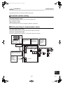
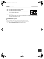
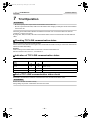
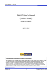
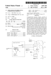
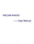
+00DE93419101_01EN.book Page 1 Friday, July 23, 2010 2:22 PM LN INTERFACE Installation Manual Model name: TCB-IFLN642TLE Toshiba +00DE93419101_01EN.book Page 1 Friday, July 23, 2010 2:22 PM Installation Manual LN INTERFACE • Thank you very much for purchasing this TOSHIBA LN interface. • Please read this manual carefully beforehand for proper installation of the LN interface. Contents 1 Precautions for Safety. . . . . . . . . . . . . . . . . . . . . . . . . . . . . . . . . . . . . . . . . . . . . . . . . . 2 2 Introduction . . . . . . . . . . . . . . . . . . . . . . . . . . . . . . . . . . . . . . . . . . . . . . . . . . . . . . . . . . 3 3 Before Installation . . . . . . . . . . . . . . . . . . . . . . . . . . . . . . . . . . . . . . . . . . . . . . . . . . . . . 4 4 Installation . . . . . . . . . . . . . . . . . . . . . . . . . . . . . . . . . . . . . . . . . . . . . . . . . . . . . . . . . . . 4 5 Connection of Power Cables/Communication Cables/Earth Wires . . . . . . . . . . . . . 5 6 Setting. . . . . . . . . . . . . . . . . . . . . . . . . . . . . . . . . . . . . . . . . . . . . . . . . . . . . . . . . . . . . . . 7 7 Trial Operation . . . . . . . . . . . . . . . . . . . . . . . . . . . . . . . . . . . . . . . . . . . . . . . . . . . . . . . . 9 * “ countries. 1-EN “ and “LON” are registered trademarks of Echelon Corporation in United States and other –1– Toshiba XXXXXXX(<SanSerif1>X/X) +00DE93419101_01EN.book Page 2 Friday, July 23, 2010 2:22 PM Installation Manual LN INTERFACE 1 Precautions for Safety • Read these “Precautions for Safety” carefully before installation. • The precautions described below include important items regarding safety. Observe them without fail. Understand the following details (indications and symbols) before reading the body text, and follow the instructions. • After the installation work has been completed, perform a trial operation to check for any problems. Explain how to use and maintain the unit to the customer. • Ask customer to keep this Manual at accessible place for future reference. Indication Meaning of Indication WARNING Text set off in this manner indicates that failure to adhere to the directions in the warning could result in serious bodily harm (*1) or loss of life if the product is handled improperly. CAUTION Text set off in this manner indicates that failure to adhere to the directions in the caution could result in serious bodily injury (*2) or damage (*3) to property if the product is handled improperly. *1: Serious bodily harm indicates loss of eyesight, injury, burns, electric shock, bone fracture, poisoning, and other injuries which leave aftereffect and require hospitalization or long-term treatment as an outpatient. *2: Bodily injury indicates injury, burns, electric shock, and other injuries which do not require hospitalization or longterm treatment as an outpatient. *3: Damage to property indicates damage extending to buildings, household effects, domestic livestock, and pets. Symbols Meaning of Symbols “ " Indicates prohibited items. The actual contents of the prohibition are indicated by a picture or text placed inside or next to the graphic symbol. “ " Indicates compulsory (mandatory) items. The actual contents of the obligation indicated by a picture or text placed inside or next to the graphic symbol. WARNING • Ask an authorized dealer or qualified installation professional to install or reinstall this unit. Inappropriate installation may result in electric shock or fire. • Electrical work must be performed by a qualified electrician in accordance with this installation manual. The work must satisfy all local, national and international regulations. Inappropriate work may result in electric shock or fire. • Be sure to turn off all main power supply switches before starting any electrical work. Failure to do so may result in electric shock. • Do not modify the unit. A fire or an electric shock may occur. CAUTION • Do not install this unit where flammable gas may leak. If gas leaks and accumulates around the unit, it may cause a fire. • Perform wiring correctly in accordance with specified the current capacity. Failure to do so may result in short-circuiting, overheating or fire. • Use predefined cable and connect them certainly. Keep the connecting terminal free from external force. It may cause an exothermic or a fire. EN –2– 2-EN Toshiba +00DE93419101_01EN.book Page 3 Friday, July 23, 2010 2:22 PM Installation Manual LN INTERFACE 2 Introduction Applicable air conditioners TCC-LINK compatible air conditioners Applications/Functions/Features Applications The LN interface is used to control TCC-LINK compatible Toshiba air conditioners by the building control system using LON (Local Operating Network). Functions The LN interface converts signals between TCC-LINK signals for air conditioners and LONWORKS® signals. Features The LN interface enables various settings such as air conditioner operation stop, temperature, operation mode switching by the building control system, as well as monitoring of operating status, room temperature, various settings, etc. One LN interface has a capacity to control indoor units of up to 64 units. A free topology FT-X1 transceiver is used as the LONWORKS® transceiver (also communicatable with FTT-10A). Specifications Name LN interface Model TCB-IFLN642TLE Power supply 220 - 240 VAC, 50/60 Hz Power consumption 10.5 W Number of connectable indoor units 64 units Operating temperature/humidity 0 to 40 °C, 20 to 90% RH Storage temperature -20 to +60 °C (no condensation) Dimensions 66 (H)×246 (W)×193 (D) mm Mass 1.35 kg External View 246 234 6-Ø5.5 mounting holes 246 219 193 193.4 77 193 77 66 63.6 3-EN –3– Toshiba +00DE93419101_01EN.book Page 4 Friday, July 23, 2010 2:22 PM Installation Manual LN INTERFACE 3 Before Installation Check the following package contents. No. Item Quantity 1 LN interface 1 2 Installation Manual 1 3 Screw 4 4 Clamp filter 2 Remarks M4 x 12mm tapping screws Use the following wiring materials to connect the signal lines and power lines. (Locally procured) No. 1 Line For TCC-LINK Description Type 2-core shield wires Wire size 1.25 mm2, 1000m max. 2.00 mm2, 2000m max. Length 2 3 4 For LONWORKS® For power (total length including air conditioner area) Type Twisted pair shield cable (dedicated cable or equivalent) Wire size 0.65 mm × 1P Length Free topology : 500 m max. (total length) Bus topology : 1000 m max. Type Wire size H07 RN-F or 245IEC66 0.75mm2, 50 m max. Installation Installation Method and Orientation There are five installation methods as shown in the figure: surface mount and wall mount. Do not install the unit in any other orientation. Use the attached screws. Good No good REQUIREMENT Do not install the unit in any of the following places. • Humid or wet place • Dusty place • Place exposed to direct sunlight or at a high temperature • Place where there is a TV set or radio within one meter • Place exposed to rain (outdoors, under eaves, etc.) Installation Space and Maintenance Space A side space for connecting through cable inlets and an upper space for maintenance must be reserved before installation. The other sides can be adjacent to surrounding objects. 100mm 100mm EN –4– 4-EN Toshiba +00DE93419101_01EN.book Page 5 Friday, July 23, 2010 2:22 PM Installation Manual LN INTERFACE 5 Connection of Power Cables/ Communication Cables/Earth Wires Connect power cables, communication cables, and earth wires to the specified terminals on the terminal block. Connect the shielded wire of TCC-LINK communication cable to the earth. Connect the shielded wire to FG terminal. Connect the shielded wire of LONWORKS® communication cable to the earth. Connect the shielded wire to FG terminal. Clamp each cable firmly with a cable clamp. U1 FG U2 Air conditioner TCC-LINK LED6 LED5 LED4 LED3 LED2 LED1 LON LONWORKS® system LED8 LED7 SW5 SW1 SW2 SW3 1 2 3 4 SW8 SW4 SW6 L Connect the earth wire to the earth terminal of the chassis. Connect the power supply cable and earth wire to the terminals using ring terminals with insulation sleeve. N Power supply 220 - 240 VAC Length of stripped power cable 35 10 55 10 Length of stripped communication cable 35 10 Attach the provided Clamp filter to the communication cable. • Attach the Clampl filters to the LONWORKS® communication cable and TCC-LINK communication cable as shown below. Fix them to the communication cables with cable ties. • Attach the Clamp filters as close as possible to the LN interface unit. TCC-LINK communication cable LONWORKS® communication cable 5-EN –5– Toshiba +00DE93419101_01EN.book Page 6 Friday, July 23, 2010 2:22 PM Installation Manual LN INTERFACE The following describes a connection example on the system. Terminator resistor setting TCC-LINK terminator resistor The TCC-LINK terminator resistor is set on the air conditioner side. (See “6 Setting” for setting.) LON terminator resistor The LON terminator resistor is set on the upper LONWORKS® system side. Shield grounding of communication cables TCC-LINK communication cable Connect the shielded wire of TCC-LINK communication cable to FG terminal. LONWORKS® communication cable Connect the shielded wire of LONWORKS® communication cable to FG terminal. The TCC-LINK terminator resistor is set on the air conditioner side. Set SW5 to OFF. Connect the shielded wire of TCC-LINK communication cable to the earth. Building management system (by other company) Set (maximum -1) of the indoor unit central control address with SW1 and SW2 in hexadecimal number. TCC-LINK main bus FG U2 U1 TCC-LINK LONWORKS (Other company’s system) SW1 LON Connect the shielded wire of LONWORKS® communication cable to the earth. Connect the shielded wire to FG terminal. U4 U3 SW5 SW2 Outdoor unit U2 U1 U2 U1 Indoor unit U4 U3 U4 U3 Central remote controller U2 U1 U2 U1 Indoor unit U2 U1 Indoor unit Remote controller L Remote controller Power supply 220 - 240 VAC N The LON terminator resistor is set on the upper LONWORKS® system side. Do not set it here. Outdoor unit LN interface EN –6– 6-EN Toshiba +00DE93419101_01EN.book Page 7 Friday, July 23, 2010 2:22 PM Installation Manual LN INTERFACE 6 Setting The following settings are necessary to use the LN interface. TCC-LINK • SW1/SW2 Set the number of indoor units to be connected. Set the maximum of the indoor unit central control address according to the table below. The factory setting is “3F” (64 units connected). REQUIREMENT The set data is read only when the power is turned on. When changing the SW1/SW2 setting, push the reset switch SW6 after setting. (*) Set the indoor unit central control address from 1 to 64 consecutively. This means that the maximum of the central control address equals the number of connected indoor units. However, if an address is omitted, the maximum of the central control address differs from the number of connected indoor units. In this case, set the maximum of the central control address according to the table below. Note: The system works normally when the set value is larger than the maximum. However, it will result in communication loss. Indoor unit central control address and SW1/SW2 setting 7-EN Indoor unit central control address SW1 SW2 Indoor unit central control address SW1 SW2 Indoor unit central control address SW1 SW2 Indoor unit central control address SW1 SW2 1 0 0 17 1 0 33 2 0 49 3 0 2 0 1 18 1 1 34 2 1 50 3 1 3 0 2 19 1 2 35 2 2 51 3 2 4 0 3 20 1 3 36 2 3 52 3 3 5 0 4 21 1 4 37 2 4 53 3 4 6 0 5 22 1 5 38 2 5 54 3 5 7 0 6 23 1 6 39 2 6 55 3 6 8 0 7 24 1 7 40 2 7 56 3 7 9 0 8 25 1 8 41 2 8 57 3 8 10 0 9 26 1 9 42 2 9 58 3 9 11 0 A 27 1 A 43 2 A 59 3 A 12 0 B 28 1 B 44 2 B 60 3 B 13 0 C 29 1 C 45 2 C 61 3 C 14 0 D 30 1 D 46 2 D 62 3 D 15 0 E 31 1 E 47 2 E 63 3 E 16 0 F 32 1 F 48 2 F 64 3 F –7– Toshiba +00DE93419101_01EN.book Page 8 Friday, July 23, 2010 2:22 PM Installation Manual LN INTERFACE • SW3 • SW4 • SW5 Test switch (not used for normal operation, all OFF) Test switch (not used for normal operation) Used to set TCC-LINK terminator resistor. The TCC-LINK terminator resistor is set on the air conditioner side, and is not set here. Set SW5 to “Open”. SW5 TCC-LINK terminator resistor select switch ON 100 ohm • SW6 ON Open Reset switch When changing the setting of the number of connected indoor units with SW1 and SW2, push this reset switch after setting to read the set value. LONWORKS® System LONWORKS® peculiar settings called commissioning and binding are necessary. A specific tool is used for the setting. Ask a professional engineer for this process. • SW8 Service pin for LONWORKS® system Used for Commissioning with the upper LONWORKS® system. EN –8– 8-EN Toshiba +00DE93419101_01EN.book Page 9 Friday, July 23, 2010 2:22 PM Installation Manual LN INTERFACE 7 Trial Operation REQUIREMENT • Be sure to specify each unique central control address of the indoor unit. • Be sure to push the reset switch, SW6 on the LN interface after changing or adding the central control address of the indoor unit. Check the communication status between LN interface and indoor units. It can be checked even when the LONWORKS® system is not running. By using SW1, SW2, and SW3, check the communication status of each connected indoor unit with LED4 and LED5. Checking TCC-LINK communication status Set bit 2 of SW3 to “ON” during normal operation. Set the central control address of the target indoor unit with SW1 and SW2 according to “Indoor unit central control address and SW1/SW2 setting” Example: When checking communication status of indoor unit of central control address 25: Set bit 2 of SW3 to “ON”, SW1 to “1”, and SW2 to “8”. Indication of TCC-LINK communication status LED4 and LED 5 show communication status of the indoor unit selected by SW1 and SW2. TCC-LINK communication status LED5 LED4 Remarks Normal ON OFF Normal ON ON Communication with the indoor unit was established previously, but is disabled currently. No indoor unit OFF ON Communication with the indoor unit has never been established. Invalid indoor unit OFF OFF More indoor units are connected than the LN interface can control. End of TCC-LINK communication status check Re-set SW1 and SW2 to the number of connected indoor units, and set bit2 of SW3 to “OFF”. REQUIREMENT Be sure to re-set SW1 and SW2 correctly. Wrong setting may result in a malfunction when the unit is reset. 9-EN –9– Toshiba +00DE93419101_01EN.book Page 10 Friday, July 23, 2010 2:22 PM Installation Manual LN INTERFACE LED indication during normal operation LED LED1 Normal operation POWER Power indicator Lights while the power is on. LED2 TCC-LINK TCC-LINK communication status indicator Blinks during TCC-LINK communication. LED3 USB – Not used LED4 BUSY TCC-LINK busy indicator Lights temporarily when TCC-LINK is busy (during auto address setting of an air conditioner, etc.). Communication restarts soon. LED5 TEST Test indicator Used in the test mode. LED6 UP-LINK LONWORKS® communication status indicator Blinks during LONWORKS® communication. LED7 RESET Reset indicator Lights when reset operation is performed. LED8 SERVICE LONWORKS® indicator (*) Ask the manufacturer of the upper system for trial operation check of the LONWORKS® system. EN – 10 – 10-EN Toshiba +00DE93419101_01EN.book Page 13 Friday, July 23, 2010 2:22 PM DE93419101 Toshiba