1
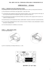
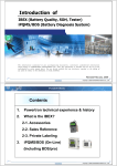
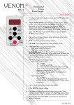
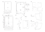
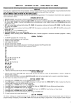
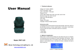
WECAN-RADIO
——User Manual
1
User Manual
1. Introduction
2. Safety Instruction
3. Model definition and function introduction
3.1 WECAN seires model definition
3.2 Transmitter function introduction
3.3 Receiver function introduction
4. Internal structure
4.1 Transmitter internal structure
4.2 Receiver internal structure
5. Exterior connection
6.1 Model
6.2 Model
6.3 Model
6.4 Model
7. system CONFIGURATIONS
7.1
how to set jumper functions
7.2 Receiver RF channel setting
7.3 How to set ID codes
7.4 Frequency Channel Table
8. Receiver installatoin
8.1 Installation attention
8.2 Receiver fixation
8.3 System test
9 Transmitter instruction
10. Failure Remove
11. System parameter
2
1, Introduction
WECAN series wireless remote control system,which is easily used, can be alone applied
in different working condition and industry equipment system, such as automatic controlling. It
can ensure safety requirement of modern industry. Through man y years professional
knowledge and technical experience on Industry communication field,we keep on develop and
make technology first, try to be a leader of wireless remote control field.
The design of WECAN series wireless remote control system, is based on the maximal
safeguard for the user ,and can pass kinds of interfere test of complex condition .
The major features of WECAN600 series are as follow:
*
The system uses advanced microprocessors with highly evolved software that has
redundant error checkin g and correcting capabilities to ensure 100% error -free transmission,
decoding, and control of all output relays.
*
The typical character of WECAN series wireless remote control system includes system
parts self-diagnosing function.the transmitter has com munication check function and know the
situation between transmitter and receiver( for the detailed , see the manual)
* WECAN600 series wireless remote control system, no matter transmitter or Receiver can
be matched according to sepical opeation.(for th e detailed , see the manual)
*
With more than 250 noninterference and different RF channel,it can guarantee many
machines be operated at the same time in the same area.
*
The Degrees of protection of receiver and transmitter can be above IP65 with good
configuration.The transmitter can be used outside completely against the water come in, as the
degrees of protection of water -proof and dust-proof can be reached IP -66.The receiver is
ensure to be used in bad environment as IP65.
*
The life of batteries can be used more with lower transmit power.Use 2 pcs „AA“ batteries
in the trasmitter to make sure at least transmit 100 hours in the smallest distance.
2. Safety Instruction
WECAN600 series wireless remote control system are relatively simple to use, how ever, please
read manual before installation,and operate with correct procedure. It can bring good effect with
correct installtion and use WECAN600 series wireless remote control system.
The following points should be followed when using:
1. Check the transmitter casing and pushbuttons daily.Should any damage be found,the unit
should be removed from service.
2. The transmitter voltage should be checked.If the voltage is low(red status light blinking or
completely off),the batteries should be replaced. If t he transmitter is not used for a long time,
please take out the batteries and keep it safe.
3. The red emergercy stop button should be checked daily to ensure it is in proper working .If
any question, the receiver should be prohitted to use.
4. Turn the power switch ”off” after each use to avoid the mis -operation.
5. Do not use the same RF channel and ID code as any other system in use at the same
facility or test within distance.
6. Never operate a crane or equipment with two transmitters at the same tim e with the same
RF channel and ID code.
3. Model definition and function introduction
3.1 WECAN seires model definition
3
WECAN-6 ** *
Affixal function
The sort of model
Serial number of design
Sign of brand
3.2 Transmitter function introduction
WECAN600S
Shell
①
②
6 one-speed buttons,
Power switch
③
EMS button
④
Down
⑤
Up
⑥ West ⑦
East
⑧
South
North
WECAN610S
2 two-speed buttons + 4 one-speed busttons
Attached drawing and instruction
Shell ②
①
Power switch
③
EMS button ④
Down
⑤
Up ⑥ West
WECAN620S 6 two-speed buttons
Attached drawing and instruction
4
⑦
East
⑧
South
North
Shell
①
②
Power switch
③
EMS button
④
Down
⑤
Up
⑥ West ⑦
East
⑧
South
North
3.3 Receiver function introduction
Front
Back
1、LED Indicator light 2、Label 3、Cable
4、Fastness screws1
5、Fastness screws2 6、Anti-vibration spring 7、Installation screw
4. Internal structure
4.1 Transmitter internal structure
5
1、Transimmitting RF board 2 、IP code dip-switch 3、Battery contact 4、Micro-cpu 5、Power
buton 6、EMS button 7、Double speed 8、Indicator light
4.2 Receiver internal structure
1、Receiving RF board 2、Micro-cpu 3、Position for function 4、Indicator light 5、Output cable
connection 6、Relay 7、AC power input socket 8 、1A fuse 9、5A fuse
5. Exterior connection
5.1 600S,
5.2 610S,
5.3 620S,
6
Note: please install the yellow -green wire into the equipment shell rightly.
7. System configuration
7.1
how to set the jumper.
The receiver has 3 function positions(details on the picture), you can set your system functions
to meet your different requirements, the function settings is below:
1、Special function setting
Join the terminal to the receiver port P3, the relay action for button B is lock form. On the
contrary, the relay action will be action by pressing.
2、Automatic shutoff setting
Join the terminal to the receiver port P2, the main relay will be automatic breaken after 600s by
7
the receiver, if no signal for the open, the receiver won ’t answer any command. On the contrary,
the automatic function of the receiver will be responsive.
3、Masterslave setting
Join the terminal to the receiv er port P1, then it is master receiver, the transmitter will control it
directly. On the contrary, the receiver is slave receiver, you will switch to this receiver by “A”
button.
You can change the port P1 to make one is master or slave. This function is only for 600A, 610A
and 620A.
Note: please shut off the receiver power first and change the port, then it is valid to open the
receiver.
7. 2 Receiver RF channel setting
Both the transmitter and the receiver have a ID code dip -switch, if this is changed, th e RF
channel of the transmitter and the receiver will be changed.
Note:
1、Finishing ID code dip-switch setting, then cut off the equipment, it will be effective after
electricity
2、WECAN series supply more than 256 channels to you, please choose the allo wed channel to
operate. We promise most channels is availability and reliability, but not every channel, if you
find wrong channel, please trip off to use.
7.3
How to set ID codes
WECAN600 series have been set ID code, each system has exclusive code. We can give the
right to modify ID code for special customer, those customer can obey the operational process
to match the transmitter and the receiver at random.
7.4 Frequency Channel Table
8 Receiver installatoin
8 . 1 Installation attention
1,Check and confirm the control traveling crane is normal before installation.
2,Turn off the power.
3,For the receiver position, wherever the crane goes, it should not impact any building extruded.
4,The receiver should be fixed tightly, otherwise it maybe loose and d ropped.
5,It should learn about the crane power and emitter’s function settings (include relay output) to
avoid incorrect connection.
6,The receiver position should be away from motor, transducer and cable at least 3 meters, (see
following picture) to avo id unnecessary interference.
8
Re
c
e
i
v
e
r
>3
M
Mo
t
o
r
>3
M
>3
M
Tr
a
n
s
d
u
c
e
r
M
Cabl
e
7,The receiver should be at the top of the electricity box and then take the output cable into the
electricity box, don’t fix the receiver inside the box. If must be inside the box, then please install
the Antenna outside the box.
re ce i ve r
Right
Wrong
receiver
ca b l e
El e
8.2
El e
box
box
Receiver fixation
Please install the receiver properly to avoid the shake
Installation of the shockproof spring
8. 3 System test
Notice: please sure that all wiring is right and under good protection, all screws are t ight, fix the
cable between the reciever and the crane to avoid the cable be short by the crane shake. Then
open the crane power supply.
1, Test process
First loosen the EMS button,method: rotate the button 1/4 circle clockwise, it will bounce
automatic. Then rotate the left rotory switch to “ON” position, the center indicator will be red,
later turn to blue.
Note 1: when you press the EMS button, you must redo the above operation to open the
receiver.(loosen the EMS, and rotate the switch to ON position)
Note 2: don’t press any button of the transmitter during the power on, or it will make the
9
transmitter into protection.(not sending any signal)
Note 3: after the power on, the transmitter appear red 3 seconds, then turn to blue, or sparkle
one time on red then one time on blue, etc two different condition, details see the manual.
2, Under default state, the control relay of the receiver will disconnect after 10minutes starting
from not any signal. If you don’t need this function, I give a suggestion for you: move the
relevant connecting pieces, then the control relay keep contact until receiving the EMS signal.
Details operation see the manual.
3, Make sure that the contactor is off after pressing the EMS button.
4, Test each function of the relay to meet you r requirement.
5, Operate the emitter farthest to check the signal. If the crane action is discotinuous or blind,
then the operation is very dangerous.
Note: whenever keep your emitter and leave it at proper place. Make sure no one can operate it,
or it will cause very serious aftereffect.
9. Transmitter instruction
1. Install the alkalic battery rightly, suggest to use above 1600AH battery to make the use time
reach 100hours. Don’t use NIH battery, its voltage is only 1.2V.
2. Make sure the EMS button is loose and then turn the emitter power button to ON.
3. Please pay attention to observe the indicator, it will help you to use the remote system.
The explication between the indicator of the transmitter and the corresponding status
LED status
Complement
Explication
Processing method
And then operate
Red light
The transmitter is normal, the
normal
blue
light
is
blink then
voltage & buttons are normal,
Operation normal
close
communication good
bright
And then red blink
The transmitter is low
Please open the
one time after
voltage, please change the
machine after
pressing any buttons
battery on time.
change the battery.
Please check the
And then no action
There is any button in touch
buttons blocked or
Red light light
after pressing any
status, the transmitter pret ect
depressed
and then
3s then
buttons
itself.
open the machine.
warning
Weak signal please ensure
And then normal
Weak signal please
that there is no shielding or
operation blue light is
interferent between the
attention to use.
bright
transmitter and the receiver.
4, Every time you press EMS button,the emitter will send stop signal to the receive r continously,
the signal keeps 3 seconds then stop sending, you must press EMS button to continue. If you
turn the power to “OFF”, then the EMS is invalid.
5, Before close the power of the emitter, please press the red EMS button, then turn the power
button to “OFF”. Don’t close the power directly, it won’t disconnect the relay and keeping on.
6, Button interlock: the emitter has the function, when you press “UP” button, then the emitter
won’t respond “DOWN” command.
7,Change the battery: please change th e battery on time when the voltage is low, you can open
the battery cover, take out them and put new battery.
10. Failure Remove
1
0
If the remote control is not working, please remove the failure according the
following explain.
When the controller can’t wor k normally (pressing the emitter buttons, the receiver has not
action), please check the failure by the following steps:
Item
1.
2.
3.
4.
Failure description
Method
1.Confirm if the battery power is normal.
Emitter LED light
a. Check the battery directions
doesn’t shine,
b. Check the battery box directions
Receiver has no
c. Check the battery capacity
action.
d. Check if the tube is break or uncertain close
2.send to repair
1.Confirm the receiver power input is normal.
2.Check if AC power fuses and DC power fuse melt, if it is
Emitter LED light is
necessary, turn off the power and use the spare fuse.
normal, but Receiver
3.Confirm if the relay output fuse melt, if it is necessary, please
has not action.
use the spare fuse.
4. Send to repair.
1. Confirm if the relay output fuse melt, if it is necessary, please
use the spare fuse
Some actions is not
2.Comfirm if original cable control system works, if so, find the
working
factory to repair.
3.Send to repair.
1.Confirm the emitter battery is abundance
2. Confirm the receiver doesn’t shield by corresponding metal
The Controller
cover or net.
Distance become
3. Confirm surround has not be interfered by strong wireless.
near
4. Confirm no same frequency interfered, which can use to
change the channel.
5. Send to repair.
11. System parameter
WECAN-600 two-speed series Constant technique parameter
Model
Button
Shell
Button mode
Antenna
Battery
Battery life
Frequency
Power
WECAN600S
6
The emitter
WECAN610S
WECAN620S
6
6
ABS enhanced plastics
High reliability two step button
Inside or outside
2pcs AA battery
>100hours
400-460MHz
Less than 10mW
1
1
Model
Input voltage
Wiring
Relay
Respond time
Temperature
Antenna
Enclosure
RF mode
Range
Enclosure
WECAN 600S
The receiver
WECAN 610S
WECAN 620S
DC12V, DC24V, AC85-400V
Pin-insert connection
10A 250V
<100ms
-20-70℃
Outside
IP66
Frequency modulation
100 meter
IP66
Notice: the environment is bad or distance more than 100m, please add the antenna.
Attention
1,Please read the manual before installation and usage
2,Please close the main power when you install and maintain the
remote control to avoid touch electricity.
3,The transmitter is lay at safety place, nobody can push the
button to avoid accident happen.
4,Controlable crane should has mainpower relay, limit switch and other safety facilities.
5,Please stop using when there is lightning strike or disturbance.
non-training person don’t open the machine to avoid break it.
6,This manual is for user reference, please contact us for
details.
7,We hold the right to amend the machine and manual without notice, operation manual is not
confirmed to the machine, please enquiry our company.
1
2