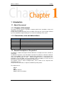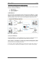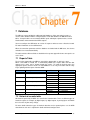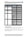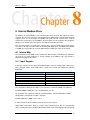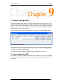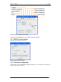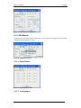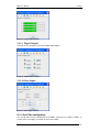
1
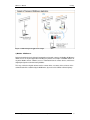
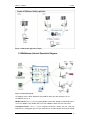
MW User’s Manual
www.exemys.com
Exemys
Rev 2.3.0 – May 2010
1
MW User’s Manual
Exemys
The Exemys products are in permanent evolution to satisfy the needs of our
clients. For this reason, specifications and capabilities are subject to change
without previous notice.
Please find updated information at www.exemys.com
Copyright © Exemys, 2009. All Rights Reserved.
Rev. 2.3.0
www.exemys.com
Rev 2.3.0 – May 2010
2
MW User’s Manual
Exemys
Table of Contents
1 Introduction
1.1
7
About this manual
1.1.1
1.1.2
1.2
7
Purpose of this manual
Conventions, terms and abbreviations
General Description of the product
2 Start-up
7
7
7
12
2.1
Requirements
12
2.2
Installation
12
3 MW Administrator
13
3.1
Introduction
13
3.2
Local Administrator
13
3.2.1
3.2.2
Control buttons
Communication ports
3.2.2.1
3.2.2.2
3.2.2.3
3.2.3
GRD Server
Transparent Server
Modbus Server
14
14
14
Configuration menu
3.2.3.1
3.2.3.2
3.2.3.3
3.2.3.4
3.2.3.5
3.2.3.6
3.3
14
14
15
Authentication
Advanced options
GRD administration
Users and Privileges for Transparent Mode
GRDs’ Modbus Slaves in Modbus Mode
Database
Remote Administrator
3.3.1
3.3.2
21
Authentication
Limitations
21
21
4 Monitor
4.1
22
Connected GRDs
4.1.1
4.1.2
4.1.3
4.2
22
Statistics
4.1.1.1
4.1.1.2
15
15
17
18
19
20
22
Modbus Statistics
Transparent Statistics
IOs Monitor
Configuration
22
23
23
24
Database
24
5 MW with GRDs in Transparent mode
26
5.1
Topology
26
5.2
Configuration
26
5.2.1
5.2.2
5.3
GRD
User
27
28
Final Topology
29
6 MW with GRDs in Modbus mode
30
6.1
Introduction
30
6.2
Topology
30
www.exemys.com
Rev 2.3.0 – May 2010
3
MW User’s Manual
6.3
Exemys
Configuration
6.3.1
6.3.2
6.4
30
GRD
Slaves
31
32
Final Topology
34
7 Database
36
7.1
Reports Table
36
7.2
Historical records table
36
7.3
Commands Table
37
8 Internal Modbus Slave
39
8.1
Internal Map
8.1.1
8.1.2
8.1.3
39
Input Register
Input Status
Coil Status
39
40
40
9 Remote Configuration
9.1
9.1.1
9.1.2
9.1.3
Connecting to the GRD
41
MW Connection monitor
Connection configuration
GRD Monitor
42
42
43
9.1.3.1
9.1.3.2
9.1.3.3
9.1.3.4
9.1.4
9.1.5
Digital Inputs
Analog Inputs
Digital Outputs
Pulses Inputs
43
43
44
44
Serial Port configuration
Reports Configuration
44
45
9.1.5.1
9.1.5.2
9.1.5.3
9.1.5.4
9.1.6
Digital Inputs Reports
Analog Inputs Reports
Pulses Inputs Reports
Digital Outputs Reports
Historical Configuration
9.1.6.1
9.1.6.2
9.1.6.3
9.1.6.4
9.1.7
41
47
Digital Inputs Historical
Analog Inputs Historical
Digital Outputs Historical
Pulses Inputs Historical
Time and date
www.exemys.com
45
45
46
46
47
47
48
48
48
Rev 2.3.0 – May 2010
4
MW User’s Manual
Exemys
Figures
Figure 1 - MW – WEB Example ...............................................................................................8
Figure 2 –MW Transparent application example .......................................................................9
Figure 3 –MW Modbus application example ...........................................................................10
Figure 4 - Functional diagram .................................................................................................10
Figure 5 – Installation error message.......................................................................................12
Figure 6 – Administrator menu distribution .............................................................................13
Figure 7 – GRD port ...............................................................................................................14
Figure 8 – Transparent port .....................................................................................................14
Figure 9 – Modbus port...........................................................................................................14
Figure 10 – Authentication menu ............................................................................................15
Figure 11 – Authentication screen ...........................................................................................15
Figure 12 – Advanced options menu .......................................................................................16
Figure 13 – Advanced options screen ......................................................................................16
Figure 14 – MW-XF service in Windows ................................................................................16
Figure 15 – GRDs menu .........................................................................................................17
Figure 16 – GRDs administration screen .................................................................................17
Figure 17 – Transparent users’ menu.......................................................................................18
Figure 18 – Transparent Users and Permits screen ...................................................................18
Figure 19 – Modbus slaves menu ............................................................................................19
Figure 20 – GRDs Modbus and slaves administration screen ...................................................19
Figure 21 – Database menu .....................................................................................................20
Figure 22 – DB Configuration screen ......................................................................................20
Figure 23 – Remote connection screen ....................................................................................21
Figure 24 – GRDs monitor menu ............................................................................................22
Figure 25 – GRDs monitor screen ...........................................................................................22
Figure 26 – Modbus Monitor ..................................................................................................23
Figure 27 – Transparent Monitor.............................................................................................23
Figure 28 – IOs monitor screen ...............................................................................................24
Figure 29 – Database monitor menu ........................................................................................24
Figure 30 – Database monitor screen.......................................................................................25
Figure 31 – Transparent Topology ..........................................................................................26
Figure 32 – Adding a GRD in Transparent mode.....................................................................27
Figure 33 – Visualization of the added GRD ...........................................................................27
Figure 34 – Adding a user for TM mode..................................................................................28
Figure 35 – Assigning a GRD to a user ...................................................................................28
Figure 36 – Final Transparent topology...................................................................................29
Figure 37 – Modbus Topology ................................................................................................30
Figure 38 – Adding a GRD Modbus ........................................................................................31
Figure 39 – GRD Modbus in the list of valid GRDs.................................................................32
Figure 40 – Window to add slaves to a GRD ...........................................................................32
Figure 41 –Modbus RTU Slaves added to a GRD....................................................................33
Figure 42 –Modbus Slaves added to a GRD ............................................................................34
Figure 43 –Final Modbus topology..........................................................................................35
Figure 44 –Remote configuration ............................................................................................41
Figure 45 –Remote configuration commands...........................................................................42
Figure 46 –MW connection monitor........................................................................................42
Figure 47 –MW connection configuration ...............................................................................43
Figure 48 – GRD Monitor Menu .............................................................................................43
Figure 49 –Digital Inputs Monitor ...........................................................................................43
Figure 50 –Analog Inputs Monitor ..........................................................................................44
Figure 51 –Digital Outputs Monitor ........................................................................................44
Figure 52 - Pulse Inputs Monitor.............................................................................................44
www.exemys.com
Rev 2.3.0 – May 2010
5
MW User’s Manual
Exemys
Figure 53 –Serial Port Configuration.......................................................................................45
Figure 54 –Reports Menu........................................................................................................45
Figure 55 –Digital Inputs Reports Configuration .....................................................................45
Figure 56 –Analog Inputs Reports Configuration ....................................................................46
Figure 57 - Pulses Inputs Reports Configuration......................................................................46
Figure 58 –Digital Outputs Reports Configuration...................................................................46
Figure 59 –Historical Configuration Menu ..............................................................................47
Figure 60 –Digital Inputs Historical Configuration ..................................................................47
Figure 61 –Analog Inputs Historical Configuration .................................................................47
Figure 62 –Digital Outputs Historical Configuration ...............................................................48
Figure 63 - Pulses Inputs Historical Configuration ..................................................................48
Figure 64 –Time and data configuration ..................................................................................49
www.exemys.com
Rev 2.3.0 – May 2010
6
MW User’s Manual
Exemys
1 Introduction
1.1 About this manual
1.1.1 Purpose of this manual
The purpose of this manual is to provide a complete guide for the installation, start-up and
maintenance of the MW-XF.
It begins with a general description of the possibilities offered by the system and then followed
by a more detailed description allowing the user to take full advantage of the system
1.1.2 Conventions, terms and abbreviations
Abbreviation
Description
GPRS
TCP
MW
GRD
Modbus-ASCII
Modbus-RTU
DB
General Packet Radio Services
Transmission Control Protocol
Middleware
GPRS Remote Device
Modbus ASCII format
Modbus RTU format
Database
1.2 General Description of the product
The MW-XF is software that together with the GRD forms a complete tool for the collection of
remote data.
The MW-XF is basically a server with multiple connections that allows the collection of data from
all the existing GRDs in the field and the dumping all the information in several formats to be
accessed in different ways. In a few
words, the MW-XF acts as a concentrator of the
information sent by the GRDs, once the information reaches the MW-XF, it can be accessed
from different media and formats according to the requirements.
The complete system is made of multiple blocks, some of which can be dispensed with
depending on the use.
The present manual describes in depth all the MW-XF operating modes.
The components are:
MW-XF
GRD
MW port redirector
Database SQL (not included)
www.exemys.com
Rev 2.3.0 – May 2010
7
MW User’s Manual
Exemys
Classification according to the user’s software application
There are 3 variants of Middleware as a function of the software used to visualize and obtain
information collected by the Middleware.
1)
2)
3)
WEB Middleware
Transparent Middleware
Modbus Middleware
1) WEB Middleware:
AS the name shows, the final application taking the information from the Middleware, is simply a
web page, previously designed and based on the user’s application. For this purpose the WEB
Middleware registers all the information from remote acquisition and control devices (GRD), into
an SQL-type database, which can be read from any Web application designed to that effect.
Figure 1 - MW – WEB Example
2) Transparent Middleware:
Transparent Middleware is used in applications where a transparent communication tunnel is
needed between the device to be controlled and the original software of the device.
For this purpose, a port redirector is installed in the computer having the device original
software, and takes the information of the original software and sends it to Middleware, which in
turn retransmits to the corresponding remote device.
In this manner, neither the original software nor the remote device is aware of the existence of
the communication link established by the Middleware, by means of GPRS cellular telephony.
www.exemys.com
Rev 2.3.0 – May 2010
8
MW User’s Manual
Exemys
Figure 2 –MW Transparent application example
3) Modbus Middleware:
Designed particularly for the industrial automation and control segment, the Modbus Middleware
allows the use of any final application handling this protocol, for example a SCADA software or
any other Modbus master software, to access information from the remote devices, which were
originally designed to communicate by Modbus.
This way, neither the original software nor the remote device, are aware of the existence of the
communication link established by the Middleware, by means of the GPRS cellular telephony.
www.exemys.com
Rev 2.3.0 – May 2010
9
MW User’s Manual
Exemys
Figure 3 –MW Modbus application example
1.3 Middleware Internal Operation Diagram
Figure 4 - Functional diagram
The diagram shows a block distribution of the MW-XF and its possible alternatives of use.
The MW-XF consists of:
Modbus Server: This is a server accepting Modbus connections through a configurable port. It
can receive Modbus TCP, Modbus RTU over TCP or Modbus ASCII over TCP connections.
Transparent Server: This is a server accepting connections directly from the serial port
Redirector in a configurable port. The port redirector has an authentication mechanism through
www.exemys.com
Rev 2.3.0 – May 2010
10
MW User’s Manual
Exemys
a configurable user and password, once authenticated a virtual serial port in the redirector PC is
opened which is directly linked with a serial port of a determined GRD.
Administrator’s Server: By means of this server it is possible to connect with an administrator
capable of modifying all MW configurations, for example, communication ports, GRD
operational modes, users, passwords, etc.
GRDs’ Server: This is server that accepts connections of GRDs, which when connecting with
the MW are authenticated through an identification number and a password. Through this
channel all data from or to GRDs enter and exit.
DB Client: A client to an SQL Database. When enabled all data from equipments, reports or
historical are dumped.
Internal Modbus slave: This is a Modbus slave which is accessed through the Modbus
connections server with the ID 247. It has the updated values of all inputs and outputs of the
GRD.
www.exemys.com
Rev 2.3.0 – May 2010
11
MW User’s Manual
Exemys
2 Start-up
2.1 Requirements
The minimum necessary requirements to run Middleware are:
•
•
•
2.4 GHz processor or better with at least 512 RAM.
A PC with Windows 2000, Windows XP, Windows 2003 Server (for support for other
platforms please contact [email protected])
The PC must have Java Runtime Environment 1.6 or above (available free from
www.java.com)
2.2 Installation
Insert the CD and execute file MW-XF(Vx.x.x).msi, then indicate the directory where the MW will
be installed and press “Install”, the system will do the rest.
Two components are installed:
•
•
MW-XF Service
MW-XF Administrator
The Service component is the MW itself, this service is running all the time in the computer and
will automatically activate at the moment of installation.
The administrator is simply the configuration tool that has access to the MW service.
If you don’t have the correct Java version installed, an error message will appear during
installation indicating that the installation could not be completed successfully.
Figure 5 – Installation error message
What really happened is that the execution of the MW service failed for not having Java
installed in your computer, if this happens you should install Java’s latest version and enable
the service from the administrator in Advanced options.
www.exemys.com
Rev 2.3.0 – May 2010
12
MW User’s Manual
Exemys
3 MW Administrator
3.1 Introduction
The MW administrator is the interface that allows you to configure the MW
With this tool we may know the status of the service, act on it, add or remove GRDs, users,
monitor the connection status of each one, etc.
The administrator can function locally or in remote form. The local administrator is installed
together with the MW, the remote administrator is a tool you can use in case you need to
remotely access the MW. Both have almost the same functional features, the main difference is
at the moment a session starts, since the remote administrator requires an authentication with
the user name and password before starting to operate.
3.2 Local Administrator
The local administrator is installed together with the MW and it does not require any type of
authentication to be able to enter, but only works from the same computer where the MW is
installed.
To gain access click on the administrator icon
Figure 6 – Administrator menu distribution
www.exemys.com
Rev 2.3.0 – May 2010
13
MW User’s Manual
Exemys
3.2.1 Control buttons
There are 2 buttons, Start and Stop. The Start button starts operating the MW, which means
that is ready to receive the GRD connections, port redirectors and Modbus masters,
additionally, being activated, it connects to the database to store history and the reports.
When the Stop button is pressed it stops the MW operation, all communication ports are closed,
therefore, all existing connections are lost and the configuration options are enabled for the
change of ports.
Keep in mind that the Start and Stop buttons do not stop the service, they only act on the MW.
3.2.2 Communication ports
There are 3 main ports to configure.
3.2.2.1 GRD Server
This is the communications port where the GRDs are connected.
Figure 7 – GRD port
3.2.2.2 Transparent Server
This is the communications port where the port redirectors are connected. For more information
see the Redirector’s help.
Figure 8 – Transparent port
3.2.2.3 Modbus Server
This is the communications port where the Modbus masters are connected to know the status of
inputs and outputs of the GRDs.
Figure 9 – Modbus port
In addition to the entry of the port, it is possible to indicate the Modbus protocol type that the
master uses, they can be:
•
•
•
Modbus TCP
Modbus RTU (over TCP)
Modbus ASCII (over TCP)
www.exemys.com
Rev 2.3.0 – May 2010
14
MW User’s Manual
Exemys
We can configure an Offset. This number goes from 255 to -255 and indicates the offset of the
Modbus slave ID that wants to be accessed. When a query is made the offset is added to the ID
number that enters in a query, this means that if the Offset is equal to 4 and the query is made
to ID 15, it is like the query will be made to slave 19, this happens for all queries.
3.2.3 Configuration menu
The configuration menu has 3 main sections in which it is possible to configure authentication
parameters, GRDs configuration, users and slaves, and other monitor section.
3.2.3.1 Authentication
To gain access to the authentication screen we must go to Start -->Administrator Authentication
Figure 10 – Authentication menu
Through authentication it is possible to restrict the remote access by means of a user and a
password.
Figure 11 – Authentication screen
A user, a password and a confirmation of the password must be entered in the authentication
screen. Once we press the “Save” button the parameters are modified.
The maximum length of the user name and password is 10 characters.
3.2.3.2 Advanced options
To access the advanced options screen we go to Configuration->Advanced.
The Advanced option is activated only for the local Administrator, the remote
Administrator can not access Advanced options
www.exemys.com
Rev 2.3.0 – May 2010
15
MW User’s Manual
Exemys
Figure 12 – Advanced options menu
The advanced options let us act on the MW service, and also allow us to modify the internal
communication ports
Figure 13 – Advanced options screen
The “Start” and “Stop” buttons act directly on the MW service, this means that if the service has
stopped it won’t be possible to access the rest of the configurations and the local administrator
will be seen as deactivated, while communication cannot be established with the remote
administrator.
The same effect you get in the Windows operating system accessing to Settings>Administrative tools-> Services.
Figure 14 – MW-XF service in Windows
Under the stopped service condition the MW does not respond, and does not perform any
control action or connection.
On the other hand, when service has stopped, it is possible to modify the internal
communication ports.
The administration interface port is the one used to connect from the MW administrator
On the other hand we have the internal database port which provides us with the internal
communication between the MW and the database where its entire configuration is stored. This
www.exemys.com
Rev 2.3.0 – May 2010
16
MW User’s Manual
Exemys
database is not visible to the user, but it is possible to determine the communications port, by
choosing any free port between 1 and 65535.
3.2.3.3 GRD administration
To access the GRD administration screen we have to go to Configuration ->GRDs.
Figure 15 – GRDs menu
The GRDs administration screen allows us to add or delete equipment and configure the
operational mode of the serial port of the GRD.
Figure 16 – GRDs administration screen
With the “New GRS” button the options are activated to add a new GRD. Each GRD is identified
with a unique ID and for security reasons there is a possibility of including a password which
must be the same as the configured in the GRD. In a descriptive form it is possible to enter the
telephone number and a minimal description to be able to identify the remote point. We must
indicate the operational mode of the serial port of the GRD. There are 2 possible alternatives:
Transparent or Modbus.
The Transparent mode indicates that the GRD remote equipment is going to work as a serial
port tunnel together with the port Redirector.
www.exemys.com
Rev 2.3.0 – May 2010
17
MW User’s Manual
Exemys
The Modbus mode indicates that the GRD remote equipment has Modbus slaves connected to
its serial communication port, therefore, when a query is made to the slave that this GRD has
connected in its port, the query will be automatically routed to that GRD.
If the GRD ID is not in the list of valid GRDs, no connection of the equipment to the MW is
possible.
If the GRD already exists it is possible to modify the entered values, if the operational mode is
modified the equipment will be disconnected from the MW so changes will become effective
when the equipment is reconnected.
3.2.3.4 Users and Privileges for Transparent Mode
To access the Transparent Users and Privileges screen we must go to Configuration -->Users –
Transparent Serial Port
Figure 17 – Transparent users’ menu
The Transparent Users and Privileges screen allows us to add or delete users and assign
privileges to users for the GRDs of choice.
The GRDs that can be assigned are those configured Transparent mode.
Figure 18 – Transparent Users and Permits screen
The configured user and password are used for the authentication of the port Redirector. When
a Redirector is connected to MW it must indicate the user name and password, from here the
www.exemys.com
Rev 2.3.0 – May 2010
18
MW User’s Manual
Exemys
MW informs to the redirector the GRDs to which that user has access to. Once the GRD to be
accessed is selected, the communication is established.
3.2.3.5 GRDs’ Modbus Slaves in Modbus Mode
To access the screen for the administration of GRDs’ Modbus slaves we have to go to
Configuration->Slave (Modbus Serial)
Figure 19 – Modbus slaves menu
The GRDs’ Modbus slave’s administration screen allows us to add or delete the slaves
associated to each GRD.
Figure 20 – GRDs Modbus and slaves administration screen
The screen shows in the upper part all GRDs that in their operational mode were selected as
Modbus.
www.exemys.com
Rev 2.3.0 – May 2010
19
MW User’s Manual
Exemys
When selecting some of them we can visualize in the lower part the slaves assigned to the
selected GRD.
It is possible to add or delete Modbus slaves to a GRD. A slave number can be assigned to a
unique GRD and not to several of them. Each GRD can have multiple slaves.
On the other hand it is also possible to place the response timeout of the slave connected to the
GRD as well as the GRD’s serial port communication protocol (Modbus-RTU or Modbus-ASCII)
3.2.3.6 Database
To access the database configuration screen it is necessary first to stop the MW pressing the
Stop button in the main screen, then enter in Configuration->Database.
Figure 21 – Database menu
The Database screen makes reference to the SQL/MySQL database where history, reports and
commands are stored.
Figure 22 – DB Configuration screen
Here we can enable the DB, configure it’s IP address, it’s port number, the user and password
the MW will use to connect to the database, the name of the database and finally the type of
database (MS SQL or MySQL).
www.exemys.com
Rev 2.3.0 – May 2010
20
MW User’s Manual
Exemys
Keep in mind that the user and password configured on the MW must have all
reading and writing privileges enabled in the database.
3.3 Remote Administrator
The remote administrator is a separate program that allows access to the MW from any
computer and works like the local administrator, with previous authentication.
3.3.1 Authentication
Authentication is necessary before beginning to operate with the remote administrator, this
means that we must enter a user name and password in order to gain access.
Figure 23 – Remote connection screen
The following parameters must be completed:
Server: The IP address or URL where the server is located.
Port: The administrator's port. This port is totally configurable and we will see this later.
User: User name to be able to access. The user name is configurable and only one is
permitted.
Password: Password to be able to access. The password is configurable and only one is
permitted.
The parameters indicated above are the same as the ones entered in the configuration menu in
the authentication section.
Once all parameters are entered press “Connect”. If the connection is successful it appears
directly in the administrator’s window. If the connection fails a sign will appear indicating the
reason of the failure.
In order for the administrator to be connected, the MW service must be operating.
3.3.2 Limitations
The remote administrator has limitations to act on the service itself. It cannot stop the service or
start it, therefore it is not possible to modify the internal database ports and the remote
configuration ports.
www.exemys.com
Rev 2.3.0 – May 2010
21
MW User’s Manual
Exemys
4 Monitor
4.1 Connected GRDs
To determine the status of the GRDs connection it is possible to go to the monitor screen
through the menu in Monitor ->Connected GRDs.
Figure 24 – GRDs monitor menu
The monitor screen shows the status of the connection of each one of the GRDs, as well as its
operational mode, the IP address from which the GRD is coming from. From here we can also
se the GRDs serial port communication statistics, to monitor the GRD IO’s reported values and
to remotely configure the GRD.
Figure 25 – GRDs monitor screen
In the previous figure we can clearly observe that GRD 654 is connected to the MW, that it’s
serial port is configure to work using Modbus and the remote IP address is 200.49.201.26, while
GRD 22 is disconnected.
4.1.1 Statistics
The statistics make reference to the quantity of information transmitted and received to the
serial port. The information provided by the statistics differs according to how the GRD serial
port’s configuration has been defined.
To have access to the statistics for each GRD press the “Open” button in the statistics column.
4.1.1.1 Modbus Statistics
The Modbus statistics screen is shown below
www.exemys.com
Rev 2.3.0 – May 2010
22
MW User’s Manual
Exemys
Figure 26 – Modbus Monitor
When the GRD is connected the window is visualized as activated, on the contrary if the GRD is
disconnected the window shows grey tones as being deactivated.
The screen shows the quantity of packets sent to the GRD and received from the GRD, those
queries sent to the GRD that have no response are part of the Timeout count.
The Erase button sets the counters to zero.
4.1.1.2 Transparent Statistics
The Transparent Statistics screen is shown below
Figure 27 – Transparent Monitor
When the GRD is connected and the same way a user is connected to the MW pointing to that
GRD the screen is shown as activated.
In the Transparent mode statistics we can find the user’s name and the IP where he is located,
as well as the number of bytes transmitted to the GRD’s serial port and the bytes received from
the GRD’s serial port.
The Erase button sets again the byte counters to zero.
4.1.2 IOs Monitor
The IOs Monitor will show you the reported value of the GRD’s inputs and outputs. Keep in mid
that if you don’t enable IOs reports on the GRD the value you see here won’t be updated.
To have access to the IOs monitor for each GRD press the “Open” button in the Monitor
column.
www.exemys.com
Rev 2.3.0 – May 2010
23
MW User’s Manual
Exemys
Figure 28 – IOs monitor screen
We will see the same screen, no matter want how many inputs and output the GRD has.
The IOs monitor screen has three parts. Digital inputs, Analog inputs and Digital outputs.
If the GRD has fewer inputs the value on the monitor screen will never change.
If the GRD has fewer outputs it will still accept an ON/OFF command and you will see the red
LED changes it state, but this change won’t be reflected on a physical output.
4.1.3 Configuration
The configuration screen allows us to configure the GRD remotely.
To have access to the configuration screen for each GRD press the “Open” button in the
Configuration column.
Read chapter 9 for more details.
4.2 Database
To determine the status of the database we can access the database monitor screen in Monitor>Database
Figure 29 – Database monitor menu
Database monitor indicates the operation of its tables and is shown in the following screen.
www.exemys.com
Rev 2.3.0 – May 2010
24
MW User’s Manual
Exemys
Figure 30 – Database monitor screen
The IP address/URL, port number and database name must coincide with the one entered in
the original configuration, then we find the three tables forming the database for the MW. If
everything works correctly the three must show “Ready”. If this does not happen, verify the IP
address/URL, the connection port, user name and password, verify that the MySQL/SQL
database service is operational and that the user has the read and write privileges to access the
database.
www.exemys.com
Rev 2.3.0 – May 2010
25
MW User’s Manual
Exemys
5 MW with GRDs in Transparent mode
This chapter explains how to configure the MW to make a connection using the Transparent
mode.
In transparent mode it is possible to use the GRD’s serial port for any purpose but always
respecting the operational topology
5.1 Topology
The following figure shows the topology to be used for the system to work correctly
Figure 31 – Transparent Topology
On one side, we have a PC with a serial port Redirector installed, the same is connected to the
MW through the designated port. On the other side, the GRD is connected to the MW in the
corresponding port to the GRDs, if the configuration is correct the data sent through the virtual
serial port of the Redirector will be sent to the GRD’s physical serial port and viceversa.
5.2 Configuration
We make the configuration based on a real example and configure the different parameters
step by step.
See the following example:
User: Pablo
Password: exemys
We want to connect the flow meter connected to the GRD with the GRD ID 268 which is located
in the water well.
GRD ID: 268
Password: pozo
MW data
IP/URL: 190.189.165.16
Transparent server’s port: 41000
www.exemys.com
Rev 2.3.0 – May 2010
26
MW User’s Manual
Exemys
GRD’s server port: 35000
5.2.1 GRD
We go to the GRDs Configuration screen and press “New GRD”. Once this is done, the options
to complete the GRD data are enabled.
Figure 32 – Adding a GRD in Transparent mode
As the GRD’s serial port will work in transparent mode set “Mode of Serial Port” in
“Transparent”. The Telephone and Description options are optional and not necessary.
When we finish loading all the necessary data we press the “Save” button to add the GRD to
the list of valid GRDs.
Remember that the GRD must have configured the same ID number and the same
password than the MW to be able to establish the connection.
Figure 33 – Visualization of the added GRD
www.exemys.com
Rev 2.3.0 – May 2010
27
MW User’s Manual
Exemys
5.2.2 User
To be able to add a user we must go to the Users and Privileges for Transparent Serial screen
and press the button “New User”. Once the button is pressed the fields are enabled to be able
to enter the new user data.
Figure 34 – Adding a user for TM mode
Once data are entered we press “Save” to have the MW store the changes.
As soon as we press the button, the user we just entered will appear at the top of the screen. If
we position the mouse over him, the right side of the screen will show the available GRDs,
which are those configured in transparent mode. By ticking over the GRDs that we want to
assign to this user, it links the user to that GRD.
It is possible to assign multiple GRDs to a user and at the same time assign to multiple users
the same GRD.
It is not necessary to save the assignments, when marking over the desired GRD, they are
automatically stored and linked.
Figure 35 – Assigning a GRD to a user
www.exemys.com
Rev 2.3.0 – May 2010
28
MW User’s Manual
Exemys
5.3 Final Topology
If the previous steps were followed to add a GRD and to add a user, the MW is ready to receive
the corresponding connections.
The only thing left is to configure the port redirector and the GRD so they take the values
indicated at the beginning of the chapter, if this happens and the MW is waiting for connections
the final topology is as follows:
Figure 36 – Final Transparent topology
www.exemys.com
Rev 2.3.0 – May 2010
29
MW User’s Manual
Exemys
6 MW with GRDs in Modbus mode
6.1 Introduction
This chapter explains how to configure the MW accept connections from GRDs using Modbus
on there serial ports.
In the Modbus mode it is possible to use the serial port of the equipment to communicate with
devices connected to it by means of the Modbus protocol but always respecting the operational
topology.
6.2 Topology
The following figure shows the topology that should be used for the system to work correctly.
Figure 37 – Modbus Topology
The basic idea is based on a Modbus master that wants to collect data from multiple slaves, in
this case a SCADA was taken as a model.
On the other side, the slaves are connected to the GRD, each slave has a Modbus ID number
that identifies it in the network.
The SCADA must be connected to the MW to be able to make queries to all slave devices and
the GRD are the link between the slaves and the MW.
The same way, more GRDs with other slaves connected in its RS232 or RS485 serial port can
be added.
The queries begin at SCADA, pass through the MW and are derived to the corresponding GRD
that has the corresponding slave connected in its serial port, the response starts at the slave,
passes through the MW by means of the GRD to arrive finally to the Modbus master
6.3 Configuration
The configuration is made based on a real example and we configure the different parameters
step by step.
www.exemys.com
Rev 2.3.0 – May 2010
30
MW User’s Manual
Exemys
Let’s take the following example:
We have 2 Modbus (RTU) devices connected in port RS485 of the GRD with GRD ID = 10
without a password.
Device 1: Modbus ID 43 (read through port 502)
Device 2: Modbus ID 66 (read through port 503)
We also have one Modbus device (ASCII) in port RS232 of GRD with GRD ID = 13 without
password.
Device 1: Modbus ID 87(read through port 504)
MW data
IP/URL: 190.189.165.15
Modbus port: 502
Num. Ports: 3
GRD port: 35000
6.3.1 GRD
We go to the GRDs Configuration screen and press “New GRD”. This enables the options to
complete the GRD data.
Figure 38 – Adding a GRD Modbus
When pressing the button it is stored in the list of valid GRDs. Set the “Mode of Serial Port” in
“MODBUS”
In the following figure we can visualize the addition of another GRD and in the top part the GRD
previously added.
www.exemys.com
Rev 2.3.0 – May 2010
31
MW User’s Manual
Exemys
Figure 39 – GRD Modbus in the list of valid GRDs
Once both GRDs are incorporated to the list we can assign the corresponding slaves to each
one and also indicate in which variation of Modbus protocol will be used on the GRD’s serial
port.
6.3.2 Slaves
To be able to add slaves to each GRD we must access the Slave – Modbus Serial screen, then
we position the mouse over the GRD in the top part and press button “+Slave”, a window
appears like the one shown below where we enter the slave number connected to the GRD in
its serial port and the TCP port number from where the slave will be read.
Figure 40 – Window to add slaves to a GRD
Once the corresponding slaves and TCP ports have been entered we must select which
variation of Modbus protocol will be used on the GRD’s serial port (Modbus RTU or Modbus
ASCII)
www.exemys.com
Rev 2.3.0 – May 2010
32
MW User’s Manual
Exemys
Figure 41 –Modbus RTU Slaves added to a GRD
As we can see in the previous figure the GRD 10 has 2 Modbus slaves that talk Modbus RTU.
Finally configure the Timeout and then we press the “Save” button for changes to be stored.
The purpose of the Timeout is to keep the system from waiting for a response for an determined
time, this time is expressed in milliseconds, therefore, when a query is sent it is the maximum
waiting time for a response, once this time is due the system discards all responses coming
from that GRD until a new query is received.
Verify that the timeout of the Modbus master is higher than the configured Timeout
for the GRD to avoid missing responses to the queries.
Modbus slaves for the following GRD are added the same way, but different from the previous
case, this one has a Modbus ASCII communication protocol.
www.exemys.com
Rev 2.3.0 – May 2010
33
MW User’s Manual
Exemys
Figure 42 –Modbus Slaves added to a GRD
This way, the two GRDs are configured from the MW side and are functioning according to what
was established in the beginning.
6.4 Final Topology
www.exemys.com
Rev 2.3.0 – May 2010
34
MW User’s Manual
Exemys
Figure 43 –Final Modbus topology
The Modbus TCP master is now connected to port 502 of the MW and the queries begin. When
making a query, for example, to slave 66 the MW knows that this is connected to GRD 10,
therefore, the query will be sent to it in the configured protocol, being in this particular case
Modbus RTU. On the contrary, if the query is made to slave 87 it will be addressed to GRD 13
in Modbus ASCII protocol.
When queries are made take into account the Offset configured in the Modbus
server
www.exemys.com
Rev 2.3.0 – May 2010
35
MW User’s Manual
Exemys
7 Database
The MW can connect to MySQL or Microsoft SQL databases. After connecting it creates a
schema and a database with the configured name. Inside that database the MW will create 3
tables. Using this tables we can know the GRDs’ inputs and outputs reported values, to read
historical data and to command the GRD’s outputs.
You must configure the GRD when to send an IO report or when to create a historical record.
For more information see the GRD manual.
When the connection parameters with the database are loaded and the MW starts, the schema
and tables are created automatically.
The tables with the different fields are detailed and a separate appendix shows some queries to
access them.
7.1 Reports Table
The last values reported by the GRD are stored in the reports table, as well as its status.
When a new GRD is created, this is automatically added to the reports table and from that
moment on its status can be known through this means. To know the desired values the
appropriate queries must be made. For each GRD there is an entry in the table and this entry
keeps updating with the reports from that GRD.
Field
Description
Condition
Possible values
grd_id
state
GRD Id number
Indicates status of connection
Connected
Disconnected
1 to 4000
1
0
i0 a i15
Status of digital inputs
o0 a o15
Status of digital outputs
ON
OFF
ON
1
0
1
an0 to an7
Value of analog inputs
p1 a p2
Value of pulses inputs
date
DATE of last report
OFF
GRD3002 / 4002
GRD3003 / 4003
GRD4002
GRD4003
-
0
0 to 1000
0 to 2000
0 to 1000000000
0 to 1000000000
Ex: 2008-12-30 17:44:50
7.2 Historical records table
All historical reported by all GRDs are stored in the historical table. There are different types of
historical register, for example, by digital inputs, by digital outputs, by analog inputs and within
these last ones by time or by change.
For more details about the types of historical data that can be reported please see the GRD
manual where each one is explained in detail and how to configure them.
www.exemys.com
Rev 2.3.0 – May 2010
36
MW User’s Manual
Exemys
The table containing this information has the following format.
Field
Description
Condition
Possible values
historical_id
grd_id
Number of history
GRD_ID number
-
1 to 4000
register_type
Type of record entered
In digital inputs
8
In digital outputs
9
In analog inputs
11
In pulses inputs
12
timestamp
Date of history
-
Ex: 2008-12-30 17:44:50
address
Number of inputs or
outputs
In digital inputs
1 to 16
In digital outputs
1 to 16
In analog inputs
1 to 8
In pulses inputs
1 to 2
In digital inputs
0 or 1
In digital outputs
0 or 1
In analog inputs of
GRD3002 / 4002
In analog inputs of
GRD3003 / 4003
In pulses inputs of
GRD4002
In pulses inputs of
GRD4003
digital inputs
digital outputs
0 to 1000
Temporary report of
analog inputs
1
Analog input below the
minimum
Analog input between
minimum and
maximum
Analog input over
maximum
pulses inputs
2
value
historical_type
Input/Output value
Historical record type
0 to 2000
0 to 1000000000
0 to 1000000000
NULL
NULL
3
4
NULL
7.3 Commands Table
The commands table is used to act on the digital outputs of the GRD. By writing the parameters
on the database it is possible to activate or deactivate any of the equipment outputs.
The MW is continuously checking if an order has been written, in case it has, it takes it from the
database and acts. If the entered data have errors, the parameters will be eliminated from the
database without taking any action.
www.exemys.com
Rev 2.3.0 – May 2010
37
MW User’s Manual
Exemys
Field
Description
Possible values
grd_id
output_number
state
GRD_ID number
Output number that wants to be modified
Status it should take
1 to 4000
1 to 16
0 (OFF)
1 (ON)
date
Current date
Ex: 2008-12-30 17:44:50
www.exemys.com
Rev 2.3.0 – May 2010
38
MW User’s Manual
Exemys
8 Internal Modbus Slave
The MW has an internal Modbus slave containing the values of inputs and outputs, the values
read from this slave are only those corresponding to the GRD reports and not to the historical
registers, these are not accessible via Modbus. We must take into account that in order to
visualize the current values of the GRD the desired reports must be enabled in the equipment.
We access the internal slave when queries are made to the number 247 slave.
The same way queries are made to the external slaves, they are made to the internal slaves.
The same, in its map has all the values of all analog and digital inputs of all GRDs from GRD ID
1 to 4000. It is also possible to act on the digital outputs modifying its status at any instant.
8.1 Internal Map
The information of each GRD can be visualized in different forms according to the parameter
you want to see. Each GRD has a specific location in the Modbus map, this location is
determined through its ID number.
8.1.1 Input Register
In the input registers we are able to know digital inputs as well as analog inputs, and also the
value of digital outputs. Each GRD covers a total of 16 records that contain the following
information
RECORD NUMBER
Record 1 to 8
Record 9
Record 10
Record 11 to 14
Record 15
Record 16
Information
Analog 1 to 8
Digital inputs
Digital outputs
Pulses inputs 1 to 2
Reserved
State
The calculation to determine the address of a register for a determined GRD is the following:
Record X=30000 + (GRD_ID-1)*16 + Record Number (1 to 16)
As an example let’s suppose we want to read analog input 3 from the GRD with the ID=87.
Analog input 3 corresponds to record 3, therefore
Record 3(GRD 87) = 30000 + (87-1)*16 + 3
In order to know the desired value we have to access record 31379
Digital inputs and outputs group in a single record containing in its bits the corresponding
values, knowing that input 1 of GRD corresponds to bit 0 of the record and input 16 corresponds
www.exemys.com
Rev 2.3.0 – May 2010
39
MW User’s Manual
Exemys
to bit 15 of the record we can determine each one. The outputs in the records are located the
same way.
To know if a GRD is connected to the MW you can check bit 0 on the 16th register. If it’s 1 it’s
saying that the GRD is connected to the MW.
GRD4002 and GRD4003's counter inputs can be read on registers 11 to 14. Each one uses 2
registers to store the count value from 0 to 1000000000. The first register has the most
significative word, the second one has the least significative word.
8.1.2 Input Status
In the input status we know the status of digital inputs of all GRDs.
Each GRD occupies 16 positions and the calculation to read the value of one of the inputs is the
following:
Input X = 10000 + (GRD_ID-1)*16 + Input number (1 to 16)
For example, if we want to know the value of input 8 of GRD having ID = 6 the calculation is as
follows:
Input 8 (GRD6) = 10000 + (6-1)*16 + 8
It’s equivalent to Modbus address 10088
8.1.3 Coil Status
In the coil status records we visualize the digital outputs of the equipment.
To determine the address of outputs for each GRD we calculate.
Output X = (GRD_ID-1)*16 + Output number (1 to 16)
For example, if we want to access output 4 of GRD with ID=45 the calculation is the following:
Output 4 (GRD 45) = (45-1)*16 + 4 = 708
It is equivalent to Modbus address 708 of the coil status.
If we write over these records the output status is modified, this means that we can modify the
status of outputs from a GRD from the Modbus internal slave.
www.exemys.com
Rev 2.3.0 – May 2010
40
MW User’s Manual
Exemys
9 Remote Configuration
Remote configuration allows changing the GRD configuration without having to go to the site
where the GRD is installed. Take into account that the GRD must be connected to the MW to be
able to use the remote configuration. If the GRD is not connected to the MW user the GRD
configurator software or read the GRD user’s manual to know how to configure the GRD by
SMS to establish a connection to the MW.
To access to the remote configuration click on the “Open” button on the Configuration column.
Figure 44 –Remote configuration
The main difference between configuring the GRD through the Remote Configuration and doing
it through the GRD Configurator software is that, using the Remote Configuration, the
parameters values must be read manually.
To know further about the GRD configuration please read the GRD user’s manual.
9.1 Connecting to the GRD
If the GRD is connected to the MW the first button will be enabled. If we pressed it you will GRD
the basic GRD information values and will be ready to start reading an writing the rest of the
configuration.
www.exemys.com
Rev 2.3.0 – May 2010
41
MW User’s Manual
Exemys
Figure 45 –Remote configuration commands
If you are using a GRD with no IOs some buttons may not be enabled.
9.1.1 MW Connection monitor
From here we can get the signal level.
Figure 46 –MW connection monitor
9.1.2 Connection configuration
Here we can see the connections configured parameters. It’s only possible to change the
Inactivity Time and the Retry Time.
www.exemys.com
Rev 2.3.0 – May 2010
42
MW User’s Manual
Exemys
Figure 47 –MW connection configuration
9.1.3 GRD Monitor
On this screens you can read the instant value of each inputs and output. Press the button
“Update” to get and refresh the values.
Figure 48 – GRD Monitor Menu
9.1.3.1 Digital Inputs
Figure 49 –Digital Inputs Monitor
9.1.3.2 Analog Inputs
www.exemys.com
Rev 2.3.0 – May 2010
43
MW User’s Manual
Exemys
Figure 50 –Analog Inputs Monitor
9.1.3.3 Digital Outputs
Here you can also change the value of the GRDs digital outputs.
Figure 51 –Digital Outputs Monitor
9.1.3.4 Pulses Inputs
Figure 52 - Pulse Inputs Monitor
9.1.4 Serial Port configuration
You can edit from here the configuration of the GRD’s serial port. Press buttons “Update” to
read the values and “Apply” to transmit de values to the GRD.
www.exemys.com
Rev 2.3.0 – May 2010
44
MW User’s Manual
Exemys
Figure 53 –Serial Port Configuration
9.1.5 Reports Configuration
From here you can configure when the GRD is going to report the values of its inputs and
outputs. Press “Update” to read the values and “Apply” to transmit de values to the GRD.
Figure 54 –Reports Menu
9.1.5.1 Digital Inputs Reports
Figure 55 –Digital Inputs Reports Configuration
9.1.5.2 Analog Inputs Reports
www.exemys.com
Rev 2.3.0 – May 2010
45
MW User’s Manual
Exemys
Figure 56 –Analog Inputs Reports Configuration
9.1.5.3 Pulses Inputs Reports
Figure 57 - Pulses Inputs Reports Configuration
9.1.5.4 Digital Outputs Reports
Figure 58 –Digital Outputs Reports Configuration
www.exemys.com
Rev 2.3.0 – May 2010
46
MW User’s Manual
Exemys
9.1.6 Historical Configuration
From here you can configure when the GRD is going to create historical records. Press
“Update” to read the values and “Apply” to transmit de values to the GRD.
Figure 59 –Historical Configuration Menu
9.1.6.1 Digital Inputs Historical
Figure 60 –Digital Inputs Historical Configuration
9.1.6.2 Analog Inputs Historical
You will find two tabs, one for Historical By Alarm and the other for Historical By Time.
Figure 61 –Analog Inputs Historical Configuration
www.exemys.com
Rev 2.3.0 – May 2010
47
MW User’s Manual
Exemys
9.1.6.3 Digital Outputs Historical
Figure 62 –Digital Outputs Historical Configuration
9.1.6.4 Pulses Inputs Historical
Figure 63 - Pulses Inputs Historical Configuration
9.1.7 Time and date
From here you can configure the GRD’s date and time. The date will be used to create de
historical records. If you press the “Current Date” button your computers time and date will read.
Press “Update” to read the values and “Apply” to transmit de values to the GRD.
www.exemys.com
Rev 2.3.0 – May 2010
48
MW User’s Manual
Exemys
Figure 64 –Time and data configuration
www.exemys.com
Rev 2.3.0 – May 2010
49