1
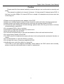
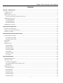
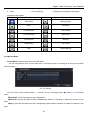
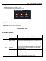
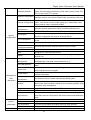
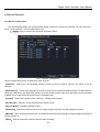
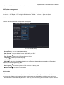
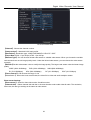
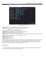
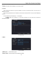
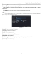
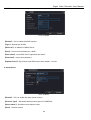
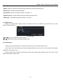
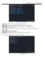
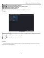
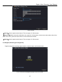
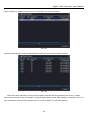
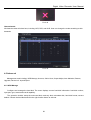
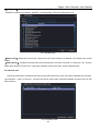
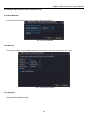
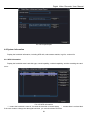
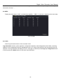
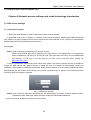
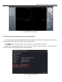
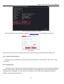
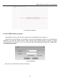
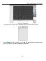
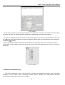
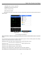
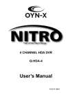
H.264 Digital Video Recorder User Manual For H.264 4ch/ 8ch/16ch/32ch Digital Video Recorder All rights reserved Version 1.1 ADVICES Design and description of this product are subject to change or renewal without notice Digital Video Recorder User Manual Caution Please read this User manual carefully to ensure that you can use the device correctly and safely This manual is suitable for 4 channel, 8 channel, 16 channel and 32 channel series DVR. In this book, we take 200fps 16 channel DVR as a sample. All examples and pictures used are conforming to it. Please use the appropriate power adapter for the DVR Please use individual power instead of share electrical outlets with other electrical equipment. Please choose high quality hard disk which could meet the working demand of DVR. To protect the main chipset from thunder damage, please make sure the ground wire is correctly connected before using DVR. Do not expose DVR to rain or moisture. Avoid direct sunlight and stay away from heat source. Keep all liquid away from the DVR. Do not touch the power plug or case with wet hands as this could result electric shock. Do not put heavy objects on the DVR The DVR cannot be installed at the place with dust. And avoid potential mechanical vibration or impact. Do not disassemble or repair the DVR by yourself. Do not open the cover or insert any objects into DVR. Handle with care; avoid the collision or strong fall. If the DVR run into hard objects accidentally, which leads to the DVR cannot work normally, please contact the authorized dealer to repair or replacement. 2 Digital Video Recorder User Manual Contents CHAPTER 1- INTRODUCTION........................................................................................................................................................ 5 1.1 DVR INTRODUCTION................................................................................................................................................................ 5 1.2 MAIN FEATURES ..................................................................................................................................................................... 5 1.3 FRONT PANEL INSTRUCTIONS ...................................................................................................................................................... 6 1.3.1 Front panel button operation function list. ................................................................................................................. 7 1.4 REAL PANEL INSTRUCTIONS ........................................................................................................................................................ 8 1.4.1 4CH DVR panel ........................................................................................................................................................... 8 1.4.2 8CH DVR panel ........................................................................................................................................................... 8 1.4.3 16CH DVR panel ......................................................................................................................................................... 9 1.5 DVR REMOTE CONTROLLER ....................................................................................................................................................... 9 CHAPTER2-DVR INSTALLATION .................................................................................................................................................. 10 2.1 INSTALL THE HARD DISK DRIVE ................................................................................................................................................. 10 2.2 CONNECT THE CAMERAS AND MONITORS ..................................................................................................................................... 11 2.3 CONNECT THE POWER ............................................................................................................................................................ 11 CHAPTER3-BASIC OPERATION INSTRUCTIONS ........................................................................................................................... 11 3.1 POWER ON/OFF YOUR DVR .................................................................................................................................................... 11 3.1.1 Power on your DVR .................................................................................................................................................. 11 3.1.2 Power off your DVR .................................................................................................................................................. 12 3.2 LOGIN DVR ......................................................................................................................................................................... 12 3.3 PREVIEW ............................................................................................................................................................................. 12 3.4 SHORTCUT MENU .................................................................................................................................................................. 13 3.4.1 Main Menu .............................................................................................................................................................. 13 3.4.2 PTZ Control .............................................................................................................................................................. 13 3.4.3 Color Setting ............................................................................................................................................................ 18 3.4.4 Output Adjust........................................................................................................................................................... 18 3.4.5 Playback................................................................................................................................................................... 19 3.4.6 Record Mode ........................................................................................................................................................... 20 3.4.7 Logout...................................................................................................................................................................... 21 CHAPTER4-MAIN MENU ............................................................................................................................................................ 21 4.1 MAIN MENU NAVIGATION ...................................................................................................................................................... 21 4.2 RECORD FUNCTION................................................................................................................................................................ 23 4.2.1 Record configuration ................................................................................................................................................ 23 4.2.2 Playback (Please refer to chapter 3.4.5) .................................................................................................................... 24 4.2.3 Backup ..................................................................................................................................................................... 24 4.3 ALARM FUNCTION ................................................................................................................................................................. 25 4.3.1 Motion Detect.......................................................................................................................................................... 25 4.3.2 Video Blind .............................................................................................................................................................. 28 4.3.3 Video Loss................................................................................................................................................................ 28 4.3.4 Alarm Input .............................................................................................................................................................. 29 4.3.5 Alarm Output ........................................................................................................................................................... 29 4.3.6 Abnormality ............................................................................................................................................................. 30 3 Digital Video Recorder User Manual 4.4 SYSTEM MANAGEMENT ........................................................................................................................................................... 31 4.4.1 General .................................................................................................................................................................... 31 4.4.2 Encode ..................................................................................................................................................................... 31 4.4.3 Network ................................................................................................................................................................... 33 4.4.4 Net Service............................................................................................................................................................... 33 4.4.5 GUI Display .............................................................................................................................................................. 41 4.4.6 PTZ Configuration..................................................................................................................................................... 42 4.4.7 RS232....................................................................................................................................................................... 44 4.4.8 Tour ......................................................................................................................................................................... 44 4.4.9 Digital (Channel type management).......................................................................................................................... 45 4.5 ADVANCED .......................................................................................................................................................................... 50 4.5.1 HDD Manage............................................................................................................................................................ 50 4.5.2 Account.................................................................................................................................................................... 51 4.5.3 Online User .............................................................................................................................................................. 53 4.5.4 Output Adjust (Please refer to chapter 3.4.4) ............................................................................................................ 54 4.5.5 Auto Maintain .......................................................................................................................................................... 54 4.5.6 Restore .................................................................................................................................................................... 54 4.5.7 Upgrade ................................................................................................................................................................... 54 4.5.8 Device Info. .............................................................................................................................................................. 55 4.5.9 Import/Export .......................................................................................................................................................... 55 4.6 SYSTEM INFORMATION ........................................................................................................................................................... 56 4.6.1 HDD information ...................................................................................................................................................... 56 4.6.2 BPS .......................................................................................................................................................................... 57 4.6.3 LOG .......................................................................................................................................................................... 57 4.6.4 Version..................................................................................................................................................................... 58 4.7 LOGOUT (PLEASE REFER TO CHAPTER 3.4.7) ................................................................................................................................ 59 CHAPTER 5-NETWORK ACCESS SETTINGS AND CLOUD TECHNOLOGY INTRODUCTION............................................................... 59 5.1 LAN ACCESS SETTINGS ........................................................................................................................................................... 59 5.1.1. Network connection ................................................................................................................................................ 59 5.1.2. Login ....................................................................................................................................................................... 59 5.2 CLOUD TECHNOLOGY FUNCTIONS AND USING INTRODUCTION ........................................................................................................... 60 5.2.1. Login by Device serial no. ........................................................................................................................................ 61 5.2.2. Login by User .......................................................................................................................................................... 61 5.3 CLIENT CMS SOFTWARE OPERATION .......................................................................................................................................... 62 5.4 MOBILE PHONE MONITORING ................................................................................................................................................. 64 CHAPTER 6-FAQ AND MAINTENANCE ........................................................................................................................................ 67 6.1 FAQ .................................................................................................................................................................................. 67 6.2 MAINTENANCE ..................................................................................................................................................................... 69 4 Digital Video Recorder User Manual Chapter 1- Introduction 1.1 DVR Introduction This model DVR (Digital Video Recorder) is designed especially for CCTV system. It adopts high performance video processing chips and embedded Linux system. Meanwhile, it utilizes many most advanced technologies, such as standard H.264 with low bit rate, Dual stream, SATA interface, VGA output mouse supported, IE browser supported with full remote control, mobile view(by phones), etc., which ensure its powerful functions and high stability. Due to these distinctive characteristics, it is widely used in banks, telecommunication, transportation, factories, warehouse, and irrigation and so on. 1.2 Main Features Function Compression Format Live Surveillance Video Function C Description h aH.264 High profile compression with low bit rate and better image rquality tSupport monitor, VGA and HDMI output Display the local record state and basic information 1 -Video quality, record resolution, video frame rate adjustable. 1Support different record modes: Record when power on, Manual, Schedule, Motion Detection, Alarm, Timing etc. Video Storage Support large capacity hard disk with SATA interface Playback Set recording search, recording play , video file storage Multi-mode playback mode Backup Support Backup from DVR to USB, removable hard disk, DVD writer; and backup from network to hard disk Alarm Alarm activate video record, tour, message, buzzer, email, ftp function Support external alarm signal input Network Support cloud access (www.dvrcenter.net),mobile view, Multi-kinds of browser remote view Mouse Operation Support USB mouse operation PTZ configuration Support RS485 decoder to control PTZ function Support various PTZ protocols, remote PTZ control through internet Support PTZ auto cruise tracks 5 Digital Video Recorder User Manual Feature: H.264 High profile Video compression format G.711 Audio compression format Windows Style GUI, embedded real-time Linux operating system Combines the function of DVR/NVR/HVR together, support pure analog input, pure network HD video input, and analog + network HD video input. (not all models support this function, depending on actual machine) Full real-time Multi-operation(preview, record, playback, backup, network surveillance, mobile monitor) Support Dual stream network transmission(Main stream for local storage, sub-stream for network transmission) Support Cloud service, P2P function, easy to do remote control Support 3G & Wi-Fi extension Support Mobile phone view (Android\ iPhone\ iPad\ Blackberry\ Windows Phone) HDMI and VGA output at 1920×1080P resolution Support Multi-browser, including Windows IE\Firefox\Chrome\Safari USB 2.0 interface support backup, CD/DVD writer, software upgrade, mouse operation Support multi-kinds of language menu CMS Software Supported 1.3 Front Panel instructions Notice: The pictures are only for reference; please make the object as the standard. 4-8-16 channel 8-16 channel 6 Digital Video Recorder User Manual 1.3.1 Front panel button operation function list. Button name 1 Main menu button Mark Function MENU Enter the main menu settings < > No. To move up or down of the selection setting in the menu < To move left/right of the selection setting in menu Playback :x2/ x4/ x8/ x16 Multiple Speed Direction button 2 Main menu/Confirm button 3 Cancel button > Confirm ENTER Enter main menu or next submenu Back to the previous menu or exit the menu operations ESC Back to the real-time surveillance during playback 4 Back play Back playback 5 Fast play Play in the multi-fast or regular speed during playback 6 Stop playback 7 Play/pause button 8 Recording button 9 Recording search button 10 PTZ control button PTZ Enter PTZ setting, PTZ control 11 System information INFO Enter the DVR system information interface 12 Quad QUAD Switch single or multi channels 13 REC/NETWORK/POWER Led Lights ● Stop playback Play the record or pause during playback REC The LED lights on when the DVR is recording SEARCH Search recording files REC NETWORK POWER 7 DVR is recording, the light is bright Network connects normally if lighted, Otherwise the light isn’t bright Power light Digital Video Recorder User Manual 1.4 Real Panel instructions 1.4.1 4CH DVR panel 1.4.2 8CH DVR panel 8CH DVR panel 1 8CH DVR panel (1) (1)Video input (5) VGA port (9)Power (2) Audio input (6) Audio input (10) Alarm input/output (3) Video/Audio output (7) Network interface/USB port (11) Ground connection 8CH DVR panel (2) 8 (4) HDMI Port (8) RS485 interface Digital Video Recorder User Manual 1.4.3 16CH DVR panel 16CH DVR panel (1) (1)Audio input/output (5) USB interface (9)Power (2) Video input (6) Network interface (10) Video output (3) HDMI Port (7) Alarm input/output (11) Ground connection (4) VGA Port (8) RS485 interface 16CH DVR panel (2) 1.5 DVR Remote controller It uses two AAA size batteries and works after loading batteries as following: Step1: Open the battery cover of the Remote controller Step2: Place batteries, please take care the poles (+ and -) Step3: Replace the battery cover Notice: Frequently defect checking as following 1. Check batteries poles 2. Check the remaining charge in the batteries 3. Check IR controller sensor is mask If it doesn't still work, Please change a new remote controller to try, or contact your dealers The interface of Remote controller showed as below: 9 Digital Video Recorder User Manual Serial number Name 1 POWER Button Same as POWER button on the front panel 2 SEARCH Button Enter playback mode 3 Numeric button Code input/number input/channel switch “10+”(press 0 and 1-6 to switch from channel 11 to 16 ) 4 QUAD Same function as QUAD button on the front panel 5 Direction button Same function as direction button on the front panel 6 MUTE Close the audio 7 INFO Enter system information Function Previous file 8 Next file Back Play 9 Fast Play Record 10 Stop Playback 11 Play/Pause 12 PTZ PTZ control Chapter2-DVR Installation Notice: Check the unit and the accessories after getting the DVR. Please disconnect the power before connected to other devices. Do not hot plug in/out 2.1 Install the Hard Disk Drive 1 .Please don't remove the hard disk when the DVR power is turned on. 2. Loosen the screws on the right sides When DVR power is turned off, and then remove the top cover. 3. Connect the data and power cables of hard disk with the DVR motherboard. Fix the HDD to the bracket using 4 screws. 4. If the user has high demand on HDD, we suggest using the special hard disk for security and protection. 10 Digital Video Recorder User Manual 2.2 Connect the cameras and monitors 2.2.1 Connect the camera signal to the DVR video input via BNC cable, and then connect the DVR video output to the monitor via VGA. If the camera supports PTZ control, connect the camera cable to the DVR video input via RS-485 interface. 2.2.2 System connection diagram, for example 8CH DVR connection as follows: . Picture 2.1 System connection diagram 2.3 Connect the Power Please use the power adapt to the DVR. After connection, please checks to make sure that the audio and video input/output interface are well connected. Chapter3-Basic Operation Instructions 3.1 Power On/Off your DVR Notice: 1.Before you power on the unit, please make sure all the connection is good. 2. Proper startup and shutdown procedures are crucial to expanding the life of your DVR 3. Suggest using UPS to protect the power supply under allowable conditions 3.1.1 Power on your DVR Plug the power supply and turn on the power supply switch. Power supply indicator light shining indicates turning on the DVR. After startup you will hear a beep. The default setting of video output is multiple window output modes. If the startup time is within the video setting time, the timing video recording function will start up automatically. Then the video indicator light of corresponding channel is shinning and the DVR is working normally. 11 Digital Video Recorder User Manual 3.1.2 Power off your DVR There are two ways to shut down your DVR: Option 1: Standard Shutdown (soft switch) Enter the main menu, click on Menu→Shutdown 2: Manual Shutdown (hard switch) Pressing the power supply switch, plug off the power supply 3.2 Login DVR When the DVR boots up, the user must login and the system will provide the corresponding function according to the user authority. There are 3 user settings: Admin, Guest and Default. If the user name default Admin, there is no password. Admin is as super user. Guest and default are the common users under factory settings. Pic.3.1 Password protection: There is no password, just knock the “ok” and you will enter. After you set a password, if the password is continuous wrong three times, the alarm will start. If the password is continuous wrong five times, the account will be locked. (Through Reboot or after half an hour, the account will be unlocked automatically) For your system security, please modify your password after first login. 3.3 Preview You can right click mouse to choose the switch between the windows. The system date, time and channel name are shown in each viewing window. The surveillance video and the alarm status are shown in each window. 1 Recording status 3 Video loss 2 Motion detection 4 Camera lock 12 Digital Video Recorder User Manual 3.4 Shortcut menu In Preview mode you can right click mouse to get the shortcut menu, picture as below: Pic.3.2 Shortcut Menu The shortcut menu includes: Main Menu, PTZ control, Color Setting, Output Adjust, Playback, Record Mode, and Logout 3.4.1 Main Menu Main Menu: Access main menu to adjust all settings When you login, the system main menu is shown as below: Pic.3.3 Main menu 3.4.2 PTZ Control PTZ Control: Functions including PTZ direction control, step, zoom, focus, iris, setup operation, patrol between spots, trail patrol, boundary scan, assistant switch, light switch, level rotation and so on etc. Notice: 1.Before operation, please make sure the Decoder 485+,485- line well connected with DVR 485+,485- line. 2. Before operation, click main menu-> system-> PTZ config to set the PTZ parameters. 3. The PTZ functions are decided by the PTZ protocols. 13 Digital Video Recorder User Manual Pic.3.4 PTZ control interface 【Speed】: Set the PTZ rotation range, Default range 1-8 【Zoom】: Click-/+ button to adjust the zoom of cameras 【Focus】: Click-/+ button to adjust the focus of cameras 【Iris】: Click-/+ button to adjust the Iris of cameras 【Hide】: Current interface will be temporarily hidden after click it 【Direction control】: Control the PTZ rotation. 8 directions control is supportive. 【PTZ Trace】: Full screen show channel image. Press the left mouse button, can control PTZ to rotate. Press the left mouse button and rotate the mouse, can adjust the zoom of cameras. 【Set】: Enter the function operation menu. 【Page switch】: Switch between different setting pages. Click Page switch will get more functions setting Pic.3.5 Preset setting [Special functions:] 1. Preset Set a location for the preset, calls the preset points, PTZ automatically turns to the setting position (1) Preset setting Set a location for the preset, procedure is as follows: Step1: in Pic.3.4, click the Direction button will turn into preset position, click the Set button to enter Pic.3.5. Step 2: click the Preset button, and then write the preset points in the input blank Step 3: click Set button, return to the Picture 3.4 Complete setup, that is the preset points and preset position 14 Digital Video Recorder User Manual corresponds. Delete Preset:Input preset points, click Del Preset button, remove the preset. (2) Preset Point Calls In Pic.3.4, click Page Switch button, enter PTZ control interface as shown in Pic.3.6. In The input blank, write the preset points, then click Preset button, PTZ turn to the corresponding preset point. Pic.3.6 PTZ control 2. Cruise between Points (Tour) Multiple preset points connected cruise lines, call cruise between points, the PTZ run around on the line Pic.3.7 Cruise between points settings (1) Cruise between Points Settings Cruise lines are connected by multiple preset points, setting procedure is as follows: Step 1: In Pic.3.4, the Direction key will turn PTZ to designated location, click Set button to enter Pic.3.7, Step 2: click Tour buttons, and then write proper value into the Patrol No. and Preset Points blank, click Add Preset Points button, complete setting (also can add and delete cruise line which has been set up) Step 3: repeat step1 and step2, until set out all the preset designated cruise lines Remove Preset:Please input preset value in the blank, click Del Preset button, then remove the preset points. Remove Cruise Line:Input the number of cruise line, click Del Tour button, and then remove the cruise lines set (2) The Calls of Cruise between Points 15 Digital Video Recorder User Manual In Pic.3.4, click Page Switch button, enter PTZ control menu as shown in Pic.3.6. Please input the number of cruise in the value blank, then click Tour button, PTZ begins to work on the cruise line. Click Stop button to stop cruise. 3. Scan (Pattern) PTZ also can work on the preset scan line repeatedly. Pic.3.8 Scan settings (1) Scan setup Setting steps: Step1: In Picture 3.4, click Setup button, enter Picture 3.8; Step2: Click Pattern button, then input proper value in the scan value blank; Step3: Click Begin button, enter Picture3.4, here you can set the following items: Zoom, Focus, Aperture, and Direction and so on. Click Setup button to go back Picture 3.8 Step4: Click End button to complete setup。Click the right button of the mouse to exit. (2) Scan Calls In Pic.3.4, click Page Switch button, then enter PTZ control menu as shown in Pic.3.6. Please input the number of scan in the value blank, then click Pattern button, PTZ begins to work on the scan line . Click Stop button to stop. 4. Boundary Scan (Border) In a horizontal line, set up a line, call scan, PZT repeat operation according to the route Pic.3.9 Boundary Scan settings 16 Digital Video Recorder User Manual (1) Boundary Scan setup Set a period of horizontal curve for PTZ search path, the steps are as follows: Step1:In Pic.3.4, click Direction button to turn the PTZ to preset direction, then click Setup button enter Pic.3.9, select the left boundary, return to Pic.3.4; Step2:Please click direction arrows to adjust PTZ direction, click Setup button enter Pic.3.9, then select the right boundary, return to Pic.3.4; Step3: Complete setup, that is the position of left and right boundary Notice: When the left and right scan in one horizontal line, PTZ will cycle rotate from left scan along the reverse direction to the right scam. When the left and right scan not in the same horizontal line, PTZ will regard the end of horizontal line which connect to left scan as right scan, cycle rotate from left scan along the reverse direction to the right scan. (2) Boundary Scan Calls In Pic.3.4, click Page Switch button, then enter PTZ control menu as shown in Pic.3.6. Please input the number of scan in the value blank, then click Scan button, PTZ begins to work on the scan line. Click Stop button to stop. 5. Horizontal Rotating Click Horizontally Rotating button, PTZ begins to rotate horizontally (relative to the original position of cameras). Click the Stop button to stop. 6. Rotate Click on horizontal Rotating button, PTZ turn around. 7. Reset PTZ restart, all the data clears to 0. 8. Page Switch In Pic.3.6, click Page Switch button into Pic.3.10, set auxiliary function. Auxiliary number corresponding to auxiliary switch on the decoder. Pic.3.10 Auxiliary functions 【Intuitive Auxiliary Operation】choose auxiliary equipment, select Open or Close button, switch control; 17 Digital Video Recorder User Manual 【Auxiliary Number】The operation of corresponding auxiliary switch according to PTZ agreement; 【Page Switch】 In Pic.3.10,click Page Switch button enter the Pic.3.4 PTZ Main Menu, the menu itself can be control by the menu control buttons 3.4.3 Color Setting Notice: Color setting only applies for Hybrid (HVR)/DVR mode, and only analog channel can set colors. Color Setting: Set the parameters of current channel You can use the shortcut menu to enter the interface. The image parameters include: Brightness, Contrast, Saturation, Hue, Gain, Horizon sharpness, Vertical sharpness. You can set different parameters for different time Pic.3.11 Color settings 3.4.4 Output Adjust Output Adjust: Adjust output parameters. You can use shortcut menu or enter main menu→management tools→Output adjust. 18 Digital Video Recorder User Manual Pic.3.12 Output adjust 3.4.5 Playback Playback: Access playback mode, Set recording search, recording play, video file storage Pic.3.13 Playback Pic.3.14 Listed files 19 Digital Video Recorder User Manual 1. Playback control 4. Date 2. Recording files time and status 3. Operation Hints 5. Files searching 6.Switch to recording files information Playback control details Key Functions Key Functions Play/Pause Backward play Stop Slow play Fast backward Fast forward Previous frame Next frame Previous file Next file Repeat Play Full screen Edit Record backup 3.4.6 Record Mode Record Mode: Check current channel record status You can use shortcut menu or click main menu→recording function→recording set to enter the recording control interface. Pic.3.15 Record You can check current channel status: ○ means it is not in recording status, ● means it is in recording status. 【Schedule】: Record according to the configuration. 【Manual:】Click the all button and the corresponding channel is recording no matter the channel in any state. 【Stop】: Click the stop button and the corresponding channel stops recording no matter the channel in any state. 20 Digital Video Recorder User Manual 3.4.7 Logout Logout: Logout, Shutdown the system or Reboot. You can use shortcut menu or enter main menu→logout Pic.3.16 Logout/Shutdown/Reboot DVR 【Logout】Quit the menu. Offer password next entrance. 【Shut down】Quit the system. Turn off the power supply. When press the shut down button, there is schedule hint. After three seconds, the system is shut down. Cancel midway is of no effect. 【Reboot】Quit the system. Reboot up the system. Chapter4-Main Menu 4.1 Main Menu Navigation Main Menu Record Alarm Sub Menu Function Configuration Set recording parameters, like recording type, recording time etc. Playback Recording search, recording playback, recording files storage Backup Detect backup device, format backup device, backup files Motion Detection Set motion detection channel, sensitivity, area, linkage parameters: defending time section, alarm output, screen hint, recording, PTZ, patrol, buzzer, email and FTP upload Video Blind Set video blind channel, sensitivity, linkage parameters: defending time section, alarm output, screen hint, recording, PTZ, patrol, buzzer, email and FTP upload Video Loss Set video loss alarm channel, linkage parameters: defending time section, alarm output, screen hint, recording, PTZ, patrol, buzzer, email and FTP upload Alarm Input Set Alarm input channel, device type, linkage parameters: defending time section, alarm output, screen hint, recording, PTZ, patrol, buzzer, email and FTP upload Alarm Output Set Alarm mode: configuration, manual, stop etc. Exception handing No HDD, HDD error, HDD capacity not enough Network cut, IP conflict, linkage parameters: screen hint or buzzer 21 Digital Video Recorder User Manual System Configuration Intelligent Analysis Set algorithm rule: trajectory display, sensitivity, minimum pixel, alert mode, and set linkage parameters:period, alarm output, record, PTZ, Tour, buzzer, Email, FTP upload General Configuration Set System time, data format, language, hard disk full time operation, machine number, video format, output mode, summertime, stay time Encode Configuration Set main stream and sub stream parameters: code mode, resolution, frame, code stream control, image quality type, code stream value, frame between value, video/audio enable Network Configuration Set basic network parameters, DHCP and DNS parameters etc. Net Service PPPOE, NTP, EMAIL, IP purview, DDNS parameters GUI Display Set channel title, preview hint icon state, transparency, cover area, time title, channel title fold (only for analog channel) PTZ Configuration Set channel, PTZ protocol, address, baud rate, date bit, stop bit, check RS485 Device Set serial port function, baud rate, date bit, stop bit, check Serial port Configuration(RS232) Set serial port function, baud rate, date bit, stop bit, check Tour Set patrol mode and interval time Spot Set Spot tour mode and interval time Digital Set channel mode, check channel status and configure the digital channel, etc. Hard disk Management Set appointed hard disk as read-write disc, read-only disc or redundant disc, clear data, resume date and so on User Management Modify user, team or password. Add user or team. Delete user or team. Online User Break the connection with the already login user. Lock the account after break until booting up again Output Adjust Adjust upside, downside, nearside, starboard distance, black margin vertical & horizontal Management Automatic Tools Maintenance (Advanced) System Information Shut Down Set automatic reboot system and automatic deleting files Restore Resume setup state: common setup, code setup, recording setup, alarm setup, network setup, network service, preview playback, serial port setup, user management Upgrade upgrade with external device(like USB) Device Info device hardware configuration and message Import/Export Export the device's log or configuration to external device(like USB flash disk);Input the configuration with external device(like USB flash disk). Hard disk Information Display hard disk capability and recording time BPS Display code stream information Log Information Clear all log information according to the log video and time Edition Information Display edition information Logout, shut down or reboot 22 Digital Video Recorder User Manual 4.2 Record Function 4.2.1 Record configuration Set recording parameters, the system default setting is 24 hours consecutive recording. You can enter main menu→record function→record configuration to set. Notice: There is at least one read-write hard disk in DVR. Pic.4.1 Record configuration Record configuration set the record plan for each channel 【Channel】: Choose the corresponding channel number to set the channel. Choose “all” option to set all channels. 【Redundancy】: Choose the redundancy function to make the recording files double backup. Double backup is writing the video files in two hard disks. When you do the double backup, make sure that there are two hard disks installed. One is read-write disk and the other is redundant disk. 【Length】: Set the time length of each video file.(default value is 60min) 【Pre Record】: Record 1-30 seconds before the action occurs. 【Record Mode】: Schedule, Manual or Stop. 【Schedule】:Record according to the set record type (regular, detection and alarm)and time section. 【Manual】: After choosing manual button, the related channel will do the regular recording whatever the state of current channel is. 【Stop】 :Click the stop button and the channel stops recording 23 Digital Video Recorder User Manual 【Week】: Set Monday to Sunday or full week to record 【Period】: Set the time section of regular recording, the recording will start only in the set range. 【Recording type】: Regular, detection or alarm. 【Regular】 :Perform the regular recording in the set time section. The video file type is “R” 【Detect】 :Trigger the “motion detect”, “video blind” or “video loss” signal. The above alarm function is set as follows: when starting recording, the “detection recording” state is on. The video file type is “M”. 【Alarm】:Trigger the external alarm signal in the set time section. The above alarm function is set as follows: when starting recording, the “detection recording” state is on. The video file type is “A”. 4.2.2 Playback (Please refer to chapter 3.4.5) 4.2.3 Backup You can back up the video files to external storage through setup Notice: You need to install storage device before backup. If the backup is terminated, the files already backup can playback individually. Pic.4.2 Backup 【Detect】: Detect the storage device connected with the DVR 【Backup】:Click backup button and the dialog box is popped up(Pic.4.3). You can choose the backup files according to the type, channel and time. 24 Digital Video Recorder User Manual Pic4.3 Backup 【Remove】: Clear the file information 【Add】:Show the file information satisfying the set file attributes. 【Backup format】: Choose the backup files format, there are two options: H.264 and AVI. 【Start/Stop】 :Click Start button to start backup, Click stop button to stop the backup Notice: During backup you can exit this page to carry out other functions 【Burning】the file will be burned synchronously after click it. 【Erase】Choose the file to delete and click erase to delete the file. 【Stop】Stop the backup 4.3 Alarm Function Alarm function includes: Motion Detect, Video Blind, Video Loss, Alarm Input, Alarm Output, Abnormality, and Intelligent 4.3.1 Motion Detect When system detects the motion signal that reaches the set sensitivity, the motion detect alarm is on and the linkage function is turned on. Notice: 1. Motion detect function is different between Hybrid mode & Full digital mode: Digital channel: not only to enable motion detect function at local side, but also to enable the remote device that was connected. When remote device detect motion movement, local side will start alarm recording, otherwise this function is not enable. Hybrid mode: Only needs to enable motion detect function at local side. 25 Digital Video Recorder User Manual 2. Click advanced button can back to upper page, to display surveillance screen, copy, stick, default, and recording setup Pic.4.4 Motion Detect 【Channel】: Choose the set motion detect channel. 【Enable】: Tick enable means the motion detect function is on. 【Sensitivity】: Choose from the six levels (Lowest, Lower, Middle, High, Higher, Highest) to set the sensitivity. Notice: Only the motion detect under Hybrid mode/Full analog mode have can set the sensitivity, and only the analog channel can set region. 【Region】: Clicks set and enter the setting area. The area is divided into PAL16X12. Red block is motion detect defensive area, White block is unfenced area. You can set the area by mouse, drag the mouse and draw the area. Default: all selected blocks are detection area. Pic.4.5 Motion detect area setting 【Period】: Trigger the motion detect signal in the set time section. You can set according to week or set uniformly. 26 Digital Video Recorder User Manual Each day is divided into four time sections. Means the setting is valid. Pic.4.6 Set motion detection time 【Interval】: Only one alarm signal is triggered even there are several motion detect signals in the set interval 【Alarm Output】: Start the external equipment of corresponding linkage alarm when the motion detect alarm is turned on 【Delay】: Alarm lasts a few seconds when the alarm state is turned off. The time range is 10-300 seconds 【Record Channel】:Choose the recording channel; Trigger the video signal when alarm is turned on. 【Tour】: Tick tour means that the selective channel is single window alternate patrol preview. The interval is set in the main menu→system→tour 【PTZ Activation】:When alarms on, set PTZ activation. Pic.4.7 PTZ Activation 【Delay】: When alarm is over, recording will last some seconds (10-300sec), and then stop 【Show message】: Pop the alarm information dialog box in the local host computer screen. 【Send Email】:Tick it means sending an email to user when alarms on 【FTP upload】:Tick it means, the video and picture of related record channel & snapshot channel will be 27 Digital Video Recorder User Manual uploaded to assigned position 【Buzzer】:When alarm happens, device will buzz 4.3.2 Video Blind When the video image is influenced by the environment such as bad brightness or reaching the set sensitivity parameter, the camera mask function and the linkage function is turned on. Pic.4.8 Video Blind Video Blind setting method please refer to chapter 4.3.1 Motion detect 4.3.3 Video Loss When the equipment cannot obtain the video signal, the video loss alarm and the linkage functions is open 28 Digital Video Recorder User Manual Pic.4.9 Video Loss Video Loss setting method please refer to chapter 4.3.1 Motion detect 4.3.4 Alarm Input When the DVR obtains the external alarm signal, the alarm functions is turned on. Pic.4.10 Alarm Input Alarm Input setting method please refer to chapter 4.3.1 Motion detect 4.3.5 Alarm Output You can click main menu→alarm function→alarm output to enter the recording control interface. 29 Digital Video Recorder User Manual Pic.4.11 Alarm output You can check current channel status: ○ means it is not in alarming status, ● means it is in alarming status. 【Configuration】Alarm is on according to the configuration. 【Manual】Click the all button and the corresponding channel is alarming no matter the channel in any status. 【Stop】Click the stop button and the corresponding channel stops alarming no matter the channel in any status. 4.3.6 Abnormality It will buzz and appear screen prompts once no disk, HDD wrong, disk full, network cut, IP conflict and other events, which is convenient for customers to know DVR abnormality. Pic.4.12 Abnormality 【Event Type】: Choose abnormality type, support five events: No disk, HDD wrong, Disk full, Network cut, IP conflict. 【Enable】: Tick it to enable these settings. 【Show Message】:Pop up message on DVR screen 30 Digital Video Recorder User Manual 【Buzzer】: DVR will buzz when abnormality occurs 4.4 System management System settings includes: General, Encode(under Hybrid/full analog mode)、Network, Net service、GUI display、PTZ configure/RS485 device、RS232、Tour setup、Spot and digital 4.4.1 General General: General information configuration in the system Pic.4.13 General setting 【System Time】: Set the system date and time.. 【Date Format】: Choose the data format: YMD, MDY, and DMY 【Data Separator】: Choose list separator of the data format 【Time Format】: Choose time format: 24-hour or 12-hour 【Language】: Choose your using language 【HDD Full】: When the hard disk is full, stop recording or choose overwrite 【DVR No.】: Only when the address button in the remote controller and the corresponding DVR number is matched, the remote operation is valid 【Video Standard】: PAL or NTSC 【Auto Logout】: Set the latency time in 0-60. 0 means no latency time. 【Machine Name】: Can set the DVR’s name 4.4.2 Encode Extra stream introduces video compression technique which was applying for multi-channel playback simultaneously, Dial-up multi-channel real-time monitor under poor bandwidth, or mobile monitor and so on. Encode set the video/audio code parameter: video file, remote monitoring and so on. Set every main stream 31 Digital Video Recorder User Manual Pic.4.14 Encode setup 【Channel】:Choose the channel number. 【Compression】: Standard H.264 main profile. 【Resolution】:Resolution type: 1080P/720P/960H/D1/ HD1/CIF / QCIF. 【Frame Rate】:PAL: 1 fps~25 fps; NTSC: 1 fps~30 fps 【Bit Rate Type】:You can choose limited code stream or variable code stream. When you choose the variable code stream there are six image quality levels. Under the limited code stream, you can choose the code stream manually 【Bit Rate】:Set the code stream value to modify the image quality. The larger code stream value the better image quality. 1080P (1024~8192kbsp) 720P (1024~4096kbps) 960H (869~4096kbps) D1 (512~2560kbps) HD1 (384~2048kbps) CIF (64~1024kbps) QCIF (64~512kbps) 【Frame Interval】:Can choose the range 2~12s 【Video/Audio 】:When the icons are all ticked, the video file is video and audio multiplex stream. Extra stream Settings 【Extra stream】: Used for client side monitor & mobile monitor. 【Channel title】: Select channel title and then to choose whether need enable video & audio. The resolution, frame rate, bit rate type settings is the same as main stream. 32 Digital Video Recorder User Manual 4.4.3 Network Pic.4.15 Network setup 【Net Card】:You can choose cable network card or wireless network card. 【DHCP Enable】:Obtain IP address automatically (not suggested) Note:DHCP server is preinstalled. 【IP address】:Set the IP address. Default: 192.168.1.10. 【Subnet mask】:Set the subnet mask code. Default: 255.255.255.0. 【Gateway】:Set the default gateway. Default: 192.168.1.1. 【DNS setup】: Domain Name Server. It translates the domain name into IP address. The IP address is offered by network provider. The address must be set and reboot then it works. 【Media port】:Default: 34567. 【HTTP port】:Default: 80. 【HS Download】: HS Download 【Transfer Policy】:There are three strategies: self-adaption, image quality precedence and fluency precedence. The code stream will adjust according to the setup. Self-adaption is the tradeoff between the image quality precedence and fluency precedence. Fluency precedence and self-adaption are valid only when the assistant code stream is turned on. Otherwise image quality precedence is valid. 4.4.4 Net Service Choose the network service option and click the set button to configure the advanced network function or double click the service button to configure the parameters. 33 Digital Video Recorder User Manual Pic.4.16 Net service setup 1. PPPOE setup Pic.4.17 PPPOE setup Tick enable, Input the user name and password that ISP(Internet service provider)provides. After saving it reboot your system, and then the DVR will build a network connection based on PPPOE. The IP address will change into dynamic IP address after above operation is well done. Operation:After PPPOE dials successfully, please look up the IP address. Then use this IP address to visit the DVR through user port or browser. 34 Digital Video Recorder User Manual 2. NET Setup Pic.4.18 NTP setup 【Server IP】:Enter the NTP server address. 【Port】:123. You can set the port according to NTP server. 【Update Period】:10 minutes Interval of adjusting same time as the NTP server. 3. Email Setup If the alarm occurs or the alarm linkage photos are taken, it will send an email to appointed address. Pic.4.19 Email setup 【SMTP server】:For example, SMTP server address of 126 email is: smtp.126.com. 【Port】:Email server port number. 【Need SSL】:Decide whether using Secure Socket Layer protocol to login. 【User Name】:Input the applied user name of email server. 【Password】:Input the password corresponding to the user. 【Sender】:Set the email sender address. 【Receiver】:Send the email to appointed receivers when the alarm occurs. You can set three receivers at most, 35 Digital Video Recorder User Manual and each receiver separate by “;”. 【Title】:The subject of the message, you can set by yourself. 4. IP Filter When choosing the white list, only the IP address in the list can connect the DVR. You can set 64 IP addresses in the list. When choosing the black list, the IP address in the list cannot connect the DVR. You can set 64 IP addresses in the list. You can delete the set IP address by “√ “in the options. Notice: When the IP address is in the white and black list at the same time, the black list precedence is higher Pic.4.20 IP filter 5. DDNS Pic.4.21 DDNS 【DDNS Type】: Choose DDNS supplier 【Domain name】:Input the domain name registered by DDNS. 36 Digital Video Recorder User Manual 【User name】 :Input the account registered by DDNS. 【Password】 :Input the password registered by DDNS. When the DDNS is successfully configured and starts, you can input the domain name in the IE address column to visit. Notice: The DNS setup must be configured correctly in the network setup 6. FTP FTP is used when alarm occurs, or alarm linkage to recording, snap pictures, you can upload videos and capture images to the specified FTP server. Pic.4.22 FTP 【Enable】: Tick it to enable the FTP function. 【Server IP】: FTP server's IP address 【Port】: FTP port, default port 21. 【User name】: Permission to log FTP user name. 【Password】: User’s password. 【Max File Length】: The max length of uploading file of each package, default is 128M. 【Dir Name】: Upload file directory. 37 Digital Video Recorder User Manual 7. ARSP Pic.4.23 ARSP 【Enable】: Tick to enable the ARSP function. 【Type】: Default type is DNS 【Server IP】: IP address of DDNS server. 【Port】: Device service default port: 15000. 【User name】: Input ARSP server registered user name. 【Password】: Input user’s password. 【Update Period】: Synchronize with ARSP server time, default: 1 minute. 8. Alarm Server Pic.4.24 Alarm 【Enable】: Tick it to enable the alarm server function. 【Protocol Type】: Set default alarm protocol type to be GENERAL. 【Server Name】: Set alarm server domain name. 【Port】: Set port number. 38 Digital Video Recorder User Manual 【Alarm report】: Tick it means this function can send alarm information to alarm server. 【Log report】: Tick it means this function can send alarm log to alarm server. 9. Wireless config Dial-up through 3G card to access Internet and realize the client access device and configure device Pic.4.25 Wireless config 【Enable】: Tick it to enable the Wireless function. 【Type】: Dial type, the default EVDO. 【Wireless AP】: 3G access point, the default OK. 【Dial Number】: 3G dial-up number, the default OK 【User Name】: Dialed-up 3G User Name. 【Password】: Dialed-up user's password. 【IP Address】: IP address obtained by Dialed-up 10. Mobile Monitor Accessing through mobile phone needs to map the port on Router. Monitoring and operating DVR through protocol. Pic.4.26 Mobile monitor 【Enable】: Tick it to enable the Mobile phone function. 39 Digital Video Recorder User Manual 【Port】: Port for mobile phone view, needs mapping the port on Router. 11. UPNP UPNP protocol will be auto port forwarding on the Router, before using it, make sure UPNP feature is enabled on the router. Pic.4.27 UPNP 【Enable】: Tick it to enable the UPNP. 【HTTP port】: Router will distribute Http port for DVR automatically, when view from IE, need this port. 【TCP port】: Router will distribute TCP port for DVR automatically, when view from CMS, need this port. 【Mobile Port】: Router will distribute port for DVR automatically, when mobile monitor, need this port. 12. Wi-Fi Connect to wireless router by wireless module. View the device via IP address under the condition that DVR has been connected to WIFI module. Pic.4.28 Wi-Fi 【Search】: Click “search” button to get available wireless network. 40 Digital Video Recorder User Manual 【Enable】: Tick it to enable the Wi-Fi function 【SSID】: Name of wireless LAN automatically fitted the connected wireless device 【Password】: Wireless network password 【IP address】: Set the IP address. Default: 192.168.1.10. 【Subnet mask】: Set the subnet mask code. Default: 255.255.255.0. 【Gateway】: Set the default gateway. Default: 192.168.1.1. 13. RTSP protocol Monitor via cross-browser (Safari, Firefox, and Chrome) and VLC software, this function only can view, cannot control the device Pic.4.29 RTSP 【Enable】: Tick it to enable the RTSP function. 【Port】: Set RTSP server port number, default is 554 4.4.5 GUI Display Configure the output parameters, including front output mode and encode output mode. Front output mode: the local preview mode including channel name, time, title, record status, alarm status, transparency and region cover. Encode output mode: network surveillance and video file mode including channel name, time, title, record status, alarm status, region cover. 41 Digital Video Recorder User Manual Pic.4.30 GUI Display 【Channel Title】:You can set the channel name you want. The 16 Chinese characters and 25 letters are supportive. 【Time Display】:Tick it means time will show on the monitor channel 【Channel display】: Tick it means channel number will show on the monitor channel 【Record Status】:Tick it means the record status will show on the monitor channel 【Alarm Status】: Tick it means the alarm status will show on the monitor channel 【Transparency】:Set the background image transparency. The range is 128~255. 【Resolution】:Set display resolution. 【Channel】:Choose the set code output channel number. 【Region Cover】: You can select the area to blind. Tick it to enable, and click set button to enter the corresponding channel window, you can choose the blind area by mouse (the video output is black of the covered region) 【Time display】: Set the display position of channel title and time title. 4.4.6 PTZ Configuration When system is under hybrid mode/DVR mode, it shows with PTZ device and RS485 device 42 Digital Video Recorder User Manual Pic.4.31 PTZ configuration 【Channel】: Choose the High speed dome camera input channel. 【Protocol】: Choose the corresponding dome protocol. (PELCOD as an example) 【Address】:Set as the corresponding dome address. Default: 1. (The address must be consistent with the dome address.) 【Baud rate】: Choose the corresponding dome baud rate length. You can control the PTZ and vidicion. Default: 115200. 【Data bits】:Include 5-8 options. Default: 8. 【Stop bits】:Include 2 options. Default: 1. 【Parity】:Include odd check, even check, sign check, blank check. Default: void. When system is under NVR mode, it shows RS485 device Pic.4.32 RS485 43 Digital Video Recorder User Manual 【Protocol】:choose related protocol of brand model( for example: DaHua); 【Address】:set with corresponding address, default is 1; 【Baud rate】: choose bard rate that related device use, default is 115200; 【Data bits】: including 5-8 options,default is 8; 【Stop bits】: including 2 options, default is 1; 【Parity】: Include odd check, even check, sign check, blank check. Default: void. 4.4.7 RS232 Pic.4.33 Rs232 【Serial Port Function】:Common serial port is used to debug and update program or set up specific serial port. 【Baud rate】:Choose the corresponding baud rate length. 【Data bits】:Include 5-8 options. 【Stop bits】:Include 2 options. 【Parity】:Include odd, even, mark, space, default is none. 4.4.8 Tour Set the patrol display. Tick it to enable tour function. You can choose the single-view,four-view, six-view of single mode tour or hybrid mode tour. 44 Digital Video Recorder User Manual Pic.4.34 Tour 【interval】:Set the patrol switch interval. The set range is 5-120 seconds. 【alarm tour】:Set the interval to shift alarm tour, range is 5-120 seconds, choose return when alarm ends, when alarm link to tour, system will auto shift to six-view after alarm finished. 【interval】:Set the patrol switch interval. The set range is 5-120 seconds. 4.4.9 Digital (Channel type management) Digital management including digital channel, channel status, and channel mode Pic.4.35 Channel management page under DVR mode 45 Digital Video Recorder User Manual Pic.4.36 Channel management page under Hybrid/NVR mode Digital model: Pic.4.37 Single link page of digital channel 46 Digital Video Recorder User Manual Pic.4.38 Multi-link page of digital channel 【Channel】:Select channel title 【Enable】:Open digital channel, tick enable, then can do related settings 【Time Synchronization】:Tick it means the time of this channel and device is the same. 【Connection Mode】:Can be singe connect or multi-ink, multi-link modes can connect with several devices, device will be tour displayed one by one, tour interval can be set, no less then 10s; 【Delete】:If the user wants to change device, select the existing device, click delete will be ok. 【Add】:Click add button will come out below page to add new device Pic.4.39 Remote channel configuration 【Configure Name】:device is with default configure title, user can revise it if necessary; 【Device Type】:3 types: IPC、DVR、HVR,user can choose it, default is IPC; 【Protocol】:Default is TCP 47 Digital Video Recorder User Manual 【Remote channel】:User can input remote channel title from the device that you want to connect remotely 【Stream】:Default is main stream, do not support extra-stream at present; 【Device address】:IP address of device. 【Port】:Default is 34567 【User name】:Default is admin Click search button will show all the devices that searched out, user can choose any of the devices that you like. Pic.4.40 the device list searched under remote channel setting Channel Status: Channel status is to show the status of all the digital channels when there is what existing, status including Max Resolution, This Resolution, and Connection Status. For example: The channel status for 4+2 mode is as below: Pic.4.41 48 Digital Video Recorder User Manual When a channel is added with device but it is not enable, you will see as below: Pic.4.42 Channel status interface under full digital (NVR) mode (One of the channel without device): Pic.4.43 When the current resolution is over the max resolution that the channel supported, then a red “X” will be shown on the preview image, for example: Under full digital channel mode, Max resolution of channel 3 is D1, if it was connected to a device with resolution over D1 ( such as 960H), you will see below pic: 49 Digital Video Recorder User Manual Pic.4.44 Channel mode: All channel modes will show here, including HVR, DVR, and NVR. User can change the mode according to their demands Pic.4.45 4.5 Advanced Management tools including: HDD Manage, Account, Online User, Output Adjust, Auto Maintain, Restore, Upgrade, Device info. Import/Export. 4.5.1 HDD Manage Configure and manage the hard disk. The menu displays current hard disk information: hard disk number, input port, type, status and overall capability. The operation include: setup the write-read disk, read-only disk, redundant disk, hard disk format, resume default. Choose the hard disk and click the right function button to execute. 50 Digital Video Recorder User Manual Pic.4.46 HDD Manage 4.5.2 Account Manage the user authority. Notice: 1. the character length is 8 bytes at most for the following user and the group name. The blank ahead or behind the character string is invalid; the middle blank in the character string is valid. Legal characters include: letter, number, underline, subtraction sign, and dot. 2. There is no quantity limit in the user and group. You can add or delete the group according to user definition. The default setting include: user/admin. You can set the team as you wish. Can appoint the function authority of the group for the users. 3. The user management include: team/user. The group and the user name cannot be same. Each user only belongs to one group. 51 Digital Video Recorder User Manual Pic.4.47 user management 【Modify user】: Modify the existed user attribute. 【Modify group】: Modify the existed team attribute. 【Modify password】: Modify the user password. You can set 1-6 bit password. The blank at the ahead or bend of the character string is invalid. The middle blank in the character string is valid. Notice: The user who possess the user control authority can modify his/her own or other users’ password 【Add user】: Add a user in the team and set the user authority. Enter the menu interface and input the user name and password. Choose the team and choose whether cover using, Cover using means that the account can be used by multiple users at the same time. Once choose the team the user authority is the subclass of the team. We recommend that the common user’s authority is lower than the advanced user. Pic.4.48 Add user 52 Digital Video Recorder User Manual 【Add group】: Add a user Group and set the authority. There are 52 different kinds of authority: shut down the equipment, real time surveillance, playback, recording setup, video file backup and so on. Pic.4.49 Add group 【Delete user】: Delete the current user. Choose the user which needs to be deleted. (The default user cannot delete). 【Delete Group】: Delete the current team (ensure that there is no user in the team). In Picture 5.7.8-1 click the delete team button in Picture 5.8-1, select the needed to remove the team, click the delete button. 4.5.3 Online User Check the information of network user that connect with local device, also can tick the selected user to break up connection,(mark √ at the box),then the user will be frozen after connection stopped, and will not log in until device reboot. Pic.4.50 Online user 53 Digital Video Recorder User Manual 4.5.4 Output Adjust (Please refer to chapter 3.4.4) 4.5.5 Auto Maintain Users can set the time to reboot and delete the files automatically. Pic.4.51 Auto maintain 4.5.6 Restore The system restores to the default settings. You can choose the items according to the menu. Pic.4.52 Restore to default 4.5.7 Upgrade Upgrade DVR software system 54 Digital Video Recorder User Manual Pic.4.53 Upgrade 【Upgrade】: Choose USB interface. 【Upgrade file】: Choose the file which needs to be upgraded 4.5.8 Device Info. Provide device interface information like audio in, alarm in/out to be conveniently used for user. Pic.4.54 Device information 4.5.9 Import/Export Users can export the log info and the configure file from device to connected flash stick, and also can import related configure file from flash stick to settings, which greatly bring convenience to the customers 55 Digital Video Recorder User Manual Pic.4.55 Import/Export 4.6 System information Display the hard disk information, including HDD info, code stream statistic, log info, version info 4.6.1 HDD information Display the hard disk state: hard disk type, overall capability, residual capability, and the recording time and so on. Pic.4.56 HDD information ○ means the hard disk is normal, X means the hard disk is broken-down, - means there is no hard disk. If the user needs to change the damaged hard disk, you must shut down DVR first. 56 Digital Video Recorder User Manual * Behind serial number means the current working disk such as 1*. If the corresponding disk is damaged, the information will show “?”. 4.6.2 BPS Display the code stream(Kb/S)and hard disk capability (MB/H)in real time. It displays as the wave map. Pic.4.57 BPS 4.6.3 LOG Search log information base on the set search mode. Log information include: system operation, configuration operation, data management, alarm affair, recording operation, user management, and file management and so on. Set the time section to look up and click the look up button. The log information will display as a list. (one page is 128 items) Press Page up or Page down button to look up and press delete button to clear all the log information. 57 Digital Video Recorder User Manual Pic.4.58 Log information 4.6.4 Version Display the basic information such as hardware information, software version, issue date, serial number, NAT status and so on. Pic.4.59 Version 58 Digital Video Recorder User Manual 4.7 Logout (Please refer to chapter 3.4.7) Chapter 5-Network access settings and cloud technology introduction 5.1 LAN access settings 5.1.1. Network connection 1. Before the WEB operation, need to connect this device with the network. 2.Enter DVR “main menu” ”system” “network” to set correct IP address, subnet mask ,DNS and gateway port, default is ok (the IP segment of the device should be the same with that on PC computer, if disconnected, please check device IP was successfully connected .) 5.1.2. Login Step 1: After connecting successfully, you can login to view. Open a web browser input the IP address of the login device in the address bar. For example the device IP address is 192.168.1.10; HTTP port is 80. Then input http://192.168.1.10 in the address bar and connect. If HTTP port is not 80, such as 81, then need to add port when viewing, as: http://192.168.1.10:81 If the PC connects the device at first time, when open system, the security warning will pop up whether to accept the WEB control web, please choose to accept the user, the system will automatically identify the installation. (If the system is prohibited to download, please confirm whether you have other prohibited controls to download plug-ins, and reduce the IE security level, permit unsigned plug-in to operate. The following interface will pop up after successfully connected. Pic.5.1 WEB Login interface Step 2: Login. Enter the user name and password, the administrator user name of factory default is admin, password is blank. After login, please promptly modify the administrator password. Login is successful, display the interface as shown below. 59 Digital Video Recorder User Manual Pic.5.2 WEB control interface 5.2 Cloud technology functions and using introduction Cloud technology is the latest network remote access technology; Using cloud technology, you don’t need to set the complex network settings to achieve remote access easily. Notice: Some of the models don’t have this function, according to the real products Before using cloud technology, Make sure your device connect to WAN successfully. You can check the connection status of cloud technology from version submenu. Pic.5.3 Connect failed interface 60 Digital Video Recorder User Manual Pic.5.4 Connect successfully interface Open web browser, enter cloud access website: www.dvrcenter.net . Login interface as picture 5.5: Pic.5.5 login There are two ways to remote control the device with cloud technology: By device serial No. and By User 5.2.1. Login by Device serial no. Input Serial No. of DVR and verify code can do remote access (way to get Serial No: “main menu” “info” “version”) 5.2.2. Login by User Customers use their registered user name and password to log in (first time use need to register). After login, needs to add the device (enter “device management” page can finish adding device); after finish adding device, the added device will appear in the left column of “my devices”. Click on the current equipment for preview, playback, configuration and operation 61 Digital Video Recorder User Manual Pic.5.6 Remote operation 5.3 Client CMS software operation CMS software is used on the same PC, support control multiple DVRs at the same time. Please take out the CD-ROM in the accessories, copy the CMS installation software in the CD-ROM After installation on the local PC, double click the “CMS”, open the control interface appears in Picture 5.7, default without password, the client can set the login password (Note: The password is password of CMS client, non-DVR login password). Pic.5.7 CMS login After enter into CMS interface, shown in Picture 5.8: 62 Digital Video Recorder User Manual Pic.5.8 CMS control interface Click the right corner of “System” settings, switch to the control of management options as below: Pic.5.9 manage First click to add a domain, region name are free to take, after determining the list of selected regional areas to create a domain name, select add device as shown below: 63 Digital Video Recorder User Manual Pic.5.10 edit As the follow prompts to input required information of the DVR device, confirmed and added successful, repeat the above operation, can add multiple DVR equipments, management and monitoring operations. If you want to modify the equipments which have been added before, selected the needed DVR at first, then click the icon to modify the parameters, but also can delete the DVRs which have been added on the regional list through click deletion. After completed these steps to add DVR, click the label at the right corner for real-time monitoring, switch to multi-monitor screen interface, double-click the top left column of the DVR channel device can carry out real-time monitoring. Pic.5.11 device 5.4 Mobile Phone Monitoring This device supports the user to use the phone for remote video surveillance operation. Use extra stream technology to do mobile phone monitoring. Support channel switching and multi-channel monitoring simultaneously.(Android phone system as an example). 64 Digital Video Recorder User Manual Step 1: DVR settings. The “main menu”“record”, enable extra stream; Step 2: Install the matching mobile phone monitoring software. Obtain corresponding client software from the optical disc (the client software of Android smart phone is vMEyeCloud.apk) and install it on the phone; Step 3: After successful installation, find and run the corresponding client software from “start”“program” of the mobile phone ( it is vMEyeCloud on Android mobile phone), as picture 5.12; By user By Device Pic.5.12 Mobile client interface 1 Step 4: click the device list on picture 5.12, Add device, enter device name, serial No., user name, password. By Device Serial No. Pic.5.13 Mobile client interface 2 65 Digital Video Recorder User Manual Device Name: Set by user; User name: Input user name to login DVR; Password: Input password to login DVR; Server: IP address of DVR; Port: default port is 34567; Click OK after finish adding, shown below. Choose the channel which needs to be monitored, preview screen will display properly. Display screen setting interface Pic.5.14 Mobile client interface 2 Note: If the DVR is in LAN when monitoring, the mobile phone needs to connect wireless router to access the device; The corresponding client software for different mobile phone system is shown as below (please refer auxiliary software in the optical disk because of different version): Mobile phone client of the third version of Symbian S60 is: vMEYE_SB_S60_3rd.sisx Mobile phone client of the fifth version of Symbian S60 is : vMEYE_SB_S60_5rd.sisx Mobile phone client of Android system is: vMEyeCloud.apk Mobile phone client of Blackberry system is: vMEYE_RIM.cod Mobile phone client of Apple system is: vMEye (please search and install in Appstore) Note: Mobile phone monitoring software can also support cloud technology access. 66 Digital Video Recorder User Manual Chapter 6-FAQ and Maintenance 6.1 FAQ 1. System cannot detect hard disk Possible reasons are as follows: (1)The hard disk power supply line is not well connected. (2)The cables of the hard disk are damaged. (3)The hard disk is damaged. (4)The SATA port of main board is damaged. 2 There are no video outputs in single channel, multiple channels and all channels. Possible reasons are as follows: (1)The program is not matched. Please update the program. (2)The image brightness is all 0. Please resume the default setup. (3)There is no video input signal or the signal is too weak. (4)The channel protection or the screen protection is set. (5)The hardware of the DVR is damaged. 3. Real-time image problems such as the image color or the brightness distortion. Possible reasons are as follows: (1)When using the BNC output, the option between the NTSC mode or PAL mode is wrong and the image becomes black and white. (2)The DVR is not matched with the monitor impedance. (3)The video transmission distance is too far or the loss of the video transmission line is too large. (4)The color and brightness setting of the DVR is wrong. 4. I cannot find the video files in local playback mode. Possible reasons are as follows: (1)The data line of the hard disk is damaged. (2)The hard disk is damaged. (3)Update the different program with the origin program files. (4)The video files to search are covered, or search time is wrong, please refer to the device display time. (5)The recording stopped. 5 The local playback video is not clear. Possible reasons are as follows: (1)The recoding image quality is too bad. (2)The reading program is wrong. Reboot up the DVR. (3)The data line of the hard disk is damaged. (4)The hard disk is damaged. (5)The hardware of the DVR is damaged. 6 There is no audio signal in the surveillance window. Possible reasons are as follows: (1)It is not an active tone arm. (2)It is not an active sound box. (3)The audio lines are damaged. (4)The hardware of the DVR is damaged. 67 Digital Video Recorder User Manual 7. There is audio signal in the surveillance window but mo audio signal in the playback state. Possible reasons are as follows: (1)Setting issues: the audio option is not chosen. (2)The according channel is not connected with the video. 8. The time is wrong Possible reasons are as follows: (1)Setting is wrong. (2)The battery is in bad connection or the voltage is too low. (3)The oscillation is damaged. 9. The DVR cannot control the PTZ. Possible reasons are as follows: (1)There is something wrong with the frontal PTZ. (2)The setting, connection or the installation of the PTZ decoder is not correct. (3)The connections are not correct. (4)The PTZ setting of the DVR is not correct. (5)The protocols of the PTZ decoder and the DVR are not matched. (6)The address of the PTZ decoder and the DVR are not matched. (7)When multiple decoders are connected, the far port of the PTZ decoder line A (B) must connect a 120 resistance to reduce the reflection otherwise the PTZ control is not stable. (8)The distance is too far. 10. The motion detect is not working Possible reasons are as follows: (1)The time range set is not correct. (2)The motion detect area set is not correct. (3)The sensitivity is too low. (4)Limited by some hardware edition. 11 I cannot login via web. Possible reasons are as follows: (1)The system is windows 98 or windows me. We recommend updating to windows 2000sp4 or higher edition or installing the software for low edition. (2)ActiveX is hold back. (3)The edition is not exceeded dx8.1. Update the display card driver. (4)Network connection failure. (5)Network setting issues. (6)Invalid password or user name. (7)The user edition is not matched the DVR program edition. 12 The image is not clear or there is no image in network preview state or video file playback state. Possible reasons are as follows: (1)Network is not stable. (2)The user machine is resource limited. (3Choose the play-in-team mode in the network setup of DVR. (4)The region shelter or channel protection is set. (5)The user has no surveillance purview. (6)The real-time image of the hard disk recording machine itself is not clear. 13 Network connection is not stable. Possible reasons are as follows: 68 Digital Video Recorder User Manual (1)Network is not stable. (2)IP address is conflicted. (3)MAC address is conflicted. (4)The network card of the computer or the hard disk recording machine is bad. 14 There is something wrong with the USB backup or writing a CD. Possible reasons are as follows: (1)The rewritable machine and the hard disk are shared the same data lines. (2)The data is too much. Please stop recording and backup. (3)The data exceeds the backup storage. (4)The backup equipment is not compatible. (5)The backup equipment is damaged. 15 The keyboard cannot control the DVR. Possible reasons are as follows: (1)The serial port of the DVR is not set correctly. (2)The address is not correct. (3)When multiple transformers are connected, the power supply is not large enough. Please give each transformer individual power supply. (4)The distance is too far. 16 Alarm cannot be recessional. Possible reasons are as follows: (1)The setting of the alarm is not correct. (2)The alarm output is turned on manually. (3)The input machine is damaged or the connections are not correct. (4)There are some problems for specific program edition, Please update the program. 17 Alarm is not working. Possible reasons are as follows: (1)The setting of the alarm is not correct. (2)The connection of the alarm is not correct. (3)The alarm input signal is not correct. (4)An alarm is connected with two loops synchronously. 6.2 Maintenance 1 2 3 4 5 6 7 Please brush printed circuit boards, connectors, fans, machine box and so on regularly. Please keep the grounding well done to prevent the video or audio signal interfered and the DVR from static or inductive electricity. Do not pull out the video signal line or RS-232 port or RS-485 port with the power on. Do not use the TV in the local video output port (VOUT) of DVR. It will damage the video output circuit easily. Do not turn off the switch directly. Please use the turn-off function in the menu or press the turn-off button in the panel (3 seconds or longer) to protect the hard disk. Please keep the DVR away from heat resource. Please keep the DVR ventilated for better heat radiator. Thank you for choosing our DVR! 69