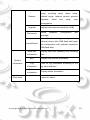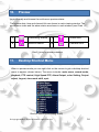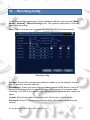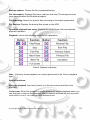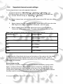
1
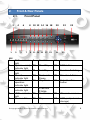
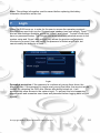
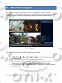
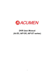
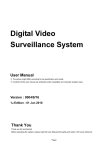
8 & 16 CHANNEL HDA DVR Q-HAD-IO8 Q-HAD-IO16 User’s Manual V1.0 11 / 2014 Contents 1 Important Safeguards & Warnings 2 Front & Rear Panels 3 Basic Information 4 Alarm Input & Output Information 5 Startup 6 Turn Off 7 Login 8 Logout 9 Main Menu 10 Preview 11 Desktop Shortcut menu 12 Recording Config 13 Backup 14 Snapshot Storage 15 Playback 16 Network Setup 17 Alarm 18 PTZ Control 19 System Setup 20 Web Monitoring 21 Special Function 22 Multi-Channel Playback 23 File Storage 24 FAQ: Troubleshooting Appendix 1: Remote controller operation Appendix 2: Mouse operation Appendix 3: Detailed Specification © Copyright OYN-X® All documentation rights reserved. 5 6 8 8 9 9 10 11 12 16 16 17 19 21 22 24 25 37 39 76 78 80 81 82 90 91 92 1 WELCOME Thank you for purchasing the 8 & 16 Channel High Definition Analogue Nitro DVR. This user’s manual is designed to be a reference tool for your CCTV system. The product series has an array of integrated features, which gives great practical advantages to the user. As well as being able to record in full D1 @ 25fps (real-time), it can also provide high definition 720p quality recorded footage @ 12fps (HDA). The system incorporates intelligent analysis of incoming video footage to ensure only relevant information is recorded. For added ease of use the DVR is designed so that it offers a streamlined setup process. The user can achieve great ease of use, applicability, expansibility and detailed video surveillance through this advanced design. Main Features: Real-time surveillance - Spot interface. - Analog interface. - VGA and HDMI video display ports. Storage - Redundant hard disk dormancy management to relieve system from high levels of heat. - Reduces power consumption and extends device life-span. - Special storage format which ensures data safety. Compression - H.264 Real-time compression by each individual hard disk, which ensures that the audio and video signals have stable synchronisation. © Copyright OYN-X® All documentation rights reserved. 2 Backup - Inbuilt SATA and USB interface for an external storage device through net download the files in the hard disk Playback - Individual real-time video recording as well as searching, playback, network surveillance, recording checking, downloading and more. - Multi-tile playback mode. - Zoom into arbitrary regions. Remote Network Operation - Ethernet connection for real-time surveillance across a structured network. - Remote PTZ control. - Monitor recorded footage and real-time playback. Alarm linkage - Alarm activated video recording, tour, message, buzzer, email, and FTP. Communication interface - RS485 interface provides a connection for the alarm input and PTZ control. © Copyright OYN-X® All documentation rights reserved. 3 - RS232 interface provides an extended keyboard connection to work in conjunction with the master keyboard. Also allows as interfacing with another computer with a serial port connection, to perform system maintenance & upgrades, matrix control, etc. - Standard Ethernet network interface fulfills the telecommuting function © Copyright OYN-X® All documentation rights reserved. 4 1. Important Safeguards and Warnings 1.Electrical safety All installation and operation here should conform to your local electrical safety codes. We assume no liability or responsibility for all the fires or electrical shock caused by improper handling or installation. 2.Transportation security Heavy stress, violent vibration or water splash are not allowed during transportation, storage and installation. 3.Installation Keep upwards. Handle with care. Do not apply power to the DVR before completing installation. Do not place objects on the DVR 4.Qualified engineers needed All the examination and repair work should be done by the qualified service engineers. We are not liable for any problems caused by unauthorized modifications or attempted repair. 5.Environment The DVR should be installed in a cool, dry place away from direct sunlight, inflammable, explosive substances and etc. This series product shall be transported, storage and used in the environment ranging from 0℃ to 55 ℃ 6. Accessories Be sure to use all the accessories recommended by manufacturer. Before installation, please open the package and check all the components are included. Contact your local retailer ASAP if something is broken in your package. © Copyright OYN-X® All documentation rights reserved. 5 2. Front & Rear Panels Front Panel 2.1. 2 1 4 3 6 5 7 8 10 12 14 16 18 20 9 11 13 15 17 19 21 KEY: 1 Shift indicator light 2 System ready indicator light 3 Alarm indicator light 4 Record indicator light 5 Outside operation indicator light 6 Network indicator light 7 8 HDD indicator light Previous File 22 24 23 9 Next File 17 Record 10 Slow Play 18 ESC button 11 Fast Play 19 Function Switching 12 Backwards Pause Play Pause 20 Direction & Enter 21 Select/confirm button 14 Previous Frame 22 Power switch 15 Next Frame 23 IR remote receiver 16 Play 24 USB port (external storage) 13 © Copyright OYN-X® All documentation rights reserved. 6 Rear Panel (16 Channel device shown below) 2.2 2 1 1 5 9 RS485 Alarm input/out puts HDMI port RS485 Port (PTZ) 3 4 5 6 10 7 8 9 11 2 Audio inputs RCA 3 BNC Video inputs 4 BNC Audio output 6 Ethernet Internet port VGA video output 7 USB ports 8 RCA Stereo inputs 10 11 © Copyright OYN-X® All documentation rights reserved. DC12V Input 7 3. Basic installation 3.1 HDD installation Please install the Hard disk before using this product for the first time. Please connect the HDD power and data cable correctly (our product can support 1 or 2 or 4 or 8 HDDs). How many HDDs it can support depends on which kind of product the buyer purchases. Note: the device can run normally without HDD, but cannot do record and playback. 3.2 Mouse connection To connect the mouse you have the option of using either of the two USB ports attached to the rear panel. Both can be used for a mouse, flash disk, WIFI or 3G module/dongle, etc. 3.3 Monitor connection To view DVR menu and interface system, you will need to connect a computer monitor to the device. The rear panel has VGA and HDMI video output ports to connect the monitor to. 4. Alarm Input and Output Connections 4.1. Alarm input Alarm input is grounding alarm input. Alarm input demand is the grounding voltage signal. When the alarm is connected with two DVRs or connected with DVR and other equipment, it should be isolated by relay. 4.2 Alarm output Alarm output cannot be connected to a high-power load (no more than 1Amp). When forming the output loop you must prevent high current levels from damaging the relay. Please use the contact isolator when there is a highpower load. © Copyright OYN-X® All documentation rights reserved. 8 4.3 PTZ decoder connections Make sure the grounding of the PTZ decoder and DVR are shared otherwise the common-mode voltage will lead to the PTZ control failing. It is recommended to use shielded twisted pair. Try to incorporate precautions to prevent electrical damage from an unstable mains power source. Please use surge protection devices or uninterruptible power supplies. In the outlying end connect 120Ω resistance paralleled to reduce inflections and insure the signal quality. The 485 AB lines of DVR cannot be connected with other 485 output equipment in parallel. The voltage between the AB lines of the decoder must be less than 5V. 4.4 Front equipment grounding note Bad grounding can lead to the burnout of the internal chipset. 4.5 Alarm input type unlimited The DVR alarm output port is set to a constant opening type. 5. Startup Once you have setup the peripheral device connections, HDD installation and turned on the power to the DVR, turn on the power switch located on the back panel. The indicator on the front panel will illuminate, which will signify the device has turned on successfully. After starting up, you will hear a beep; the default output to the monitor is the multi-window mode. Note: If the circumstance occurs when the power is abnormal or has been cut, please switch off the device. When you switch the power back on the DVR will automatically recover its previous state before it had been shut down. 6. Turn off There are two methods to turn off the DVR, either the soft switch or the hard switch. - Soft switch: Entering [Main menu] and choosing [Logout] in the [turn off the system] option. - Hard switch: Pressing the power supply switch. © Copyright OYN-X® All documentation rights reserved. 9 Note: The settings information must be saved before replacing the battery otherwise information will be lost. 7. Login When the DVR boots up, in order for the user to access the operating system’s functions they must login via the ‘System Login’ window (see next image). There are two user settings available, which are ‘admin’, and ‘guest’. To start off with they have no passwords setup. The ‘Admin’ user account allows unlimited access to the system setup and ‘Guest’ user account only allows the preview and playback functions to be used. User can modify the password of Admin and Guest, but cannot modify the authority of them. Login Password protection: If the password is continuously wrong three times, the alarm will start. If the password is continuously wrong five times, the account will be locked. (By rebooting the DVR after 30mins after being locked out, it will automatically allow access to the system login). To prevent this from happening, please revise and remember user name and password before logging back into the system. © Copyright OYN-X® All documentation rights reserved. 10 When you login, the system main menu is shown as below. Main Menu Window 8. Logout You have two options: Logout, or Reboot. You can use the desktop shortcut menu or enter the [main menu] to access the Logout Menu. Logout window 【Logout】Quits the menu. Offer password next time you want to log back in. 【Reboot】Quits the system. Reboot up the system. © Copyright OYN-X® All documentation rights reserved. 11 9. Main Menu Main menu navigation: Main menu Sub menu Config Record Function Set the recording configuration, recording type and recording time section Playback Set recording search, recording play and Storage video file storage. Backup Detect backup device, format device and backup the selected files. Set the motion detect alarm channel, Motion detection sensitivity, area, linkage parameters: defending time section, alarm output, screen hint, recording, screen shot, PTZ, patrol, buzz, email and FTP upload. Set Alarm Video blind camera mask alarm channel, sensitivity, linkage parameters: defending time section, alarm output, screen hint, recording, screen shot , PTZ, patrol, buzz, email and FTP upload. Set video loss alarm channel, linkage Video parameters: defending time section, alarm loss output, screen hint, recording, screen shot , PTZ, patrol, buzz, email and FTP upload © Copyright OYN-X® All documentation rights reserved. 12 Set alarm input channel, equipment type, linkage parameters: defending Alarm section, alarm input recording, screen shot , PTZ, patrol, buzz, output, time screen hint, email and FTP upload Set alarm mode: configuration, manual, Alarm output Exception handling shut down. No HDD, HDD error, HDD capacity is not enough, network cut, IP Conflict, linkage parameters, screen hint or buzz alarm. Set Intelligent analysis algorithm rule: trajectory display, sensitivity, minimum pixel, alert mode,and setting linkage parameters: period, alarm output, screen prompt, record, PTZ, tour, buzzer, EMAIL, FTP upload. Set system time, data format, language, General configuration hard disk full time operation, machine number, video format, output mode, summertime, stay time Set main (extra) coding parameter: code System configuration Encode configuration mode, resolving ability, frame rate, code stream control, image quality type, code stream value, frame between value, video/audio enable. Network configuration Set basic network parameters, DHCP and DNS parameters, network high speed download © Copyright OYN-X® All documentation rights reserved. 13 NetService PPPOE, NTP, Email, IP preview, DDNS parameter Set channel title, preview hint icon state, GUI display transparency, cover area, time title, channel title fold. PTZ configuration RS485 Device Set channel, PTZ protocol, address, baud rate, date bit, stop bit, check Set serial port function, baud rate, date bit, stop bit. Tour Set patrol mode and interval time Spot Set Spot tour mode and time interval Digital Hard disk management User management Set channel mode, check channel status and configure the digital channel, etc. Set appointed hard disk as read-write disc, read-only disc or redundant disc, clear data, resume date, etc. Modify user, team or password. Add user or team. Delete user or team. Break the connection with the already Management tools Online user logged in user. Lock the account after an attempted unauthorised access until next DVR reboot. Adjust Output adjust upside, downside, nearside, starboard distance, black margin vertical & horizontal. Automatic maintenance Set automatic reboot system and automatic deleting files. © Copyright OYN-X® All documentation rights reserved. 14 Resume setup state: common setup, code setup, Restore recording setup, alarm setup, network setup, network service, preview playback, serial port setup, user management Upgrade Device Info upgrade with external device(like USB) device hardware configuration and message Export the device's log or configuration to Import/Export external device (like USB flash disk);Input the configuration with external device(like USB flash disk). Hard disk information System information time BPS Display code stream information Log Clear all log information according to the information Edition information Shut down Display hard disk capability and recording log video and time Display edition information Logout or reboot. © Copyright OYN-X® All documentation rights reserved. 15 10. Preview Login normally and choose the multi-menu preview status. The system date, time and channel title are shown in each viewing window. The surveillance video and the alarm status are shown in each window (see Chart 1). 1 Recording status 3 Video loss 2 Motion detect 4 Camera lock Chart : icons on preview window 11. Desktop Shortcut Menu When in preview mode you can right click on the mouse to get a desktop shortcut menu to appear (shown below). The menu includes: main menu, record mode, playback, PTZ control, High Speed PTZ, Alarm Output, color Setting, Output adjust, Logout, view mode shift, spot. Shortcut menu in full analog (DVR) © Copyright OYN-X® All documentation rights reserved. 16 12. Recording Config To set the recording parameters in the surveillance channel, you can enter [Main Menu] > [Record] > [Record Config] to set. The system’s default set to 24 hours continuous recording. Note: There is at least one read-write hard disk if the DVR records normally. Recording Config Channel: Choose the corresponding channel number to set the channel. Choose the ‘All’ option to set every channel. Redundancy: Check this option when you have a second HDD drive to use as a backup redundancy option in case the primary HDD runs out of free space whilst recording. First HDD is a read-write disk; the second is a redundant disc ready as a spare. Length: Set the time length of each video file. 60 minutes is default length. Prerecord: Record 1-30 seconds before the action (file length is decided by the stream). © Copyright OYN-X® All documentation rights reserved. 17 Record Mode: Set video state: Schedule, manual and stop. Schedule: Record according to the set video type (regular, detect and alarm) and time section. Manual: Selecting this option will allow you to manually control recording operations on each channel. Stop: Selecting this option will make the according channel stop recording when it is in any set state. Period: Set the times during the week when you want the DVR to start and stop recording. The recording will start and stop only in the set range. Recording Type: - Regular:Selecting this option will initiate regular recording in the set time section. The video file type is ‘R’. - Detect:Selecting this option will set the motion detect trigger function when there is video blindness (blocked camera view) or video signal loss. When the alarm is set as open recording, the ‘Detection recording’ state is set to ‘on’. The video file type is ‘M’. - Alarm:Selecting this option will set the external alarm trigger signal in the set time section. When the alarm is set as ‘Open recording’, the ‘Detection recording’ state is on. The video file type is ‘A’. © Copyright OYN-X® All documentation rights reserved. 18 13. Backup You can back up the video files to external storage device through these setup menus. Note:The storage must be installed before the file backup. If the backup is terminated, the already backup can playback individually. Backup option screen 【Detect】Detect the storage connected with the DVR such as hard disk or universal disk. 【Backup】Click backup button and the dialog box is popped up. You can choose the backup file according to the type, channel and time. © Copyright OYN-X® All documentation rights reserved. 19 Backup option screen 2 Remove: Clear the file information. Add: Show the file information satisfying the set file attributes. Backup format: configure the backup file format, according to what you require. You can choose between two different formats, which are H.264 or AVI. Start/pause: Click the play button to start the backup and click the pause button to stop the backup. Note:During backup you can exit the page layout to carry out other functions. 【Burning】the file will be burned synchronously after you have clicked this. 【Erase】Choose the file you wish to delete and click this button to delete the file. 【Stop】Stop the backup. © Copyright OYN-X® All documentation rights reserved. 20 14. Snapshot Storage This option allows you setup the system to take still snap shots from monitor image and save on the allocated HDD. Parameter setting:【Main menu】>【Record】>【Snapshot】to select related setting, see pic 3, the function is closed in default. Note: To instruct system to save snapshots on the primary HDD, set Snap at 【Main Menu】->【Advanced】->【HDD Manage】->【Snapshot】 Pic 3 Snapshot PreSnap: Set how many seconds of pre-recorded footage (stored in the memory) is added on to the beginning of the snapshot. You can refer to ‘6. Record Config’ section for a very similar description on how to setup the ‘Snapshot’ options. © Copyright OYN-X® All documentation rights reserved. 21 15. Playback There are two methods for you to play the video files stored on the hard disk: In the desktop shortcut menu. Main Menu > Record > Playback. 1. 2. When you enter the playback interface you can playback video from a multiple of channels at the same time. Note: The hard disk that saves the video files must be set as read-write. Pic 4: Playback Key: Back up options File information File searching File backup Operation playback time code Playback control panel © Copyright OYN-X® All documentation rights reserved. 22 Backup options: Choose the file to playback/backup. File information: Displays Start time, end time and size (The storage must be large enough before the file backup begins). File searching: Search for specific files according to the search parameters. File Backup: Displays the backup files stored on the HDD. Operation playback time code: Displays the current time code and selected playback operation. Playback: refer to the following sheet for full explanation: Chart 2: Playback controls key Note:Frame by frame playback can only be performed in the ‘Pause’ playback state. Special functions: Accurate playback: Input time (h/m/s) in to the time column and then click playback. Local zoom: When the system is in single-window full-screen playback mode, you can drag your curser on the screen to select a section and then left click mouse to local zoom in or out. You can right click mouse to exit. © Copyright OYN-X® All documentation rights reserved. 23 16. Network Setup To configure network settings: 【Main Menu】> 【System】> 【Network】 - IP address: Set the IP address. Default: 192.168.1.10. - Subnet Mask: Set the subnet mask code. Default: 255.255.255.0. - Gateway: Set the default gateway. Default: 192.168.1.1. Pic 5: Network setting You can manually configure the options above to correctly setup your local network by replacing the default IP addresses with the ones allocated to the current router. According to the default setup, the default gateway is generally the router IP address, so enter IP address (e.g.192.168.1.10) in the web browser to be able to operate the security surveillance system from different PC terminals within the local network. © Copyright OYN-X® All documentation rights reserved. 24 17. Alarm Alarm functions include: motion detect, video blind, video loss, alarm input and alarm output, Abnormality, intelligent analysis. 17.1. Alarm output Please check current channel status: “○” means it is not in alarming status, “●” means it is in alarming status. You can use desktop shortcut menu or click [main menu]> [alarm function]> [alarm output] to enter the alarm output interface. Alarm output 【Configuration】: Alarm is on according to the configuration. 【Manual】: Click the all button and the according channel is alarming no matter the channel in any state. 【Stop】: Click the stop button and the according channel stops alarming no matter the channel in any state. © Copyright OYN-X® All documentation rights reserved. 25 17.2. Motion Detect Motion Detect Motion detection setup: Within this configuration menu you are given setup options to activate a number of elements of the motion detection feature. This includes setting up the alarm trigger, linkage record and also to instruct a PTZ camera to move to a preset position for when the motion sensor has detected movement (between certain periods of time). To set these options: Choose【Main Menu】>【Alarm】>【Motion Detect】, then enter the setup interface; Choose the camera channel you want to set and adjust the sensitivity level. You will also be able to adjust the time period of alarm surveillance. Set the monitor area (click the ‘Set’ button next to ‘Region’), select the areas you want, the ‘Default’ setting will make all areas motion sensitive, then right click to choose ‘Up window’. In the second section of the motion detect options, you can customise: © Copyright OYN-X® All documentation rights reserved. 26 What period you would like the motion detect to be active Specify the length of the alarm trigger delay Set an interval period length between alarm activations Which channels to set motion detection upon Tour channel setup PTZ activation time period setup (with activation delay option) Which channels to allow snapshots from the footage Whether you want an alert message to be displayed, Sending an email notification to alert you of the triggered motion sensor alarm (need to set email parameters at net service) Activating the buzzer (local buzzer). To upload trigger data through the FTP Set other channels alarm parameter following step 2 and step 3. Note: Video blind, video loss and alarm input’s setup method are similar with motion detection. Motion detection menu options: 【Channel】Choose the set motion detect channel. 【Enable】■ means that the motion detect function is on. 【Sensitivity】 You have six sensitivity levels to choose from: Lowest, Lower, Middle, High, Higher, and Highest.. 【Region】Click [set] to enter the set area. The area is divided into PAL22X18. Red blocks represent the motion detect defensive area. White block means the unfenced area. You can set the area as followed, Drag the mouse and draw the area. Default: all selected blocks are the detection area. Select Region © Copyright OYN-X® All documentation rights reserved. 27 【Period】Trigger the motion detect signal in the set time section. You can set according to week or you can set uniformly. Each day is divided into four time sections. Set the time section 【Interval】Only one alarm signal is turned on even there are several motion detect signals in the set interval. 【Alarm output】Start the external equipment of corresponding linkage alarm when the motion detect alarm is turned on. 【Delay】Delay a few moments and stop when the alarm state is turned off. The range is 10~300 seconds. 【Record channel】Choose the recording channel (multiple option supportive). Trigger the video signal when the alarm is turned on. Note: Set in the [recording setup] and perform the linkage recording. Start detecting video files in the corresponding time section. 【Tour】■ means that the selective channel is single window alternate patrol preview. The interval is set in the [Main Menu]>[System] > [Tour]. 【PTZ Activation】Set the PTZ activation when the alarm is turned on. Note:to link PTZ, you need to go [Shortcut menu]->[PTZ control] to set preset point, cruise between points & interval time, etc. © Copyright OYN-X® All documentation rights reserved. 28 PTZ Activation under hybrid mode 【Delay】When alarm is over, recording will last some seconds(10~300sec),then stop. 【Show message】Pop the alarm information dialog box in the local host computer screen. 【Send EMAIL】■ means sending an email to user when the alarm is turned on. Note: Set in the [NetService] and send email. 【FTP upload】to tick it, the video & picture of related record channel & snapshot channel will be uploaded to assigned position. Note:FTP upload need be set at [Netservice] 【Buzz】When alarm is triggered, the device will emit a buzzing sound. 17.3. Abnormality The DVR’s operating system will constantly scan the current software and hardware of the device for any abnormal events such as: No Disk (No hard disc drive available) Disk Error No Disk Space Network Disconnection IP Conflict (IP address is incorrect for remote connection) If one of these system errors occurs the device will alert you with such as show message and buzzer. © Copyright OYN-X® All documentation rights reserved. 29 Abnormal menu screen 【Event Type】Selecting abnormity you want to inspect 【Enable】 Select it to make sure abnormal function workable 【Show message】 Automatically alarm cue dialog box come out of the main screen 【Buzzer】 Device will have one long nosie “di” while alarm is happening © Copyright OYN-X® All documentation rights reserved. 30 17.4. Intelligent Analysis This options menu will allow you to setup specified picketed areas within the footage frame, so that when an object has been analysed entering the picketed area the alarms will be triggered. Intelligent Video Analysis Intelligent analysis function: you can set in two rules: picket line and picket area. You can only use the Video Analysis function on Record Channel 1; no other channels can be used. © Copyright OYN-X® All documentation rights reserved. 31 st 【Channel No.】Only shows “1” at present, only the 1 channel with maximum resolution of 1080P. 【Enable】tick this to enable the video analysis function, then can go for further setting, 【Algorithm rule】at drop-down box to choose the algorithm rule of detection, 【Rule】choose different algorithm rules, the related setting page is different. Cordon: Show traces: tick it to enable, when alarm triggers, there will be red box around moving objects. Sensitivity: based on different requirements, there are 3 options in the drop-down box Minimum image distance: the range is between 0~30 %, the more flexible the less image distance. Alert way there are 2 kinds:cordon and warning area. Cordon:Can set 3 prohibited directions: bidirectional prohibited, from top to bottom (from left to right), from bottom to top (from right to left), when the setting cordon is too slope, show with from left to right / from right to left, otherwise will be from top to bottom / from bottom to top, when the moving object meet preset cordon rules, the alarm will be triggered; Warning area: can set 3 kinds of prohibited directions: bidirectional prohibited, enter and leave, when the moving object meet preset warning area rules, alarm will be triggered. Rules: click setting > enter the rule setting page > right click mouse > choose add >use mouse to fix two or more point > and then connect them to form a line or an irregular region. Once you have done those steps, a box of prohibited direction options will appear. Choose one of them > right click mouse > click ‘Yes’ > return to previous page > click ‘Yes’, setup is now complete. Picket line rules: you can forbid bidirectional motion, which includes; from up to down (from left to right), from down to up (from right to left), 2 forbidden directions, when the moving objects meet the picket line rules, alarm will be triggered. Note: when it is overpitched, it will show the direction from left to right / right to left, otherwise it will show the direction from up to down / down to up. Rules: you can choose to forbid bidirectional movement, entering or leaving footage frame, or movement in 3 different directions, so that when the moving objects meet these picket area rules the alarm will be activated. © Copyright OYN-X® All documentation rights reserved. 32 I. [Main Menu] > [Alarm] > [Intelligent Analysis], enter video analysis setting interface, enable this function. Rule setting 1. Click ‘Rule’ to enter the rule setting interface, see pic 8: 2. Enable ‘Show traces’ function, adjust the level of sensitivity and minimum image distance. The ‘Alert way’ section will allow you define what type of alarm triggers the system analyses. 3. Once you have set your rules, you need to set the picket mode, choose picket line or picket area. Click setting to enter the config interface, then right click the mouse and choose ‘Add’. Use the mouse to set two or more points and connect them to form a line or an irregular area. After that has been set an option box of forbidden direction will appear, choose one option and right click mouse, then click yes return to pre-interface, click yes to finally finish alarm rules setting. 4. Next you need to set the alarm control period steps. The taken linkage measures are the same as step 2 and step 3 in ‘Alarm setting’ 10.1. © Copyright OYN-X® All documentation rights reserved. 33 5. When video analysis alarm is triggered, there will be red box line in the preview image. The intelligent analysis function mainly includes the 2 facets detailed below Touch line detection: bidirectional touch line, single-direction touch line. 6. Area detection: enter alarm, leave alarm. © Copyright OYN-X® All documentation rights reserved. 34 Items care 17.5. Show traces: tick this to enable, when this function is triggered, there will be a red box shown around the moving object. Sensitivity: based on different requirement, there are 3 options in the dropdown box. Minimum image distance: range between 0~30 %,the more flexible the less image distance. Alert way: three modes available: Items stranded: object appears within warning area, and the size of object meets the rules of minimum image distance, alarm will be triggered (see image below). Items stolen: object disappears within warning area, and the size of object meet the rules of minimum image distance, alarm will be triggered © Copyright OYN-X® All documentation rights reserved. 35 Illegal parking: this way is similar to ‘Items stranded’ (see image below). Rule: click Set, enter the setting page of rule, right click mouse, choose add, use mouse to fix several points and then connect them to form an irregular region, right click mouse, click Yes, return to previous page, click Yes, alarm rule setting if finished. Rule setting - items care © Copyright OYN-X® All documentation rights reserved. 36 18 PTZ Control The steps below will explain how simple it is to control a PTZ camera: 【Main Menu】>【System】>【PTZ】, to set channel parameter, protocols, etc. 1. In order to view the PTZ camera video feed, select ‘Preview status’ to enter single window camera view. 2. Right click the mouse button, choose PTZ control to control the normal function, or choose high-speed. Click left mouse button to operate the PTZ directly, moving the mouse controls the direction of PTZ, use the scroll wheel in the middle of the mouse to zoom in or zoom out. 3. Operation interface is as followed. The functions include: PTZ direction control, step, zoom, focus, iris, setup operation, patrol between spots, trail patrol, boundary scan, assistant switch, light switch, level rotation and so on. Note: Decoder A(B) line connects with DVR A(B) line. 4. 5. Click [main menu] > [system configuration] > [PTZ setup] to set the PTZ parameters. The PTZ functions are decided by the PTZ protocols. PTZ setup 【Speed】: Set the PTZ rotation range. Default range: 1 ~ 8. © Copyright OYN-X® All documentation rights reserved. 37 【Zoom】: Click the camera. 【Focus】: Click camera . 【Iris】: Click / button to adjust the iris of the camera. 【Hide】: Current interface will be temporarily hidden after click it. 【Direction control】: Control the PTZ rotation. 8 directions control is supportive.(4 directions in Front panel is supportive ) 【High speed PTZ】: Full-screen shows channel image. Left press mouse and control PTZ to rotate orientation. Left press mouse and then rotate the mouse to adjust the zoom multiple of the camera. 【Set】: Enter the function operation menu. 【Page switch】: Switch between different pages. / button to adjust the zoom multiple of / © Copyright OYN-X® All documentation rights reserved. button to adjust the focus of the 38 19 System Setup Set the system parameters such as: General, Encode Network Net service GUI display PTZ configure/RS485 device RS232 Tour setup Spot and digital 19.1 General General setup 【System time】Set the system data and time. 【Date format】Choose the data format: YMD, MDY, DMY. © Copyright OYN-X® All documentation rights reserved. 39 【Date Separator】Choose list separator of the data format. 【Time Format】Choose time format: 24-hour or 12-hour. 【Language】supports 29 languages : Arabic, Czech, English, Finnish, Greek, Indonesian, Italian, Japanese, Portuguese, Russian, Thai, T-Chinese, S-Chinese, Turkish, Brazilian, Bulgarian, Farsi, French, German, Hebrew, Hungarian, Polish, Romanian, Spanish, Swedish, Vietnamese, etc. 【HDD full】Choose stop record: Stop recording when the hard disk is full. Choose overwrite: Cover the earliest recording files and continue recording when the hard disk is full. 【DVR No.】Only when the address button on the remote control and the corresponding DVR number is matched, then the remote operation is valid. 【Video Standard】PAL or NTSC. 【Auto Logout】Set the latency time in the range of 0-60. 0 means no latency time. 【Machine Name】Set the device's name. 【DST】Choose the summer time option and the pop up dialog box appears: DST (week) © Copyright OYN-X® All documentation rights reserved. 40 DST (date) 19.2 Encode This menu will allow you to set the video/audio code parameter: video file, remote monitoring and so on. Set every main stream parameter in the left part, and then set the extra stream parameter in the right part. Note: extra stream introduces a video compression technique that was applies to multi-channel simultaneous playback , Dial-up multi-channel real-time monitor working under poor bandwidth strength, or for mobile monitor, etc. Picture 4.20 Encode setup © Copyright OYN-X® All documentation rights reserved. 41 Independent channel code setting: 【Channel】Choose the channel number. 【Compression】Standard H.264 main profile. 【Resolution】Resolution type:1080P/720P/960H/D1/ HD1/CIF / QCIF. 【Frame Rate】P:1 frame/s~25 frame/s; N: 1 frame/s~30 frame/s 【Bit Rate Type】You can choose limited code stream or variable code stream. When you choose the variable code stream there are six image quality options. Under the limited code stream,you can choose the code stream manually. 【Bit Rate】Set the code stream value to modify the image quality. The larger code stream value the better image quality: - 1080P(1024~8192kbsp) 720P(1024~4096kbps) 960H(869~4096kbps) D1(512~2560kbps) HD1 (384~2048kbps) CIF (64~1024kbps) QCIF (64~512kbps) 【Frame Interval】can choose the range 2~12s 【Video/Audio】When the icons are all displayed in reverse, the video file is the video and audio multiplex stream. Extra stream Settings: 【Extra stream】is used for client side monitoring & mobile monitoring. 【Channel title】select channel title and then to choose whether need enable video & audio. The resolution, frame rate, bit rate type settings is the same as main stream. © Copyright OYN-X® All documentation rights reserved. 42 19.3 Network Setup Network Menu 【Net Card】You can choose cable network card or wireless network card. 【DHCP Enable】Obtain IP address automatically(not suggested) Note:DHCP server is preinstalled. 【IP address】Set the IP address. Default: 192.168.1.10. 【Subnet mask】Set the subnet mask code. Default: 255.255.255.0. 【Gateway】Set the default gateway. Default: 192.168.1.1. 【DNS setup】Domain Name Server. This translates the domain name into an IP address. The IP address is offered by network provider. The address must be set and reboot then it works. 【Media port】Default: 34567. 【HTTP port】Default: 80. © Copyright OYN-X® All documentation rights reserved. 43 【HS Download】 【Transfer Policy】There are three strategies: self-adaption, image quality precedence and fluency precedence. The code stream will adjust according to the setup. Self-adaption is the tradeoff between the image quality precedence and fluency precedence. Fluency precedence and selfadaption are valid only when the assistant code stream is turned on. Otherwise image quality precedence is valid. 19.4 Net Service Choose the network service option and click the set button to configure the advanced network functions or double click the service button to configure the parameters. NetService Menu © Copyright OYN-X® All documentation rights reserved. 44 【PPPoE setup】 PPPOE Enable:Reverse ■ means choose, setting can become effective. Input the user name and password that ISP(Internet service provider)provides. After saving it, reboot up your system. Then the DVR will build a network connection based on the PPPoE. The IP address will change into dynamic IP address after above operation is well done. Operation:After PPPoE dialing has successfully looked up the IP address in the [IP address] and obtain the current IP address. Then use this IP address to visit the DVR through user port. 【NTP setup】 NTP © Copyright OYN-X® All documentation rights reserved. 45 The NTP server must be installed in the PC. Enable:Reverse ■ mean choose,setting can become effective. Host computer IP: Input the IP address installed NTP server. Port: Default: 123. You can set the port according to NTP server. Time zone: Update Period: The same with the NTP server check interval. Default: 10minutes. 【EMAIL setup】 If the alarm is triggered or the alarm snapshots are taken, you can setup the DVR to send an email containing alarm information and the photos to an appointed email address. EMAIL SMTP server: Email server address. It could be an IP address or domain name. Domain name can be translated only it is the correct DNS configuration. Port: Email server port number. SSL: Decide whether using Secure Socket Layer protocol to login. User Name: Apply the email server user name. Password: Input the password corresponding to the user. Sender: Set the email sender address. © Copyright OYN-X® All documentation rights reserved. 46 Receiver: Send the email to appointed receivers when the alarm is turned on. You can set three receivers at most. Title: You can set as you wish. 【IP Filter setup】 When choosing the white list, only the listed IP address can connect to the DVR. The 64 IP addressed are supportive in the list. When choosing the black list, the listed IP address cannot connect to the DVR. The 64 IP addressed are supportive in the list. You can delete the set IP address by √ in the options. Note:When the same IP address is in the white and black list at the same time, the black list precedence is higher. IP Filter © Copyright OYN-X® All documentation rights reserved. 47 【DDNS】 DDNS setup DDNS: Dynamic Domain Name Server. Local domain name: Provide the domain name registered by DDNS. User name:Provide the account registered by DDNS. Password:Provide the password registered by DDNS. When the DDNS is successfully configured and start, you can connect the domain name in the IE address column to visit. Note:The DNS setup must be configured correctly in the network setup. 【FTP setup】 FTP is available only when alarm is triggered, or alarm activates record and snapshot functions, it will upload the related record and snapshot pictures to FTP server. © Copyright OYN-X® All documentation rights reserved. 48 FTP setup 【Enable】Click Enable, then all settings will become available 【Server IP】IP address for FTP server 【Port】Domain Port of FTP, default 21 【User Name】User name of FTP 【Password】Password of user 【Anonymous】:enable anonymous, no need to set user name and password 【Max File Length】Max length for upload files for every data packet, default is 128MB 【Dir Name】:The directory of the upload file. Note: Only Users are to upload files only have permission/clearance to do so. 【ARSP】 Startup DDNS server to add devices and manage it in the DDNS server © Copyright OYN-X® All documentation rights reserved. 49 ARSP [Type]: choose "DNS" [Enable]: ■ means it is chosen [Sever IP]: IP address of DDNS server [Port]: Port No. of device, related DDNS server listen port [User name] the user name that device can log in DDNS server [Password] the password related to the user name. [Refresh cycle]:Time interval between device and DDNS when synchronised. Note: Please set up server before using DDNS. © Copyright OYN-X® All documentation rights reserved. 50 【Alarm center】 When the alarm has been triggered, you can send report alarm information to the alarm server. Alarm server setting 【Protocol type】GENERAL 【Enable】To tick it means enable. 【Server IP】IP address of Alarm Server 【Port】Device Port No. 【Alarm Report】Tick it means to report alarm information to server. 【Log Report】Tick it, means to report log to server. 【Wireless Config】 ADSL through 3G net card, use CMS to visit and config the device © Copyright OYN-X® All documentation rights reserved. 51 Wireless Config 【Enable】Choose Enable to make all settings available 【Type】Dial type, default AUTO 【Wireless AP】3G access point 【Dial Number】3G Dial Number 【User Name】User name of 3G 【Password】Password of dial user 【IP Address】IP address, obtained from dial. © Copyright OYN-X® All documentation rights reserved. 52 【Mobile Monitor Setup】 To visit the device via your smart mobile phone you need to port forward your router. Please setup your router so that it maps out the allocated port number and use CMS to monitor and operate it using protocols. Mobile Monitor Setup 【Enable】: Select it to make sure abnormal function workable 【Port】: The mobile monitoring port, this is the port number you need to use when mapping your router. © Copyright OYN-X® All documentation rights reserved. 53 【UPNP】: UPNP protocol allows you to auto port forwarding on router The precondition of using this function is to make sure the UPNP function of router is enabled. UPNP 【Enable】: Choose Enable to make sure all UPNP settings are available 【HTTP】: Router will automatically distribute HTTP port for the device, during web browser viewing. 【TCP】: Router will automatically distribute TCP port for the device, when monitoring via CMS. 【Mobile Port】: Router will automatically distribute Mobile Port for the device when using your smart phone to monitor the DVR. © Copyright OYN-X® All documentation rights reserved. 54 【WIFI】 The DVR connects to wireless router via WIFI module then it visits it through the IP address, the precondition of using this function is to make sure the DVR have connected with WIFI modern. WIFI configure 【Search】:click【search】to search all the available wireless device in current range. 【enable】:tick it to enable firstly, then go for further setting. 【auto obtain IP address】:tick it to enable, device will auto obtain a WIFI IP. 【SSID】:wireless LAN name, auto match to the wireless device u connected. 【Password】:wireless network password of router; 【IP address】: to set the IP address of device, default is 192.168.1.12 【subnet mask】:set subnet mask of device, default is 255.255.255.0 【gateway】:set gateway of device, default is 192.168.1.1 © Copyright OYN-X® All documentation rights reserved. 55 【RTSP】 Surveillance via cross-browser (Safari, Firefox, Google chrome ) and also using VLC software. This function only for monitor but cannot control the device. RTSP setting 【Enable】:■ means enable, tick it firstly before setting. 【Port】:the default port is 554 19.5 GUI Display Configure the video output parameters including the front output mode and encode output mode. Front output:The local preview mode includes: channel title, time display, channel display, record status, alarm status, transparency and region cover. Encode output:In the network surveillance and video file mode include: channel title, time display, channel display, record status, alarm status, transparency and region cover. © Copyright OYN-X® All documentation rights reserved. 56 The GUI display menu 【Channel Title】Click the channel name modify button and enter the channel name menu. Modify the channel name. 【Time Display】 This means displaying the selective state. Display the system data and time in the surveillance window. 【Channel display】This means the selective state. Display the system channel number in the surveillance window. 【Record Status】This means the selective state. Display the system recording status in the surveillance window. 【Alarm Status】 This means the selective state. Display the system alarm status in the surveillance window. 【Transparency】Choose the background image transparency. The range is 128~255. 【Resolution】Set the display resolution. 【Channel】Choose the set code output channel number. 【Region Cover】This means the selective state. Click the cover area button and enter the corresponding channel window. You can cover the arbitrary using mouse. (Black region is for output) 【Time display】and 【Channel display】 set the display position of channel title and time title. © Copyright OYN-X® All documentation rights reserved. 57 19.6 PTZ / RS485 Device This menu will allow you to configure the attached PTZ or other device connected to the RS485 ports on the rear of the DVR. Pic 4.37 PTZ configure 【Channel】Choose the dome camera input channel. 【Protocol】Choose the corresponding dome protocol. (PELCOD as an example) 【Address】Set the corresponding dome address. Default: 1.(Note: The address must be consistent with the dome address.) 【Baudrate】Choose the corresponding dome baud rate length. You can control the PTZ and vidicon. Default: 115200. 【Data bits】Includes 5-8 options. Default: 8. 【Stop bits】Includes 2 options. Default: 1. 【Parity】Includes odd check, even check, sign check, blank check. Default: void. 【Protocol】choose related protocol of brand model 【Address】set with corresponding address, default is 1 【Baud rate】choose the baud rate that the related device uses, default is 115200 【Data bits】including 5-8 options,default is 8; © Copyright OYN-X® All documentation rights reserved. 58 【Stop bits】includes 2 options, default is 1 【Parity】Include odd check, even check, sign check, blank check. Default: void. 19.7 Tour Function This menu will allow you to set the patrol routine of the DVR. : This means that the tour mode has been enabled. You can choose the single-view, four-view, six-view of the single mode tour. Tour configuration menu 【interval】Set the patrol switch interval. The set range is 5-120 seconds. 【alarm tour】set the interval to shift alarm tour, range is 5-120 seconds, choose return when alarm ends, when alarm link to tour, system will auto shift to six-view after alarm finished. © Copyright OYN-X® All documentation rights reserved. 59 Remark:at preview mode, click upper right icon: / (Turn on / Turn off tour) 19.8 Channel Management Manage each camera’s channel status and mode. Initial channel manage screen Channel Status: This menu screen shows the status of the entire range of available channels (the information includes: Max Resolution, This Resolution, Connection Status). © Copyright OYN-X® All documentation rights reserved. 60 For example: When a channel is added to the device but it is not enabled ‘Not Configured’ will be displayed: © Copyright OYN-X® All documentation rights reserved. 61 Remark: when the current resolution is over the max resolution that the channel supported, then a red “X” will be shown on the preview image: 19.9 Advanced Manage tools menu including: HDD manage, account manage, online user, output adjust, auto maintain, upgrade. 19.9.1 HDD Manage Configure and manage the hard disk. The menu displays current hard disk information: hard disk number, input port, type, status and overall capability. The operation include: setup the write-read disk, read-only disk, redundant disk, hard disk format, resume default. Choose the hard disk and click the right function button to execute. Note:Read/Write Disk: The equipment can write or read data. Read-only Disk: The equipment can read data but can not write data. Redundant Disk: Double backup the video files in the write-read disk. © Copyright OYN-X® All documentation rights reserved. 62 HDD manage 19.9.2 Account Manage the user purview. Notes: 1. The character Max length is 8 bytes for the following user and user team name. 2. The blank space ahead or behind the character string is invalid. The middle blank in the character string is valid. Legal characters include: letter, number, underline, subtraction sign, and full stop. 3. There is no limit to the number of users and user groups you can have. You can add or delete the user group according to user definition. The factory setup includes: user\admin. You can set the team as you wish. The user can appoint the purview in the group. 4. The user management includes: group/ user. The group and user name cannot be the same. Each user only belongs to one group. © Copyright OYN-X® All documentation rights reserved. 63 Account management 【Modify User】Modify the existing user attribute. 【Modify Group】Modify the existing team attribute. 【Modify Password】Modify the user password. You can set 1-6 bit password. The blank ahead or behind the character string is invalid. The middle blank in the character string is valid. Note:The user who possesses the user control purview can modify his/her own or other users password. © Copyright OYN-X® All documentation rights reserved. 64 Modify password 【Add user】Add a user into the group and set the user purview. Enter the menu interface and input the user name and password. Choose the team and choose whether cover using the user. Cover using means that the account can be used by multiple users at the same time. Once you have chosen the team, the user purview is the subclass of the team. We recommend that the common user’s purview is lower than the advanced user. © Copyright OYN-X® All documentation rights reserved. 65 Add User 【Add Group】Add a user group and set the purview. There are 33 different purviews: Which allows you to either shut down the equipment, real time surveillance, playback, record setting, video backup and more. © Copyright OYN-X® All documentation rights reserved. 66 Add group 【Delete User】Delete the current user. Choose the user and click the delete user button. 【Delete Group】Delete the current group. Choose the group and click the delete group button. © Copyright OYN-X® All documentation rights reserved. 67 Delete Group 19.9.3 Online user To check the information of network user that connected with local device, also can tick the selected user to break up connection,(make √ at the box),then the user will be frozen after connection stopped, and will not log in until device reboot. Online user © Copyright OYN-X® All documentation rights reserved. 68 19.9.4 Auto Maintain The user can set the time to auto reboot and auto delete file. Auto maintain 19.9.5 Restore The system can be restored to its default settings . You can choose the items according to the menu. Restore to default © Copyright OYN-X® All documentation rights reserved. 69 19.9.6 Upgrade Upgrade 【Upgrade】choose USB interface. 【Upgrade file】choose the upgrade file. 19.9.7 Device Info This provides the device interface info like audio in, alarm in/out so that it can be conveniently used by the user. Device info © Copyright OYN-X® All documentation rights reserved. 70 19.9.8 Import / Export Users can export the log info and the configure file from device to connected flash stick, and also they can import related configure file from flash stick to settings, which greatly bring convenience to the customers. Import / Export interface © Copyright OYN-X® All documentation rights reserved. 71 19.10 Info This menu section will display information about the hard disk, including HDD info, code stream statistic, log info, and version info. 19.10.1 HDD info This interface displays the hard disk state: hard disk type, overall capability, residual capability, the recording time, etc. HDD info Tips: ○ : X : - : means that the hard disk is normal. means that the hard disk is broken-down. means that there is no hard disk. If the user needs to change the damaged hard disk, you must shut down the DVR and take out the damaged hard disk, then install a new one. © Copyright OYN-X® All documentation rights reserved. 72 * : Having this asterix behind the serial number shows which disk is the main current working one. If the corresponding disk is damaged, the information will show “?”. 19.10.2 BPS This screen displays the code stream(Kb/S)and hard disk capability (MB/H)in real time. It displays the information in a wave sketch map. BPS 19.10.3 LOG This is to search the log information database using a set search mode. Log information This includes the system operation, configuration operation, data management, alarm affair, recording operation, user management, file management and etc.. Set the time section to look the date up and click the look up button. The log information will display as a list (one page is 128 items). © Copyright OYN-X® All documentation rights reserved. 73 Press Page up or Page down button to look up and press delete button to clear all the log information. Log information © Copyright OYN-X® All documentation rights reserved. 74 19.10.4 Version This screen displays the basic information such as hardware information, software version, issue date, serial number , NAT status and so on. Version information © Copyright OYN-X® All documentation rights reserved. 75 20 Web Monitoring 1. When connecting to a network, use the browser on your PC to login to the DVR to use the remote control functions. To do these please follow the steps below: 2. Install the ActiveX, file name is “IE Plug_V1.1.0.78.exe”, which can also be located on the DVR CD-ROM disc (follow the instructions on how to install it). Connect with device, open browser, input the IP address of device, for example, the IP is 10.2.2.88, then input http://10.2.2.88 at the address column, will enter below page: 3. WEB login interface 4. 5. Log in by inputting your user name and password. If you choose to link with all the videos after login, you need to choose the network stream. LAN networks use the main stream to transfer, whilst WAN networks use the extra stream to transfer. If network bit rate is poor, what may improve video transfer rate will be to choose an extra stream. The default administration login user name is ‘admin’, there is no password to enter (leave blank). User should create a password for the admin user profile after login. ‘Pic 9’ is the interface view you will encounter after successfully logging in. © Copyright OYN-X® All documentation rights reserved. 76 CAM4 CAM3 WEB interface Basic remote control operation The control interfaces shown in Pic 9 have a number of functions that are described below: Screen Split: To choose the mode of preview Playback: Enter playback area, can support multi-channel playback at the same time. Log: Show with log information Local config: To set device alarm, enable to linkage function on the remote network client side. Channel control: Open the video, choose the video on the left video window and then choose channel on the right, double click it to open the first video, choose another one channel, double click to open the second video, use the same way to open other channels. If the channel did not change, system will closed previous video and open the new one you choose. Note: User can choose the most appropriate image mode, when opening remote video control. © Copyright OYN-X® All documentation rights reserved. 77 Close video: at the video window, choose the video that you want to turn off, right click it and choose shut the window, also can choose shut all the windows to close all the video. Remote config device On the preview window, single click right mouse button and choose a device to configure. You will be given options to set parameters for the device, which will be synchronised to local network. You will be able to set options for: record, alarm, system, advanced, Info, etc. 21 Special Function These series of DVRs also have added options to help increase the variety of customisable setups. The main options you can configure are: 21.1 Video encoding (resolution & compression codex) Multi-channel playback Video data streaming rates File storage and backup Encode In the encode option menu screen shown below (See image below), you can setup the best video encoding parameters to suit the data transfer speeds of your network connection. Having a high resolution and compression setup will work best on a network with a high bit transfer rate. Otherwise video frame rate may drop and cause lagging to occur. In order to achieve the best quality video playback on the network that you are connected to, adjust the settings accordingly until the desired quality level of video monitoring has been achieved. Encode © Copyright OYN-X® All documentation rights reserved. 78 21.2 Separated channel encode settings Follow steps below to encode separated channels: 1. Local operation,【Main Menu】>【System】>【Encode】(or alternatively right click on the window for the remote setting and then choose ‘Device Config’ at 【System】>【Encode】). 2. Select channel one, set resolution to D1, frame rate at 20, byte rate value 1024. 3. Select channel two, set resolution to CIF, frame rate by 25, byte rate value 512. Right click once on it or select ‘Advanced’, and click copy. 4. Select channel three and either right click once on it or choose the ‘Advanced’ option, select paste. To make it the same as channel four. Note: video resolution network data transfer requirement speeds: Video Encode Required bit rate D1 512~2560kbps HD1 384~2048kbps CIF 64~1024kbps QCIF 64~512kbps 1080P 1024~8196kbps When using the Video/Audio tick boxes at the bottom of the options list, the video tick box will automatically highlight when you tick the audio tick box. Audio is optional depending on the camera connected to the iDVR. Video signal is always streamed and recorded. Extra stream config: Extra stream is used for client side and mobile device monitoring (using mobile apps). In order to allow for remote mobile device monitoring, enable the ‘Extra stream’ by clicking on the drop down tab at the top of the second column then configure the frame rate, code stream value, the setting way in the same method that was used to setup the separated channel parameter (see 14.2). © Copyright OYN-X® All documentation rights reserved. 79 22 Multi-channel playback The 4 channel device can achieve 4 channels of playback at the same time (likewise for the 8/16 channel device). You can combine a number of desired video feed channels in a variety of configurations within the monitor windows on the playback page. Pic 11 Playback To combine different channels together please follow these steps: 1. 2. 3. 4. 【Main Menu】>【Record】>【Record】,to set the record parameter for each channel; Enter playback the interface and click the ‘Search’ key On the search condition interface, choose file type, choose channel (channels can be combined freely), choose time period, click yes; On the playback page, choose the video file, press play or double click the file to play back. © Copyright OYN-X® All documentation rights reserved. 80 23 File storage The device introduces several unique storage and backup techniques to achieve multiple storage and backup modes. 17.1 Real-time storage Redundant storage: the device allows RAID1 storage configurations to achieve two hard disks storing simultaneously as a mutual backup. USB HDD and removable hard disks: supporting video files that are written in real-time to these types of storage devices. DVD-RW: the most recent real-time storage technique adaption, supporting video file which are burnt real-time to CD. Real-time remote storage: the device supports storing video files in real-time to a remotely connected data storage device. 17.2 File download Using U disk and movable hard disk download at local device, the device supports the chosen file are high-speed backup to the storage devices. DVD-RW: selected video files are burnt and stored on to CD. Network high-speed download: you can quickly download the selected files via the remote client. © Copyright OYN-X® All documentation rights reserved. 81 24 FAQ: Troubleshooting If the problems are not listed, please contact the local service or call the HQ service. We are willing to offer the service. 1. The DVR cannot boot up normally. Possible reasons: A. The power supply is not correct. B. Bad power supply connection. C. Switch power supply is damaged. D. Firmware update failed to install correctly. E. The hard disk is damaged or the hard disk lines are broken. F. The front panel is damaged. G. The main board of the DVR is damaged. 2. The DVR reboots automatically or stops working after boot up a few minutes. Possible reasons: A. The input voltage is not stable or too low. B. The hard disk is damaged or the hard disk lines are broken. C. The power of the switch power supply is low. D. Frontal video signal is not stable. E. Bad heat radiator or too much dust or bad running circumstance for the DVR. F. 3. The hardware of the DVR is damaged. System cannot detect hard disk. Possible reasons: A. The hard disk power supply line is not connected. B. The cables of the hard disk are damaged. C. The hard disk is damaged. © Copyright OYN-X® All documentation rights reserved. 82 D. 4. The SATA port of main board is damaged. There are no video outputs in single channel, multiple channels and all channels. Possible reasons: 5. A. The program is not matched. Please update the program. B. The image brightness is all set to 0. Please restore the default setup. C. There is no video input signal or the signal is too weak. D. The channel protection or the screen protection is set. E. The hardware of the DVR is damaged. Real-time image problems such as the image color or the brightness distortion. Possible reasons: A. When using the BNC output, the option between the N mode or PAL mode is wrong and the image becomes black and white. B. The DVR does not match the monitor impedance. C. The video transmission distance is too far or the loss of the video transmission line is too large. D. 6. The color and brightness setting of the DVR is wrong. I cannot find the video files in local playback mode. Possible reasons: 7. A. The data line of the hard disk is damaged. B. The hard disk is damaged. C. Update the different program with the origin program files. D. The video files to look up are covered. E. The recording is not on. The local video is not clear. Possible reasons: © Copyright OYN-X® All documentation rights reserved. 83 8. A. The image quality is too bad. B. The reading program is wrong. Reboot up the DVR. C. The data line of the hard disk is damaged. D. The hard disk is damaged. E. The hardware of the DVR is damaged. There is no audio signal in the surveillance window. Possible reasons: 9. A. It does not have an active tone arm. B. It does not have an active sound box. C. The audio lines are damaged. D. The hardware of the DVR is damaged. There is audio signal in the surveillance window but no audio signal in the playback state. Possible reasons: A. Setting issues: the audio option is not chosen. B. The according channel is not connected with the video. 10. The time is wrong. Possible reasons: A. Setting is wrong.. B. The battery has a bad connection or the voltage is too low. C. The oscillation is damaged. 11. The DVR cannot control the PTZ. Possible reasons: A. There is something wrong with the frontal PTZ. B. The setting, connection or the installation of the PTZ decoder is not correct. C. The connections are not correct. © Copyright OYN-X® All documentation rights reserved. 84 D. The PTZ setting of the DVR is not correct. E. The protocols of the PTZ decoder and the DVR are not matched. F. The address of the PTZ decoder and the DVR are not matched. G. When multiple decoders are connected, the far port of the PTZ decoder line A(B) must connect a 120 resistance to reduce the reflection otherwise the PTZ control is not stable. H. The distance is too far. 12. The motion detect is not working, Possible reasons: A. The time range set is not correct. B. The motion detect area set is not correct. C. The sensitivity is too low. D. Limited by some hardware edition. 13. I cannot login via web or CMS. Possible reasons: A. The system is Windows 98 or ME. We recommend updating to windows 2000 SP4 or higher Version or installing the software for low edition. B. ActiveX is not installed or blocked by web browser. C. The version DX display driver is not DX8.1 or later. Update the display card driver. D. Network connection failure. E. Network setting issues. F. Invalid password or user name. G. The CMS is not matched the DVR program version. 14. The image is not clear or there is no image in network preview state or video file playback state. Possible reasons: © Copyright OYN-X® All documentation rights reserved. 85 A. Network is not stable. B. The user machine is resource limited. C. Choose the play-in-team mode in the network setup of DVR. D. The region shelter or channel protection is set. E. The user has no surveillance purview. F. The real-time image of the hard disk recording machine itself is not clear. 15. Network connection is not stable. Possible reasons: A. Network is not stable. B. IP address is conflicted. C. MAC address is conflicted. D. The net card of the DVR is bad. 16. There is something wrong with the USB backup or writing a CD. Possible reasons: A. The rewritable machine and the hard disk are shared the same data lines. B. There is too much data to backup. Please stop recording and backup on another device. C. The backup equipment is not compatible. D. The backup equipment is damaged. 17. The keyboard cannot control the DVR. Possible reasons: A. The serial port of the DVR is not set correctly. B. The address is not correct. C. When multiple transformers are connected, the power supply is not large enough. Please give each transformer individual power supply. D. The distance is too far. © Copyright OYN-X® All documentation rights reserved. 86 18. Alarm cannot be recessional. Possible reasons: A. The settings for the alarm are not correct. B. The alarm output is turned on manually. C. The input machine is damaged or the connections are not correct. D. There are some problems for specific program edition, Please update the program. 19. Alarm is not working. Possible reasons: A. The settings for the alarm are not correct. B. The connection of the alarm is not correct. C. The alarm input signal is not correct. D. Alarm is connected with two synchronous loops. 20. The remote controller is not working, Possible reasons: A. The remote control address is incorrect. B. The remote control distance is too far or the angle is too large. C. The battery has fully discharged. D. The remote controller or the front panel of the recording machine is damaged. 21. The storage time is not enough. Possible reasons: A. Front Vidicon quality is bad. The lens is too dirty. The Vidicon is in a poor backlighting installation location. B. The hard disk capability is not enough. C. The hard disk is damaged. © Copyright OYN-X® All documentation rights reserved. 87 22. The downloading files cannot play. Possible reasons: A. There is no media player. B. There is no DX8.1 software or higher edition. C. There is no DivX503Bundle.exe file to play AVI video files. D. The DivX503Bundle.exe and ffdshow-2004 1012 .exe files must be installed in the windows XP system. 23. Cannot see the preview picture the digital channel Possible reasons: A. Did not add device B. The device of related channel was not enabled. C. The device of related channel was not selected. D. The selected device did not connect to video sources E. The channel title of selected remote device does not exist. F. Stream for remote channel was set by extra stream. G. User name & password not matched H. Directly inputted the IP address or port No. incorrectly when adding device. I. The resolution of added device is too large to display by the monitor. 24. Click “search” why not search out any of the device. Possible reasons: A. There is no other device existing within the Local area network B. The subnet mask setting is incorrectly in the Network settings. 25. The snapshot at alarm function was enable, why not catch picture Possible reasons: A. HDD manage without partition for snapshot. B. Partition for snapshot is 0 C. The snapshot function is not enabled on record-> storage of related © Copyright OYN-X® All documentation rights reserved. 88 channel. 26. The time shows on digital channel is not the same as local side: A. Enable the time synchronise function of the digital channel. 27. Cannot see preview picture of analog channel Possible reasons: A. The camera did not connect to video interface B. The device did not connect to video source C. Video source is broken. 28. Picture will be frozen when multi-connection and shift devices. A. Picture come out from digital channel need few seconds, shift device means to show new picture, so it needs several seconds to buffer. © Copyright OYN-X® All documentation rights reserved. 89 Appendix 1: Remote controller operation No. Name Function 1 Multi-channels button Multi-channels preview 2 Number button Password input/number input/ channel switch 3 【Esc】 Back to up window 4 Direction button Direction and OK button 5 Playback operate Playback Basic operation 6 Record control Enter into record menu 7 Remote controller Input the number of DVR to control it 8 FN Assistant function © Copyright OYN-X® All documentation rights reserved. 90 Appendix 2: Mouse operation *Take right hand column as an example Operation Function Double left click Double click one item in the file list to playback the video Double click the playback video to zoom in or out the screen Double click the channel to make it preview in full screen display Double click again to resume the multi-channel display Left click Choose according option in the menu Right click Pop up desktop shortcut menu in preview state Current shortcut menu in the menu Wheel button Add or subtract number value in the number setting Switch the items in the combo box Page up or down in the list Move mouse Choose the widget or move the item in the widget Drag mouse Set the motion detect area Set the cover area © Copyright OYN-X® All documentation rights reserved. 91 Appendix 3: Detailed Specification System Video Main processor Hi 3531 Video compression H.264(High Profile); Record 8Chn: 8 x AMD-M / 16 Chn: 16 x AHD-M Playback Multi-mode input 1*AHD-M Pure Analog:16*AHD-M; 8*AHD-M;16*AHD-L; Mixed:4*AHD-M(Analog)+4*720P(IP); IP:1*1080P+8*720P; 4*1080P; 20* 960H Audio compression G.711A Intercom support Recording and Playback Record mode Manual>alarm>motion detection>timing Playback Channels 4 (pure local input mode) Storage and backup Space occupation 960H:12~20G/ day*channel 720P:20G~30G/ day*channel audio:691.2M/ day*channel Backup mode Network backup、USB HDD, USB writer、SATA writer Video input 8 / 16 BNC Video output 1ch VGA,1ch HDMI Audio input 6ch RCA Audio output 1ch RCA Alarm input 4ch Alarm output 1ch Network interface RJ45 10M/100M Adaptive Ethernet port PTZ control RS485; support multiple PTZ protocols Audio Interface Other USB 2 USB ports Hard disk 1 SATA (4TB Max capacity) Wireless 3G、WIFI (expand via USB) Power 12V/2A dimension 310mm(length)* 215mm(width)* 45mm(height) © Copyright OYN-X® All documentation rights reserved. 92 ENHANCE YOUR DVR WITH OUR WIDE RANGE OF OYN-X CAMERAS OUR PRODUCTS ARE FULLY TESTED TO WORK TOGETHER FOR COMPATABLE CAMERAS; LOOK FOR THESE COLOUR ICONS ON THE SIDE OF THE BOX: DON’T SETTLE FOR LESS ALL OUR PRODUCTS CARRY OYN-X LOGOS © Copyright OYN-X® All documentation rights reserved. 93 For further information and help on any products from the OYN-X brand, please scan the QR code below to be directed to our website: WWW.OYN-X.COM © Copyright OYN-X® All documentation rights reserved. 94